Sign In
Upload
Download
Table of Contents
Contents
Add to my manuals
Delete from my manuals
Share
URL of this page:
HTML Link:
Bookmark this page
Add
Manual will be automatically added to "My Manuals"
Print this page
×
Bookmark added
×
Added to my manuals
Manuals
Brands
Daikin Manuals
Air Conditioner
CCXS09PVM
Service manual removal procedure
Daikin CCXS09PVM Service Manual Removal Procedure
Indoor unit 9000/12000/18000 btu/h
Hide thumbs
1
2
Table Of Contents
3
4
5
6
7
8
9
10
11
12
13
14
15
16
17
18
19
20
21
22
23
24
25
26
27
28
29
30
31
page
of
31
Go
/
31
Contents
Table of Contents
Bookmarks
Table of Contents
Table of Contents
Air Filters / Front Grille
Horizontal Blades
Decoration Panel ASSY
Air Outlet ASSY
PCB / Thermistor
Electrical Box
Drain Pan
Drain Pump
Heat Exchanger
Fan Motor
Advertisement
Quick Links
1
Table of Contents
2
Air Filters / Front Grille
Download this manual
Si091659E
REMOVAL
PROCEDURE
S E R V I C E
M A N U A L
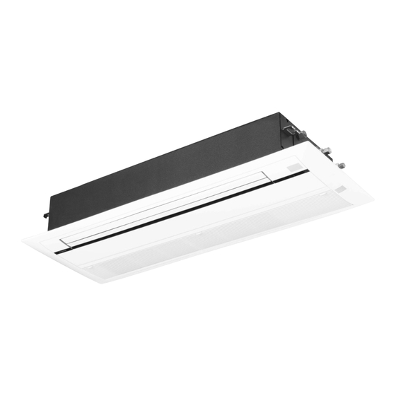
9000/12000/18000 Btu/h
Indoor Unit
Inverter
Ceiling Mounted Cassette
Type (Single Flow)
Table of
Contents
Previous
Page
Next
Page
1
2
3
4
5
Advertisement
Table of Contents
Need help?
Do you have a question about the CCXS09PVM and is the answer not in the manual?
Ask a question
Questions and answers
Related Manuals for Daikin CCXS09PVM
Air Conditioner Daikin CCXS12PVM Service Manual Removal Procedure
Indoor unit 9000/12000/18000 btu/h (31 pages)
Air Conditioner Daikin CCXS18PVM Service Manual Removal Procedure
Indoor unit 9000/12000/18000 btu/h (31 pages)
Air Conditioner Daikin R410A Installation Manual
R410a split series room air conditioner (15 pages)
Air Conditioner Daikin FTKS09JV2S Service Manual
Removal procedure, 2.0/2.2/2.5/2.8/3.5/3.6/4.1/4.2/4.6/ 5.0 kw class, 7000/9000/12000/15000 btu/h class (22 pages)
Air Conditioner Daikin FTXS12LVJU Operation Manual
(42 pages)
Air Conditioner Daikin Air Conditioner Installation Manual
(9 pages)
Air Conditioner Daikin Air Conditioner Installation Manual
(8 pages)
Air Conditioner Daikin Air Conditioner Installation Manual
(17 pages)
Air Conditioner Daikin Air Conditioner Installation Manual
(9 pages)
Air Conditioner Daikin Air Conditioner Installation Manual
Daikin air conditioner (9 pages)
Air Conditioner Daikin Stylish Series Service Manual
Split stylish r32 (76 pages)
Air Conditioner Daikin CTXM15N2V1B Operation Manual
(16 pages)
Air Conditioner Daikin Stylish Series Service Manual
Split r32 (168 pages)
Air Conditioner Daikin CTKM35VVMG Operation Manual
(44 pages)
Air Conditioner Daikin FTXA25C2V1BW Installation Manual
(12 pages)
Air Conditioner Daikin Comfora Operation Manual
(16 pages)
This manual is also suitable for:
Ccxs12pvm
Ccxs18pvm
Table of Contents
Print
Rename the bookmark
Delete bookmark?
Delete from my manuals?
Login
Sign In
OR
Sign in with Facebook
Sign in with Google
Upload manual
Upload from disk
Upload from URL


Need help?
Do you have a question about the CCXS09PVM and is the answer not in the manual?
Questions and answers