
Subscribe to Our Youtube Channel
Related Manuals for HAMPTON BAY VERANDA 499-493


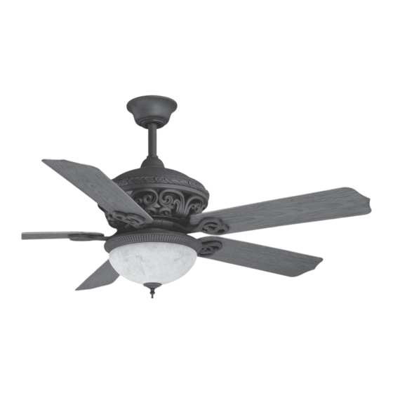
Summary of Contents for HAMPTON BAY VERANDA 499-493
- Page 1 L I F E T I M E W A R R A N T Y ERANDA 499-493...
- Page 2 Hampton Bay Lifetime Limited Warranty The retailer warrants the fan motor to be free from defects in workmanship and material Date Purchased present at time of shipment from the factory for a lifetime after the date of purchase by the original purchaser.
-
Page 3: Table Of Contents
Safety Rules............................. Unpacking Your Fan ......................... Installing Your Fan ........................... Installing the Light Kit........................Operating Your Transmitter ......................Care of Your Fan ..........................Troubleshooting ..........................Specifications ..........................Table of Contents... -
Page 4: Safety Rules
1.To reduce the risk of electric shock, insure electricity has been turned 8. Avoid placing objects in the path of the blades. off at the circuit breaker or fuse box before beginning. To avoid personal injury or damage to the fan and other items, be 2. -
Page 5: Unpacking Your Fan 2
Unpack your fan and check the contents. You should have the following items; Fan blades (5) Light kit 14. Loose parts bag containing: a. Mounting hardware Canopy assembly Glass shades Screws (2 PCs. ) 10. 40 Watt candelabra bulbs (3) Ball/downrod assembly Lock washers (2 PCs.) Coupling cover... -
Page 6: Installing Your Fan
Tools Required Angled ceiling maximum 24 angle P h i l l i p s s c r e w d r i v e r , s t r a i g h t s l o t Provide strong support screwdriver, adjustable wrench, step ladder, and wire cutters. - Page 7 Hanging the Fan Step 7. Align the holes at the bottom of the CUL Listed downrod with the holes in the collar on top of electrical to turn off the power. Follow REMEMBER the motor housing (Fig.7). Carefully insert the the steps below to hang your fan properly: hanger pin through the holes in the collar and downrod.
- Page 8 Step 3. (Fig. 10 & 11) Receiver to house supply Make the Electric Connections wires electrical connections: Connect WARNING: To avoid possible electrical black (hot) wire from the ceiling to the black shock, be sure electricity is turned off at the Code switch wire marked "AC in L"...
- Page 9 INPUT AC120V Outlet box White (neutral) Black (hot) White Green or bare AC SUPPLY Black copper (ground) Black ("AC IN L") White ("AC IN N") Receiver Black ("to motor L") White ("to motor N") Blue ("for light") Ground Ground (Connect to ground wire on (green) Black...
- Page 10 Installing the Wall Transmitter REMEMBER to Shut the Power Off at the Circuit Breaker or Fuse Box. WARNING: HOOK UP IN "SERIES ONLY" DO NOT CONNECT THE HOT AND NEUTRAL WIRES OF ELECTRIC CIRCUIT TO THE TRANSMITTER WALL SWITCH - DAMAGE TO THE SWITCH AND POSSIBLE FIRE COULD OCCUR. Step 1.
- Page 11 Finishing the Installation Installation of Safety Outlet box Support Step 1. Tuck connections neatly into ceiling outlet box. Hanger n additional safety support is provided to bracket Step 2. Slide the canopy up to ceiling and over prevent the fan from falling. Secure the Screws safety cable to the ceiling joist with screw...
- Page 12 Attaching the Fan Blades Motor CAUTION: Remove 5 rubber packing Slot mounts from fan motor assembly and discard before installation. (Fig. 15) Rubber packing mounts Blade arm Step 1 Attach blades to blade arms using three Figure 15 Screws screws and rubber washers. (Fig.
-
Page 13: Installing The Light Kit 10
REMEMBER: To disconnect the power. The Installing the light fan blades must be already attached to the fan. plate Step 1. Remove 1 of the 3 screws from the light plate and keep it for future use. Loosen Step 1. Remove 1 of the 3 screws from the the other 2 screws. -
Page 14: Operating Your Transmitter
Restore power to ceiling fan and test for 4. "OFF-ON "Slide Button: This button turns the power Off and On to proper operation. the Fan and Light(s). 1. " LOW, MED, HI" buttons: Speed settings for warm or cool weather These three buttons are used to set the fan depend on factors such as the room size, speed as follows:... -
Page 15: Care Of Your Fan 12
Here are some suggestions to help you 3. You can apply a light coat of furniture maintain your fan polish to the wood blades for additional protection and enhanced beauty. Cover Touching ceiling 1.Because of the fan's natural movement, small scratches with a light application some connections may become loose. -
Page 16: Troubleshooting
Problem Solution Fan will not start. 1. Check circuit fuses or breakers. 2. Check line wire connections to the fan and switch wire connections in the switch housing. CAUTION: Make sure main power is off. 3. Check to make sure the dip switches from the transmitter and receiver are set to the same frequency. Fan sounds noisy. -
Page 17: Specifications 14
Fan Size Speed Volts Amps Watts N.W. G.W. C.F. Xxxx 52" Medium High These are approximate measures. They do not include Amps and Wattage used by the light kit. Distributed by: Home Depot of Canada Inc. 900-1 Concorde Gate Toronto, Ontario M3C 4H9 Specifications 14.
Need help?
Do you have a question about the VERANDA 499-493 and is the answer not in the manual?
Questions and answers