Mitsubishi Electric MELSEC iQ-R Series Installation Manual
Programmable logic controllers, for digital input and output modules
Hide thumbs
Also See for MELSEC iQ-R Series:
- Programming manual (2110 pages) ,
- User manual (760 pages) ,
- Reference manual (498 pages)
Table of Contents
Advertisement
Available languages
Available languages
Quick Links
MELSEC iQ-R Series
Programmable Logic Controllers
Installation Manual for Digital Input and
Output Modules
Art.no.: 294687 ENG, Version A, 20082015
Safety Precautions
For use by qualified staff only
The instructions in this manual are written for qualified electrical technicians
who are already familiar with automation technology safety standards. System
configuration and layout, installation, setup, servicing and testing of the equip-
ment may only be performed by qualified electrical technicians. Any modifica-
tions to the hardware and/or software of our products not specifically described
in this manual may only be performed by authorised Mitsubishi Electric staff.
Proper product use
The programmable logic controllers (PLCs) of the MELSEC iQ-R series are only
intended for the applications described in this installation manual and/or the
other manuals referenced below. All operating parameters and settings speci-
fied in this manual must be observed. The products described have all been
designed, manufactured, tested and documented in strict compliance with the
relevant safety standards. Unauthorised modification of the hardware or soft-
ware or failure to observe the warnings in this manual and on the products may
result in serious injury to personnel and/or damage to property. Only peripherals
and expansion equipment specifically recommended and approved by Mitsub-
ishi Electric may be used with the programmable logic controllers of the MELSEC
iQ-R series. All and any other uses shall be deemed to be improper.
Safety regulations
All safety and accident prevention regulations relevant to your application
must be observed in your system configuration and layout and for installation,
setup, servicing and testing of these products.
This manual includes warnings to help you use the products properly and
safely. These warnings are identified as follows:
P
DANGER:
User injury hazard.
Failure to observe these safety warnings can result in health
and injury hazards for the user.
E
WARNING:
Equipment damage hazard.
Failure to observe these safety warnings can result in serious
damage to the equipment or other property.
Additional information
You can find more information on these products in the following manuals
● MELSEC iQ-R Series Hardware Manual
● MELSEC iQ-R Series Programming Manual
You can download these manuals from our website free of charge
(https://gb3a.MitsubishiElectric.com/fa/en/).
If you have any questions about installing, programming and operating
MELSEC iQ-R series controllers, please don't hesitate to contact your local sales
office or distributor.
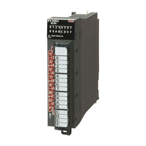
Names and Functions of Parts
Modules with screw terminals
(3)
»
³
(1)
(2)
·
(4)
¿
²
(6)
(7)
¾
(9)
Modules with 40-pin connector(s)
(3)
(3)
» ³
»
³
(1)
(1)
(2)
·
(2)
·
¿
(4)
¿
(4)
´
(5)
(8)
º
(8)
º
¾
¾
(9)
(9)
No.
Description
RUN LED
● ON: In operation
³
● OFF: 5V power off
Indicator LED (For each input/output a red LED is available which
·
indicates the ON/OFF status of I/O (lit when I/O is ON.))
Module identification lamp
»
● Light gray: Input
● Dark orange: Output
Rate indication
¿
Indicates the rated voltage, and input current or output current.
Indication selector switch
● For the input module or output module: A switch for changing
the LED indication to either the first-half 32 points or the latter-
´
half 32 points of a 64-point module
● For the I/O combined module: A switch for changing the LED indi-
cation for input or output
²
Terminal block with 18 screw terminals
Terminal cover
40-pin connector(s)
º
A connector for connecting I/O signal wire from external devices.
Production information marking
¾
Shows the production information (16 digits) of the module.
Pin Arrangement of the Connectors
The connectors are shown in module front view.
40-pin connector
B20
B20
A20
A20
B01
A01
B1
A1
Please note that the 40-pin connector is not a D-sub connector. For connection
the connectors A6CON1, A6CON-2, or A6CON-4 or prefabricated connection
cables can be used (see section Wiring).
Dimensions
The dimensions of all digital I/O modules are identical.
110
110
27.8
131
27.8
131
Unit: mm
Advertisement
Table of Contents

Related Manuals for Mitsubishi Electric MELSEC iQ-R Series


Summary of Contents for Mitsubishi Electric MELSEC iQ-R Series
- Page 1 (see section Wiring). Proper product use Dimensions The programmable logic controllers (PLCs) of the MELSEC iQ-R series are only Modules with 40-pin connector(s) intended for the applications described in this installation manual and/or the The dimensions of all digital I/O modules are identical.
-
Page 2: Specifications
Further general specifications can be found in the Hardware Manual for the 8 V / 6 V / 6 V / Voltage / current for OFF 0.1/0.2/0.4/0.6/1/5/10/20/70 ms, MELSEC iQ-R Series. 2 mA 1 mA 1 mA Max. voltage drop at ON 0.3 V at 0.5 A 0.3 V at 0.5 A... -
Page 3: Installation
Installation Wiring Wiring of the Input Modules Wiring of the Output Modules Modules with screw terminals Modules with screw terminals (RX10, RX40C7) (RY10R2, RY40PT5P) The connection diagram for the digital input modules with removable terminals is The connection diagram for the digital output modules with removable terminals is DANGER DANGER printed on the modules. - Page 4 Vacant Vacant Vacant Vacant 1B03 1A03 2B03 2A03 1B02 COM1 1A02 2B02 COM2 2A02 1B01 COM1 1A01 2B01 COM2 2A01 Mitsubishi Electric Europe B.V. /// FA - European Business Group /// Germany /// Tel.: +49(0)2102-4860 /// Fax: +49(0)2102-4861120 /// https://eu3a.mitsubishielectric.com...
- Page 5 Installationsanleitung angegebenen oder am Produkt angebrachten Warnhin- weise können zu schweren Personen oder Sachschäden führen. Es dürfen nur von MITSUBISHI ELECTRIC empfohlene Zusatz- bzw. Erweiterungsgeräte in Verbindung mit den speicherprogrammierbaren Steuerungen der MELSEC iQ- R-Serie verwendet werden. Jede andere darüber hinausgehende Verwendung oder Benutzung gilt als nicht bestimmungsgemäß.
-
Page 6: Technische Daten
Technische Daten DC-Eingangsmodule (24 V DC) Transistor-Ausgangsmodule Kombinierte Ein-/Ausgangsmodule Technische Daten RX40C7 RX41C4 RX42C4 Technische Daten RY40NT5P RY41NT2P RY42NT2P Technische Daten RH42C4NT2P Allgemeine Betriebsbedingungen Anzahl der Eingänge Anzahl der Ausgänge Anzahl der Eingänge Merkmal Technische Daten Art der Geber Wahlweise plus- oder minusschaltend Ausgangstyp Transistor (minusschaltend) Isolation... - Page 7 Installation Anschluss Anschluss der Eingangsmodule Anschluss der Ausgangsmodule Module mit Schraubklemmen Module mit Schraubklemmen (RX10, RX40C7) (RY10R2, RY40PT5P) Bei den Digital-Eingangsmodulen mit abnehmbarem Klemmenblock ist die Bei den Digital-Ausgangsmodulen mit abnehmbarem Klemmenblock ist die GEFAHR GEFAHR Anschlussbelegung auf das Modul gedruckt. Bitte beachten Sie diese Klem- Anschlussbelegung auf das Modul gedruckt.
- Page 8 1B03 1A03 2B03 2A03 1B02 COM1 1A02 2B02 COM2 2A02 1B01 COM1 1A01 2B01 COM2 2A01 Mitsubishi Electric Europe B.V. /// FA - European Business Group /// Germany /// Tel.: +49(0)2102-4860 /// Fax: +49(0)2102-4861120 /// https://de3a.mitsubishielectric.com...
-
Page 9: Consignes De Sécurité
Sub-D. Les connecteurs A6CON1, A6CON-2 ou A6CON-4 ou des câbles ¾ ment être effectuée par un collaborateur autorisé de Mitsubishi Electric. complètement montées peuvent être utilisées pour le raccordement (voir cha- pitre Raccordement). -
Page 10: Données Techniques
Données techniques Modules d'entrée CC (24 V CC) Modules de sortie à transistor Modules combinés d´entrée/sortie Données techniques RX40C7 RX41C4 RX42C4 Données techniques RY40NT5P RY41NT2P RY42NT2P Données techniques RH42C4NT2P Conditions générales de fonctionnement Nombre d'entrées Nombre de sorties Nombre d'entrées Caractéristique Données techniques Type de capteur... - Page 11 Installation Raccordement Raccordement des modules d'entrée Raccordement des modules de sortie Modules avec bornes à vis Modules avec bornes à vis (RX10, RX40C7) (RY10R2, RY40PT5P) DANGER DANGER L'affectation des broches est inscrite pour les modules d'entrée numérique L'affectation des broches est inscrite pour les modules d'entrée numérique avec répartiteur amovible sur le module.
- Page 12 1B03 1A03 2B03 2A03 1B02 COM1 1A02 2B02 COM2 2A02 1B01 COM1 1A01 2B01 COM2 2A01 Mitsubishi Electric Europe B.V. /// FA - European Business Group /// Germany /// Tel.: +49(0)2102-4860 /// Fax: +49(0)2102-4861120 /// https://eu3a.mitsubishielectric.com...
-
Page 13: Avvertenze Di Sicurezza
MELSEC iQ-R si possono utilizzare solo unità aggiuntive o di espansione consi- Dimensioni gliate da MITSUBISHI ELECTRIC. Ogni altro utilizzo o applicazione che vada oltre quanto illustrato è da considerarsi non conforme. Le dimensioni sono uguali per tutti i moduli. -
Page 14: Specifiche Tecniche
Specifiche tecniche Moduli d'ingresso DC (24 V DC) Moduli di uscita a transistor Moduli combinati ingresso/uscita Specifiche tecniche RX40C7 RX41C4 RX42C4 Specifiche tecniche RY40NT5P RY41NT2P RY42NT2P Specifiche tecniche RH42C4NT2P Condizioni di funzionamento generali Numero degli ingressi Numero di uscite Numero degli ingressi Caratteristica Specifiche tecniche Tipo di sensori... -
Page 15: Installazione
Installazione Collegamento Collegamento dei moduli d'ingresso Collegamento dei moduli d'uscita Moduli con morsetti a vite Moduli con morsetti a vite (RX10, RX40C7) (RY10R2, RY40PT5P) PERICOLO Gli schemi di connessione per i moduli d'ingresso digitali con morsettiera Gli schemi di connessione per i moduli d'ingresso digitali con morsettiera estraibile sono stampati direttamente sul modulo. - Page 16 1B03 1A03 2B03 2A03 pato pato pato pato 1B02 COM1 1A02 2B02 COM2 2A02 1B01 COM1 1A01 2B01 COM2 2A01 Mitsubishi Electric Europe B.V. /// FA - European Business Group /// Germany /// Tel.: +49(0)2102-4860 /// Fax: +49(0)2102-4861120 /// https://eu3a.mitsubishielectric.com...
- Page 17 MELSEC sólo se permite el empleo de los dispositivos adicionales o de ampliación recomenda- dos por MITSUBISHI ELECTRIC. Todo empleo o aplicación distinto o más amplio del indicado se considerará como no reglamentario.
- Page 18 Datos técnicos Módulos de entrada AC (24 V DC) Módulos de salida de transistor Módulos de entrada y salida combinados Datos técnicos RX40C7 RX41C4 RX42C4 Datos técnicos RY40NT5P RY41NT2P RY42NT2P Datos técnicos RH42C4NT2P Condiciones generales de operación Número de entradas Número de salidas Número de salidas Característica...
-
Page 19: Instalación
Instalación Conexión Conexión de los módulos de entrada Conexión de los módulos de salida Módulos con bornes de tornillo Módulos con bornes de tornillo (RX10, RX40C7) (RY10R2, RY40PT5P) En los módulos de entrada digitales con bloque de bornes desmontable, el En los módulos de salida digitales con bloque de bornes desmontable, el dia- diagrama de conexiones está... - Page 20 1B03 1A03 2B03 2A03 1B02 COM1 1A02 2B02 COM2 2A02 1B01 COM1 1A01 2B01 COM2 2A01 Mitsubishi Electric Europe B.V. /// FA - European Business Group /// Germany /// Tel.: +49(0)2102-4860 /// Fax: +49(0)2102-4861120 /// https://eu3a.mitsubishielectric.com...
- Page 21 рять аппаратуру разрешается только квалифицированным специалистам. ¾ Любое внесение изменений в аппаратуру и программное обеспечение данной продукции, если они не предусмотрены в этом руководстве, допу- скается только с разрешения специалистов фирмы Mitsubishi Electric. Модули с 40-контактными разъёмами Использование по назначению » ³...
-
Page 22: Технические Данные
Технические данные Модули входа пост. тока (24 V DC) Модули транзисторных выходов Композитные модули ввода/вывода Технические данные RX40C7 RX41C4 RX42C4 Технические данные RY40NT5P RY41NT2P RY42NT2P Технические данные RH42C4NT2P Общие условия эксплуатации Кол-во входов Кол-во выходов Кол-во входов Параметр Технические данные Тип... - Page 23 Монтаж Электропроводка Подключение модулей входа Подключение модулей выхода Модули с клеммной колодкой Модули с клеммной колодкой (RX10, RX40C7) (RY10R2, RY40PT5P) ОПАСНОСТЬ ОПАСНОСТЬ Схема подключения модулей дискретного входа со съёмными клемм- Схема подключения модулей дискретного выхода со съёмными клеммны- ными колодками напечатана на модулях. Руководствуйтесь данными схе- ми...
- Page 24 1B03 1A03 2B03 2A03 ется ется ется ется 1B02 COM1 1A02 2B02 COM2 2A02 1B01 COM1 1A01 2B01 COM2 2A01 Mitsubishi Electric Europe B.V. /// FA - European Business Group /// Germany /// Tel.: +49(0)2102-4860 /// Fax: +49(0)2102-4861120 /// https://eu3a.mitsubishielectric.com...
- Page 25 Tylko urządzenia peryferyjne i sprzęt rozszerzający, wyraźnie zalecane i dopuszczone przez Mitsubishi Electric, mogą być używane przez programowalne sterowniki logiczne z serii MELSEC iQ-R. Wszystkie inne zastosowania będą uważane za niewłaściwe.
- Page 26 Wymagania Moduły z wejściami DC (24 V DC) Moduły z wyjściami tranzystorowymi Mieszane moduły wejściowo/wyjściowe Wymagania RX40C7 RX41C4 RX42C4 Wymagania RY40NT5P RY41NT2P RY42NT2P Wymagania RH42C4NT2P Ogólne wymagania Liczba wejść Liczba wyjść Liczba wejść Pozycja Wymagania Rodzaj czujników Wspólny zacisk dodatni/ujemny Rodzaj wyjścia Tranzystor (sink) Metoda izolacji...
- Page 27 Instalacja Okablowanie Okablowanie modułów wejściowych Okablowaniemodułów wyjściowych Moduły z zaciskami śrubowymi Moduły z zaciskami śrubowymi (RX10, RX40C7) (RY10R2, RY40PT5P) NIEBEZPIECZEŃSTWO NIEBEZPIECZEŃSTWO Schemat połączeń cyfrowych modułów wejściowych z wymiennymi listwami Schemat połączeń cyfrowych modułów wejściowych z wymiennymi listwami zaciskowymi, wydrukowany jest na modułach. Przy kablowaniu modułów zaciskowymi, wydrukowany jest na modułach.
- Page 28 1B03 1A03 2B03 2A03 1B02 COM1 1A02 2B02 COM2 2A02 1B01 COM1 1A01 2B01 COM2 2A01 Mitsubishi Electric Europe B.V. /// FA - European Business Group /// Germany /// Tel.: +49(0)2102-4860 /// Fax: +49(0)2102-4861120 /// https://eu3a.mitsubishielectric.com...
-
Page 29: Biztonsági Óvintézkedések
útmutatóban leírtak be nem tartása súlyos személyi sérülést, illetve anyagi károkat okozhat. A MELSEC iQ-R sorozat PLC egységeihez kizárólag a Mitsubishi Electric által javasolt és jóváhagyott kiegészítők és bővítmények használhatók. Minden más használat és alkalmazás nem rendeltetésszerűnek minősül. -
Page 30: Műszaki Adatok
Műszaki adatok DC bemeneti modulok (24 V DC) Tranzisztoros kimeneti modulok Kombinált I/O modulok Műszaki adatok RX40C7 RX41C4 RX42C4 Műszaki adatok RY40NT5P RY41NT2P RY42NT2P Műszaki adatok RH42C4NT2P Általános üzemeltetési feltételek Bemenetek száma Kimenetek száma Bemenetek száma Feltétel Műszaki adatok Jeladó típusa Választható... - Page 31 Felszerelés Csatlakozás A bemeneti modulok csatlakoztatása A kimeneti modulok csatlakoztatása Kapocsléccel ellátott modulok Modulok csatlakozókapcsokkal (RX10, RX40C7) (RY10R2, RY40PT5P) A levehető kapocsléccel rendelkező digitális bemeneti modulok esetén a kap- A levehető kapocsléccel rendelkező digitális kimeneti modulok esetén a kap- VESZÉLY VESZÉLY csolási rajz a modulra van nyomtatva.
- Page 32 Szabad Szabad Szabad Szabad 1B03 1A03 2B03 2A03 1B02 COM1 1A02 2B02 COM2 2A02 1B01 COM1 1A01 2B01 COM2 2A01 Mitsubishi Electric Europe B.V. /// FA - European Business Group /// Germany /// Tel.: +49(0)2102-4860 /// Fax: +49(0)2102-4861120 /// https://eu3a.mitsubishielectric.com...
-
Page 33: Obslužné Prvky
´ ku. Smějí se používat pouze příslušenství a periférie specificky schválené spo- lečností MITSUBISHI ELECTRIC. Jakékoli jiné aplikace produktu budou považo- vány za nesprávné. Příslušné bezpečnostní předpisy Během návrhu systému, instalace, nastavení, údržby, servisu a zkoušení těchto produktů... -
Page 34: Technické Údaje
Technické údaje Vstupní moduly DC (stejnosměrné, 24 Vss) Tranzistorové výstupní moduly Kombinované vstupní/výstupní moduly Technické údaje RX40C7 RX41C4 RX42C4 Technické údaje RY40NT5P RY41NT2P RY42NT2P Technické údaje RH42C4NT2P Všeobecné provozní podmínky Počet vstupů Počet výstupů Počet vstupů Parametr Technické údaje Druh spínání Spínající... - Page 35 Instalace Připojení Připojení vstupních modulů Připojení výstupních modulů Modul se šroubovými svorkami Modul se šroubovými svorkami (RX10, RX40C7) (RY10R2, RY40PT5P) U digitálních vstupních modulů s odnímatelným svorkovnicovým blokem je zapo- U digitálních výstupních modulů s odnímatelným svorkovnicovým blokem je zapo- NEBEZPEČÍ...
- Page 36 žit žit žit žit 1B03 1A03 2B03 2A03 1B02 COM1 1A02 2B02 COM2 2A02 1B01 COM1 1A01 2B01 COM2 2A01 Mitsubishi Electric Europe B.V. /// FA - European Business Group /// Germany /// Tel.: +49(0)2102-4860 /// Fax: +49(0)2102-4861120 /// https://eu3a.mitsubishielectric.com...
-
Page 37: Güvenlik Önlemleri
MELSEC iQ-R ailesi prog- ´ ramlanabilir lojik kontrolörler ile ilintili olarak sadece Mitsubishi Electric tarafından önerilen ve onaylanan ek cihazlar ve genişletme cihazları kullanıla- bilir. Bunun dışındaki her türlü kullanım, amacına uygun olmayan kullanım ola- rak kabul edilir. - Page 38 Özellikler DC Giriş Modülleri (24 V DC) Transistör Çıkış Modülleri Kompozit Giriş/Çıkış Modülleri Özellikler RX40C7 RX41C4 RX42C4 Özellikler RY40NT5P RY41NT2P RY42NT2P Özellikler RH42C4NT2P Genel özellikler Giriş sayısı Çıkış sayısı Giriş sayısı Madde Özellikler Sensör tipi Pozitif/Negatif ortak Çıkış tipi Transistör (negatif ) Yalıtım yöntemi Optokuplör çalışma sırasında...
- Page 39 Montaj Kablolama Giriş Modülleri Kablolaması Çıkış Modülleri Kablolaması Vidalı terminallere sahip modüller Vidalı terminallere sahip modüller (RX10, RX40C7) (RY10R2, RY40PT5P) TEHLİKE TEHLİKE Çıkarılabilir terminallere sahip dijital giriş modülleri için bağlantı şeması Çıkarılabilir terminallere sahip dijital çıkış modülleri için bağlantı şeması modüllerin içine basılmış...
- Page 40 Boşta Boşta Boşta Boşta 1B03 1A03 2B03 2A03 1B02 COM1 1A02 2B02 COM2 2A02 1B01 COM1 1A01 2B01 COM2 2A01 Mitsubishi Electric Europe B.V. /// FA - European Business Group /// Germany /// Tel.: +49(0)2102-4860 /// Fax: +49(0)2102-4861120 /// https://eu3a.mitsubishielectric.com...
Need help?
Do you have a question about the MELSEC iQ-R Series and is the answer not in the manual?
Questions and answers