
Subscribe to Our Youtube Channel
Related Manuals for Planet Networking & Communication GS-4210 Series


Summary of Contents for Planet Networking & Communication GS-4210 Series
- Page 1 8-/16-/24-/48-Port 10/100/1000T + 2-/4-Port 100/1000X SFP Managed Switch GS-4210 Series Quick Installation Guide...
-
Page 2: Table Of Contents
Table of Contents 1. Package Contents ..................3 2. Requirements ..................... 5 3. Terminal Setup ................... 6 3.1 Logging on to the Console..............7 3.2 Configuring IP Address via the Console ..........7 3.3 Storing Current Switch Configuration ............. 9 4. Starting Web Management .................10 4.1 Logging in to the Managed Switch ............10 4.2 Saving Configuration via the Web ............13 5. Recovering Back to Default Configuration .............14 6. -
Page 3: Package Contents
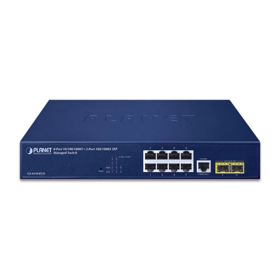
1. Package Contents Thank you for purchasing PLANET GS-4210 Managed Switch series. The descriptions of this series are shown below: Model Description 8-Port 10/100/1000T + 2-Port 100/1000X SFP Managed GS-4210-8T2S Switch 8-Port 10/100/1000T 802.3at PoE + 2-Port 100/1000X SFP GS-4210-8P2S Managed Switch 8-Port 10/100/1000T 802.3at PoE + 2-Port 10/100/1000T GS-4210-8P2C +2-Port 100/1000X SFP Managed Switch 16-Port Layer 2 Managed Gigabit Ethernet Switch w/2 SFP GS-4210-16T2S Interfaces 16-Port 10/100/1000T 802.3at PoE + 2-Port 100/1000X GS-4210-16P2S SFP Managed Switch 24-Port Layer 2 Managed Gigabit Ethernet Switch w/2 SFP GS-4210-24T2S Interfaces 24-Port 10/100/1000T 802.3at PoE + 2-Port 100/1000X GS-4210-24P2S SFP Managed Switch 24-Port 10/100/1000T + 4-Port 100/1000X SFP Managed GS-4210-24T4S Gigabit Switch 24-Port 10/100/1000T + 4-Port 100/1000X SFP Managed GS-4210-24T4SR Gigabit Switch with 36-72V DC Redundant Power... - Page 4 Open the box of the Managed Switch and carefully unpack it. The box should contain the following items: z The Managed Switch x 1 z Quick Installation Guide x 1 z RS232 to RJ45 Cable x 1 z Rubber Feet x 4 z Two Rack-mounting Brackets with Attachment Screws x 1 z Power Cord x 1 z SFP Dust-proof Cap SFP Dust-proof Caps GS-4210-8P2C GS-4210-8T2S GS-4210-8P2S GS-4210-16T2S GS-4210-16P2S GS-4210-24T2S GS-4210-24P2S GS-4210-24T4S...
-
Page 5: Requirements
2. Requirements z Workstations running Windows XP/2003/2008/2012/Vista/7/8/10, MAC OS X or later, Linux, UNIX, or other platforms are compatible with TCP/IP protocols. z Workstations are installed with Ethernet NIC (Network Interface Card). z Serial Port Connection (Terminal) The above Workstations come with COM Port (DB9) or USB-to-RS-232 converter. The above Workstations have been installed with terminal emulator, such as Tera Term, PuTTY or Hyper Terminal included in Windows XP/2003. Serial cable -- one end is attached to the RS-232 serial port, while the other end to the console port of the Managed Switch. -
Page 6: Terminal Setup
3. Terminal Setup To configure the system, connect a serial cable to a COM port on a PC or notebook computer while the other end to RJ45 console port of the Managed Switch. Managed Switch Console Serial Port 115200,N,8,1 115200,N,8,1 PC / Workstation with Terminal Emulation Software RJ45 to RS232 Cable... -
Page 7: Logging On To The Console
3.1 Logging on to the Console Once the terminal is connected to the device, power on the Managed Switch and the terminal will run self testing procedures. Then, the following message asks to log in user name and password. The factory default user name and password are shown as follows and the login screen in Figure 3-3 appears. - Page 8 To check the current IP address or modify a new IP address for the Managed Switch, please use the procedures as follows: Display of the current IP address 1. On “GS-4210-24T4S#” prompt, enter “show ip”. 2. The screen displays the current IP address, subnet mask and gateway shown in Figure 3-4. Figure 3-4: IP Information Screen Configuration of the IP address 3.
-
Page 9: Storing Current Switch Configuration
5. Repeat Step 1 to check if the IP address has changed. If the IP is successfully configured, the Managed Switch will apply the new IP address setting immediately. You can access the Web interface of Managed Switch through the new I s.P addres. If you are not familiar with console command or the related param- eter, enter “?” aanytime in console to get the help description. Note 3.3 Storing Current Switch Configuration In switches, the running configuration file is stored in the RAM. In the current version, the running configuration sequence can be saved from the RAM to FLASH by saving command or copying running-config startup-config command, so that the running configuration sequence becomes the startup configuration file,... -
Page 10: Starting Web Management
4. Starting Web Management The following shows how to start up the Web Management of the Managed Switch. Note the Managed Switch is configured through an Ethernet connection. Please make sure the manager PC must be set to the same IP subnet address. For example, the default IP address of the Managed Switch is 192.168.0.100;... - Page 11 Figure 4-2: Web Login Screen 1. The following web screen based on the GS-4210-24T4S is the same as those of other GS-4210 series. 2. The PoE function is only available for GS-4210-8P2C, GS-4210- Note 8P2S, GS-4210-16P2S and GS-4210-24P2S. 3. After entering the password, the main screen appears as Figure 4-3 shows. Figure 4-3: Web Main Screen of Managed Switch...
- Page 12 The Switch Menu on the left of the Web page lets you access all the commands and statistics the Managed Switch provides. Figure 4-4: Switch Menu Now, you can use the Web management interface to continue the switch management. Please refer to the user’s manual for more.
-
Page 13: Saving Configuration Via The Web
4.2 Saving Configuration via the Web Save all applied changes and set the current configuration as a startup configuration. The startup-configuration file will be loaded automatically across a system reboot. 1. Click “SAVE > Save Configurations to FLASH” to log in “Configuration Manager” Page. 2. -
Page 14: Recovering Back To Default Configuration
5. Recovering Back to Default Configuration IP address has been changed or admin password has been forgotten – To reset the IP address to the default IP address “192.168.0.100” or reset the login password to default value, press the reset button on the front panel for about 10 seconds. After the device is rebooted, you can log in the Web interface management within the same subnet of 192.168.0.xx. - Page 15 + 2-Port 100/1000X SFP Managed Switch 16-Port 10/100/1000T 802.3at PoE GS-4210-16P2S 1000 1000 10/100 RESET PoE-in-Use Reset Figure 5-5: GS-4210-16P2S Reset Button 24-Port 10/100/1000T + 2-Port 100/1000X SFP Managed Switch 1000 Reset 1000 GS-4210-24T2S 10/100 Reset Figure 5-6: GS-4210-24T2S Reset Button + 2-Port 100/1000X SFP Managed Switch 24-Port 10/100/1000T 802.3at PoE...
-
Page 16: Customer Support
6. Customer Support Thank you for purchasing PLANET products. You can browse our online FAQ resource and User’s Manual on PLANET Web site first to check if it could solve your issue. If you need more support information, please contact PLANET switch support team. PLANET online FAQs: http://www.planet.com.tw/en/support/faq Switch support team mail address: support@planet.com.tw GS-4210 Series User’s Manual: https://www.planet.com.tw/en/support/downloads?&method=keyword&keyword= GS-4210&view=3#list Copyright © PLANET Technology Corp. 2021. Contents are subject to revision without prior notice. PLANET is a registered trademark of PLANET Technology Corp. All other trademarks belong to their respective owners.
Need help?
Do you have a question about the GS-4210 Series and is the answer not in the manual?
Questions and answers