Table of Contents
Advertisement
Table of Contents
Introduction...............................................................................................................1
Main Functions..........................................................................................................1
Specifications............................................................................................................2
Programming............................................................................................................3
1. Button Definition............................................................................................3
2. Setting Methods..............................................................................................3
3. Inquiry Function..............................................................................................3
4. System Initialization.........................................................................................4
5. Menu Diagram at Different Regeneration Modes...................................................5
6. Default Settings..............................................................................................7
Manual Regeneration.................................................................................................7
Water Hardness Adjustment (Optional for Softener Valve)..................................................7
Optional Parts...........................................................................................................8
1. Inlet/Outlet Screw Standards................................................................................8
2. Inlet/Outlet Screw Adaptor (Optional).....................................................................8
3. Inlet/Outlet Connections Types..............................................................................9
4. Drain Line Flow Controls (DLFC) and Injector.........................................................10
5. Bypass Assembly..............................................................................................11
Valve Powerhead Assembly......................................................................................12
Valve Body Assembly................................................................................................14
Bypass Assembly.....................................................................................................17
General Valve Installation...........................................................................................19
Trouble Shooting......................................................................................................20
Advertisement
Table of Contents

Related Manuals for Canature BNT95 Series

Summary of Contents for Canature BNT95 Series
-
Page 1: Table Of Contents
Table of Contents Introduction………………………………………………………………………………………………...1 Main Functions…………………………………………………………………………………………….1 Specifications……………………………………………………………...………………………………2 Programming………………………………………………………………………………………………3 1. Button Definition…………………………………...…………………………………………..3 2. Setting Methods………………………………………………………………………………….3 3. Inquiry Function………………………………………………………………………………….3 4. System Initialization……………………………………………………………………………..4 5. Menu Diagram at Different Regeneration Modes……………………………………………5 6. Default Settings………………………………………………………………………………….7 Manual Regeneration…………………………………………………………………………………….7 Water Hardness Adjustment (Optional for Softener Valve)……………………………………..……7 Optional Parts……………………………………………………………………………………………..8 1. -
Page 2: Introduction
BNT95 Series Valve Operation Manual Introduction This valve is controlled with simple, user-friendly electronics displayed on a large LCD screen. The main page displays the current time, last regeneration date and regeneration mode. In addition, the main page also shows key valve information including: volume remaining, flow rate (meter mode);... -
Page 3: Specifications
BNT95 Series Valve Operation Manual Metric format and US format are available to meet the different customers’ requirements. ● Multi-Language Function: Chinese, English and Spanish are available to meet the different country. ● Smart Controller: Regeneration Capacity,Regeneration Days and Refill Time can be calculated. -
Page 4: Programming
BNT95 Series Valve Operation Manual Programming 1.Button Definition: “MENU”button: ● Enter or exit the system menu. ● Press and hold the button for 3 seconds to unlock the screen. “SET/REGEN.”button: ● Press this button to select a program or to save the settings. -
Page 5: 4.System Initialization
BNT95 Series Valve Operation Manual Calendar Clock Mode Meter Mode (Meter Immediate, Meter Delay, Meter Override) Screen shows Current Time, Last Regeneration day, Regeneration Mode, the Remaining Days of next regeneration, the Capacity Remaining of next regeneration and current Flow Rate. -
Page 6: Manual Regeneration
BNT95 Series Valve Operation Manual Any button will be overridden at this time. When the valve reaches the service position, it will return to standby display. 5.Manual Regeneration: Press and hold the “SET/REGEN.” button for 3 seconds to initiate a manual regeneration, and screen will display: When the valve reaches “Backwash”... - Page 7 BNT95 Series Valve Operation Manual When the valve reaches “Brine” position, screen will display: When Brine Remaining time reaches zero or any button is operated, valve will be advanced to the rest of cycle position: Rinse and Refill, just like the above cycles.
- Page 8 BNT95 Series Valve Operation Manual Press the“MENU”button to “Time” setting item. You can only change the flashing parameters. ·Region setting Unit format can be selected in “Region” setting item. Setting method: Press the “ /+” or “ /-” button to move the cursor to the desired parameter.
- Page 9 BNT95 Series Valve Operation Manual ·Holiday Mode setting Holiday Mode can be selected in “Holiday Mode” setting item. You should input the end of date of holiday to let the valve clean the media during your holiday. Once you turn on the “Holiday Mode”, the valve’s regeneration only has two cycles: Backwash and Rinse.
- Page 10 BNT95 Series Valve Operation Manual Automatic Calculate mode and Manual Settings mode can be selected in the “Advanced Settings” item. The key regeneration parameters (Capacity, Refill Time, etc.) can be calculated in the “Automatic Calculate” mode. Automatic Calculate mode’s page under different regeneration mode is as follows:...
- Page 11 BNT95 Series Valve Operation Manual Calendar Clock Meter Immediate Meter Delayed Meter Override ‥Regen. Mode Four Regeneration modes can be selected to meet different installation environment. Calendar Clock: the unit will initiate regeneration at the next pre-set regeneration time based on the interval of days between regeneration days.
- Page 12 BNT95 Series Valve Operation Manual setting and initiate regeneration. ‥Regen. Time This setting controls the time of day when regeneration will start. ‥Regen. Days This value is the interval (days) between regenerations. It is used to determine how many days between regenerations ‥Water Usage...
- Page 13 BNT95 Series Valve Operation Manual ‥Water Capacity This value is the total capacity between regenerations. It is used to determine how many gallons can be used between regenerations ‥Data Entry This setting is used to calculate the key regeneration parameters (Capacity, Refill Time, etc.).
- Page 14 BNT95 Series Valve Operation Manual Refill time is calculated under Automatic Calculate mode ‥Restore Defaults This setting allows the current settings to be erased and changed back to the default settings. ·System Information Press the “ /+” or “ /-” button to inquire some information of valve by entering “System Information”...
- Page 15 BNT95 Series Valve Operation Manual In “Total Regenerations” and “Peak Flow Rate” page, press and hold “SET/REGEN.” button for 3 seconds can reset the value to zero. - 14 -...
- Page 16 BNT95 Series Valve Operation Manual Removing Controller Assembly Manually removing the Controller Assembly: • Press and hold Manual Button • With 8 hex key, insert Cam Hole, turn the Cam anti-clockwise to the marked position • Remove the Connector • Remove the Locking Bar •...
- Page 17 BNT95 Series Valve Operation Manual Replacing Drain Line Flow Control and Brine Line Flow Control To replace the Drain Line Flow Control (DLFC): • Remove the Clip • Pull the Drainlet outward • Pull the DLFC Holder outward from the Drainlet •...
- Page 18 BNT95 Series Valve Operation Manual Replacing Injectors To replace the Injectors: • Remove the Connector • Remove the Screw • Slightly pull the Injector Body and Injector Cover outward • Slightly pull out the Screen • Replace the Nozzle • Slightly pull out the Air Disperser •...
-
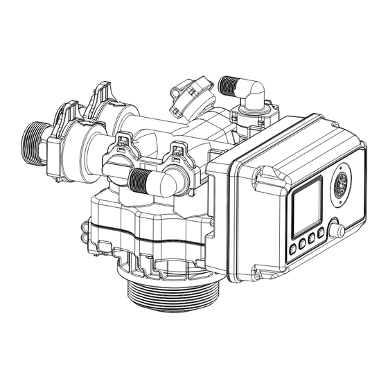
Page 19: Valve Powerhead Assembly
BNT95 Series Valve Operation Manual Valve Powerhead Assembly Bnt95 Powerhead Assembly Parts List Item No. Part No. Part Description Quantity 05040038 Bnt95 Cable Jaket(without hole) 26010028 O-Ring-Ø28×2.65 05040086 O-Ring-Ø8×2 05040005 Bnt95 Housing 05040008 Bnt95 Driving Cam 05040032 O-Ring-Ø4×1.5 05040009 Bnt95 Driven Cam 05010078 Magnet-Ø4x3... - Page 20 BNT95 Series Valve Operation Manual 05040044 Bnt95 Motor Pin 05040047 Bnt95 Motor (AC12V,2RPM) 05040046 Bnt95 Gear Spring 05040040 Bnt95 Gear 05040033 Bnt95 Piston Rod Bush 05040041 Bnt95 Manual Button 05040085 O-Ring-Ø10×2.5 05040051 Bnt95 Main PCB 05056529 Bnt465 Button 05040043 Bnt95 Housing Seal...
-
Page 21: Valve Body Assembly
BNT95 Series Valve Operation Manual Valve Body Assembly Bnt95 Valve Body Assembly Parts List Item No. Part No. Part Description Quantity 05040025 Bnt95 Piston Rod 05040033 Bnt95 Piston Rod Bush 05040029 Bnt95 Quad Ring Holder 05040004 Bnt95 End Plug Retainer... - Page 22 BNT95 Series Valve Operation Manual 05040012 Bnt95 Drainlet 05056129 O-Ring-Ø23×3 05040015 Bnt95 Plug 05040018 Bnt95 Clip (S) 05040017 Bnt95 Clip (L) 05040034 Bnt95 Impeller Bush 05040020 Bnt95 Impeller Holder 05040014 Bnt95 Adaptor 05040019 Bnt95 Impeller 05010078 Magnet-Ø4x3 05040045 Bnt95 Impeller Pin 26010030 O-Ring-Ø48.7×3.55...
- Page 23 BNT95 Series Valve Operation Manual 05040066 Bnt95 Throat-6 05040068 Bnt95 Throat-7 05040035 Bnt95 Air Disperser 07060007 Valve Bottom Connector 05056063 O-Ring-Ø78.74×5.33 26010103 O-Ring-Ø25×3.55 05040001 Bnt95 Valveset (2.5inch) O-Ring-Ø108×5.3 05040091 Bnt95 Seal Holder 05040088 Screw-M6×30 (Hexagon with Washer) 05040090 Bnt95 Valveset (4inch) 05040082 O-Ring-Ø47×3...
- Page 24 BNT95 Series Valve Operation Manual Meter Flow Data 90.00 80.00 70.00 60.00 50.00 40.00 30.00 20.00 10.00 0.00 0.00 10.00 20.00 30.00 40.00 50.00 60.00 Service Flow Rate (GPM) 90.0 80.0 70.0 60.0 50.0 40.0 30.0 20.0 10.0 0.00 10.00 20.00...
- Page 25 BNT95 Series Valve Operation Manual Injector Flow Data 125.00 125.00 100.00 100.00 75.00 75.00 50.00 50.00 25.00 25.00 0.00 0.00 0.00 0.50 1.00 1.50 2.00 2.50 3.00 3.50 0.00 0.50 1.00 1.50 2.00 2.50 3.00 3.50 Brine Flow Rate(GPM) Brine Flow Rate(GPM)...
- Page 26 BNT95 Series Valve Operation Manual Drain Line Flow Control Data (DLFC) 140.00 140.00 120.00 120.00 100.00 100.00 80.00 80.00 60.00 60.00 40.00 40.00 20.00 20.00 0.00 0.00 0.00 10.00 20.00 30.00 40.00 0.00 10.00 20.00 30.00 40.00 Backwash Flow Rate (GPM)
- Page 27 BNT95 Series Valve Operation Manual Brain Line Flow Control Data (BLFC) 140.00 140.00 120.00 120.00 100.00 100.00 80.00 80.00 60.00 60.00 40.00 40.00 20.00 20.00 0.00 0.00 0.00 2.00 4.00 6.00 8.00 10.00 0.00 2.00 4.00 6.00 8.00 10.00 Backwash Flow Rate (GPM)
-
Page 28: General Valve Installation
BNT95 Series Valve Operation Manual General Valve Installation Water Pressure Minimum 25 PSI Electrical Supply Uninterrupted AC Existing Plumbing Free of any deposits or built-ups inside pipes Locate close to drain and connect according to Softener Location plumbing codes Always provide for bypass valve if unit is not... -
Page 29: Trouble Shooting
BNT95 Series Valve Operation Manual Trouble Shooting Issue Possible Cause Possible Solution A. Unit fails to initiate a 1. No power supply. Check electrical service, fuse, etc. regeneration cycle. 2. Power failure Reset time of day. 1. By-pass valve open.
Need help?
Do you have a question about the BNT95 Series and is the answer not in the manual?
Questions and answers