
Related Manuals for Aqualisa Quartz Digital QZD.B3.DS.14


Summary of Contents for Aqualisa Quartz Digital QZD.B3.DS.14
- Page 1 Quartz Digital Remote controls Installation guide Quartz Digital remote control installation instructions Page 1...
- Page 2 Quartz Digital remotes Quartz Digital remote control Quartz Digital wireless remote QZD.B3.DS.14 QZD.B3.WR.14 Quartz Digital Divert remotes Quartz Digital Divert wireless remote Quartz Digital Divert remote control QZD.B3.DVWR.14 QZD.B3.DVDS.14 Quartz Digital remote control installation instructions Page 2...
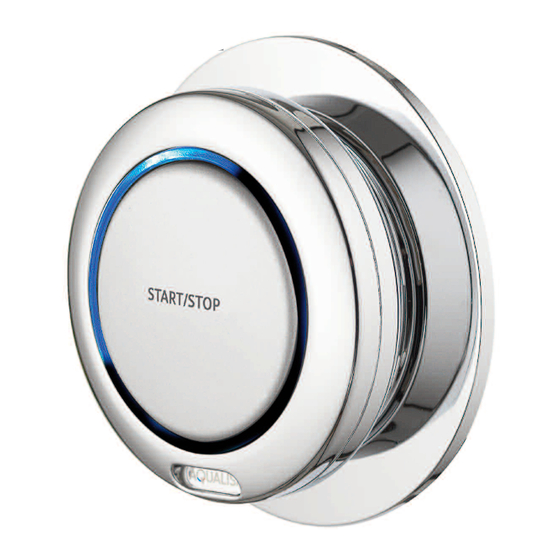
- Page 3 Components - Quartz Digital remote control Literature not shown Components - Quartz Digital wireless remote Literature not shown Quartz Digital remote control installation instructions Page 3...
- Page 4 DIVERT OR NON-DIVERT SHOWER SYSTEMS. DIVERT REMOTES ARE NOT COMPATIBLE WITH NON-DIVERT SYSTEMS AND VICE VERSA. The Quartz Digital remote controls are not suitable for use with any other Aqualisa Digital product range. THIS PRODUCT MUST BE INSTALLED BY A COMPETENT PERSON IN ACCORDANCE WITH ALL RELEVANT CURRENT WATER AND ELECTRICAL SUPPLY REGULATIONS.
- Page 5 Installation instructions Quartz Digital remote control In addition to the guide below it is essential that the written instructions below are read and understood and that you have all the necessary components (shown below) before commencing installation. Failure to install the product in accordance with these instructions may adversely affect the warranty terms and conditions.
- Page 6 10m Data 10m Data Cable Cable 2m Data Cable Wiring diagram - Quartz Digital Divert Using the back plate as a template, mark the position of the fixing screws and a Ø20mm hole for the data cable rear entry point. Prepare suitable wall fixings to accommodate no.
- Page 7 Prepare a suitable route and install the 10m low voltage data cable leaving a working end of at least 70mm including the connector plug. The end of the data cable closest to the processor should terminate at a maximum of 500mm from the processor to allow for connection to the data cable connection block.
- Page 8 Locate the button assembly onto the back plate assembly with the ‘Start/stop’ or ‘Start/stop/divert’ graphic in the diagonal position. Rotate the button clockwise so the ‘Start/stop’ or ‘Start/stop/divert’ graphic is in the horizontal position to lock the button in place. To release the button, insert a small flat bladed screw driver into the small opening at the 7 o’clock position, to release the...
- Page 9 Prior to commissioning the Quartz Digital remote control button following the procedure below, please refer to the installation instructions provided with the main Quartz Digital product to complete the installation of the Digital processor. Quartz Digital wireless remote In addition to the guide below it is essential that the written instructions below are read and understood and that you have all the necessary components (shown below) before commencing installation.
- Page 10 10m Data Cable 1m Data Cable 2m Data Cable Wiring diagram - Quartz Digital Divert Using the back plate as a template, mark the position of the fixing screws. Quartz Digital remote control installation instructions Page 10...
- Page 11 Drill and prepare the fixing points using the fixings supplied, if suitable. Fit the wall plate onto the back plate taking care to line up the location slots on the back plate, and then fit the assembly onto the wall. Using a large flat bladed screwdriver, carefully undo the battery cover by turning it a quarter turn.
- Page 12 Locate the button assembly onto the back plate assembly with the ‘Start/stop’ or ‘Start/stop/divert’ graphic in the horizontal position. Insert the top edge first then carefully click the bottom into position. If required, to release the button, insert a small flat bladed screwdriver into the small opening at the 6 o’clock position, to release the locking mechanism and then pull the bottom of the button forwards.
- Page 13 Insert the other end of the patch lead data cable into the receiver box. Secure the receiver box to a flat horizontal surface using suitable fixings. If required, the top of the receiver box can be removed by first removing the fixing screws securing the receiver box to the flat surface.
- Page 14 Part No.700998 Issue 01 Jan 14 Please note that calls may be recorded for training and quality purposes The company reserves the right to alter, change or modify the product specifications without prior warning ® Registered Trademark Aqualisa Products Limited...
Need help?
Do you have a question about the Quartz Digital QZD.B3.DS.14 and is the answer not in the manual?
Questions and answers