Sign In
Upload
Download
Table of Contents
Contents
Add to my manuals
Delete from my manuals
Share
URL of this page:
HTML Link:
Bookmark this page
Add
Manual will be automatically added to "My Manuals"
Print this page
×
Bookmark added
×
Added to my manuals
Manuals
Brands
Hioki Manuals
Test Equipment
FT3405
Instruction manual
Hioki FT3405 Instruction Manual
Hide thumbs
1
2
Table Of Contents
3
4
5
6
7
8
9
10
11
12
13
14
15
16
17
18
19
20
21
22
23
24
25
26
27
28
29
30
31
32
33
34
35
36
37
38
39
40
41
42
43
44
45
46
47
48
49
50
page
of
50
Go
/
50
Contents
Table of Contents
Troubleshooting
Bookmarks
Table of Contents
Table of Contents
Introduction
Verifying Package Contents
Safety Information
Operating Precautions
Chapter 1 Overview
Product Overview
Features
Names and Functions of Part
Chapter 2 Preparing for Measurement
Installing or Replacing the Batteries
Connecting the AC Adapter (Option) (FT3406 Only)
Connecting the Contact Adapter (Option)
Connecting the Instrument to a Tripod
Connecting the Analog Output Cable (FT3406 Only)
Connecting the Pulse Output Cable (FT3406 Only)
Chapter 3 Measurement Procedures
Pre-Operation Inspection
Turning the Power on and off
Selecting Measurement Functions
Measurement
Precautions in Measurement of High-Rotation Objects
Chapter 4 Instrument Functionality
Measured Value Hold
Measured Value Overrun Display
Averaging Function
Maximum/Minimum Value Display
Rotation Detection Display Function
Configuring the Buzzer
Display Backlight
Auto Power Save (APS) Function
Resetting the System
Battery Warning (Remaining Battery Life Detection)
Chapter 5 Specifications
Function Specifications
Accuracy (Not Applicable to Count Measurement)
General Specifications
Chapter 6 Maintenance and Service
Cleaning
Consumables
Discarding the Instrument
Troubleshooting
Advertisement
Quick Links
1
Function Specifications
2
Accuracy (Not Applicable to Count Measurement)
Download this manual
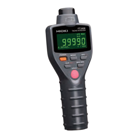
FT3405
FT3406
TACHO HiTESTER
Sept. 2016 Revised edition 4
FT3405A981-04 16-09H
Instruction Manual
EN
Table of
Contents
Previous
Page
Next
Page
1
2
3
4
5
Advertisement
Table of Contents
Need help?
Do you have a question about the FT3405 and is the answer not in the manual?
Ask a question
Questions and answers
Related Manuals for Hioki FT3405
Test Equipment Hioki FT6380 Instruction Manual
Clamp on earth tester (69 pages)
Test Equipment Hioki FT6381 Manual
Clamp on earth tester precautions concerning use of equipment that emits radio waves (2 pages)
Test Equipment Hioki FT3406 Instruction Manual
(50 pages)
Test Equipment Hioki DT4261 Manual
(36 pages)
Test Equipment Hioki FT4310 Instruction Manual
Bypass diode tester (72 pages)
Test Equipment Hioki FT6031 Instruction Manual
Earth tester (77 pages)
Test Equipment Hioki FT6031-03 Instruction Manual
Earth tester (77 pages)
Test Equipment Hioki FT3470-51 Instruction Manual
Magnetic field hitester (116 pages)
Test Equipment Hioki FT3470-52 Instruction Manual
Magnetic field hitester (124 pages)
Test Equipment Hioki FT3151 Instruction Manual
Analog earth tester (132 pages)
Test Equipment Hioki FT6031-50 Instruction Manual
Earth tester (98 pages)
Test Equipment Hioki FT6380-50 Instruction Manual
Clamp on earth tester (70 pages)
Test Equipment Hioki FT6380-90 Instruction Manual
Clamp on earth tester (68 pages)
Test Equipment Hioki FT6031-90 Instruction Manual
Earth tester (77 pages)
Test Equipment Hioki FT6041 Instruction Manual
Earth tester (136 pages)
Test Equipment Hioki 3444 Instruction Manual
Temperature hitester (86 pages)
This manual is also suitable for:
Ft3406
Table of Contents
Print
Rename the bookmark
Delete bookmark?
Delete from my manuals?
Login
Sign In
OR
Sign in with Facebook
Sign in with Google
Upload manual
Upload from disk
Upload from URL


Need help?
Do you have a question about the FT3405 and is the answer not in the manual?
Questions and answers