Table of Contents
Advertisement
Quick Links
Advertisement
Table of Contents

Related Manuals for Iridex IRIS Medical OcuLight SL


Summary of Contents for Iridex IRIS Medical OcuLight SL
- Page 1 ® IRIS Medical ® OcuLight SL/SLx Operator Manual PN 13099D-EN...
- Page 2 ©2005 IRIDEX Corporation. All rights reserved. Published in the USA. Except with the express written permission of IRIDEX, the contents of this manual may not be copied in whole or in part, or reproduced in or transmitted to any other media. All permissible copies, including those translated into another language, must contain the same proprietary and copyright notices as published with the original manual. The manual is provided for instructional use and while every effort has been made to ensure the information is accurate, the information contained within is subject to change without notice. IRIDEX, the IRIDEX logo, IRIS Medical, EndoProbe and SmartKey are registered trademarks of IRIDEX Corporation. TruFocus, DioPexy, G‐Probe, Symphony, CW‐ Pulse, MicroPulse and LongPulse are trademarks of IRIDEX Corporation. All other trademarks are the property of their respective owners. The OcuLight SL and SLx are manufactured using one or more of the following patents: 5,085,492; 5,088,803; 6,540,391; 6,733,490. IRIDEX Corporation, 1212 Terra Bella Avenue, Mountain View, California, 94043‐1824, USA OcuLight SL/SLx Operator Manual PN 13099D-EN...
-
Page 3: Table Of Contents
Table of Contents About IRIDEX …………………………………………………………………………………....5 Overview ………………………………………………………………………………………………5 Contact Information …………………………………………………………………………………5 About the OcuLight SL and SLx ………………………………………………………………………..6 Introduction ……………………………………………………………………………………………6 Potential Adverse Effects ……………………………………………………………………………6 Indications for Use …………………………………………………………………………………….6 About the Components ………..…………………………………………………………………………7 Packing List ……………………………………………………………………………………………7 Component Descriptions ……………………………………………………………………………8 Positioning the SL/SLx ……………………………………………………………………………………9 Temperature and Humidity Considerations ……………………………………………………….9 Electrical Requirements ………………………………………………………………………………9 Physical Location Considerations ………………………………………………………………….10 Rear Panel Connections …………………………………………………………………………………10 Required Connections ……………………….………………………………………………………10 Front Panel Controls and Connections ………………………………………………………………..11 Feature Descriptions…..……………………….……………………………………………………..11 Operating Basics ………………………………………………………………………………………….13 Connecting a Delivery Device ………………………………………………………………………13 Turning On the SL/SLx ………………………………………………………………………………13 Turning Off the SL/SLx … ……………………………………………………………………………14 Emergency Stop ………………………………………………………………………………………14 CW‐Pulse Mode …………………………………………………………………………………………..15 Overview………………………………………………………………………………………………15 ... - Page 4 Maintenance ………………………………………………………………………………………………26 Cleaning the Console…………………………………………………………………………………26 Cleaning the Footswitch …………………………………………………………………………….26 Changing AC Line Fuses …………………………………………………………………………….27 Verifying the Power Calibration ……………………………………………………………………27 Verifying the Power Calibration ……………………………………………………………………28 Warranty and Service …………………………………………………………………………………….30 Safety Information ……………………………………………………………………………………….31 General Measures …………………………………………………………………………………….31 Eye Safety Filters …………………………………………………………………………………….31 Laser Safety Eyewear ………………………………………………………………………………..32 Determining When Safety Eyewear is Required ………………………………………………….32 Safety Features ……………………………………………………………………………………….33 Labeling ……………………………………………………………………………………………………36 Back Panel …………………………………………………………………………………………….36 Manufacturing Date and Serial Number …………………………………………………………..37 Grounding Label ……………………………………………………………………………………..37 Footswitch Label …………………………………………………………………………………….37 Guide to Symbols ……………………………………………………………………………………38 Product Specifications …………………………………………………………………………………39 Treatment Beam ……………………………………………………………………………………..39 Aiming Beam …………………………………………………………………………………………39 General ………………………………………………………………………………………………..39 Appendix A: Table 201 per IEC 60601‐1‐2 ……………………………………………………………41 Appendix B: Table 202 per IEC 60601‐1‐2 …………………………………………………………….42 Appendix C: Decontamination Certificate …………………………………………………………..43 OcuLight SL/SLx Operator Manual PN 13099D-EN...
-
Page 5: About Iridex
About IRIDEX Overview IRIDEX Corporation, headquartered in Mountain View, California, is a leading worldwide manufacturer of solid‐state medical laser systems. The Company develops, manufactures and markets laser systems, delivery instrumentation and related accessories for the ophthalmology, dermatology and veterinary markets. The ophthalmic solid‐state laser systems, marketed under the brand name IRIS Medical, are used to treat a variety of ocular diseases, including the three leading causes of irreversible blindness: macular degeneration, diabetic retinopathy and glaucoma. IRIDEX is an FDA registered medical device manufacturer and complies with current QSR, ISO 13485 and MDD regulations and guidelines. Contact Information Technical Service and Support: Contact IRIDEX via phone: 650.940.4700 Or by email: techsupport@iridex.com To place an Order: Call Toll Free in North America: 800.388.4747 Outside of North America: 650.940.4700 Mailing Address: IRIDEX Corporation 1212 Terra Bella Avenue Mountain View, California 94043‐1824 USA ... -
Page 6: About The Oculight Sl And Slx
About the OcuLight SL and SLx Introduction The IRIS Medical OcuLight SL and OcuLight SLx (SL/SLx) are advanced laser systems. The laser source, power supply, and control panel are combined in a single unit making it portable and easy to stack on a cart, counter or other treatment room instruments. The laser console uses modern semiconductor diode laser technology to produce a visible treatment beam at a nominal wavelength of 810 nm. Diode lasers are efficient and consume very little electrical power, thus the console may be operated from a standard power outlet (115/230V) and does not require water cooling or tube replacements. The laser console uses a solid‐state electronic switching power supply that meets strict U.S. and international performance and safety standards. The laser is controlled by a dedicated microprocessor that continuously monitors the safe function of all subsystems. This manual contains important information on how to unpack, setup, operate, troubleshoot and maintain this system. Keep it available for reference. Potential Adverse Effects Improper use of the SL/SLx can result in adverse effects. Follow the instructions for use described in this operator manual. CAUTION: Federal (U.S.) law restricts this device to sale by or on the order of a physician. CAUTION: Use of controls or adjustments or performance of procedures other than those specified herein may result in hazardous radiation exposure. CAUTION: Laser plume may contain viable tissue particulates. Indications for Use The SL/SLx is indicated for retinal photocoagulation, laser trabeculoplasty, transscleral ... -
Page 7: About The Components
About the Components Packing List Before assembling the SL/SLx, make sure the package contains all ordered components. Check the components carefully before use to ensure no damage occurred during transit. All standard shipments include a laser console, footswitch, medical grade power cord, keys, spare fuses remote interlock plug, laser warning sign, this operator manual and any other accessories that you may have ordered. If there are any items missing from the shipment, please contact IRIDEX customer service immediately. OcuLight SL/SLx Operator Manual PN 13099D-EN... -
Page 8: Component Descriptions
Component Descriptions Console The console contains the laser head, electronics, microprocessor and display panels. The console is the source of laser emission and is the central unit to which all delivery devices attach. Operator Manual The operator manual contains installation, operation, troubleshooting and safety instructions. Keep the manual readily available for reference. Footswitch The footswitch activates the treatment beam when depressed. AC Power Cord The power cord connects the console to an electrical outlet. The plug is medical grade (hospital grade). Unplugging the power cord is the only way to eliminate the flow of all electrical current to the SL/SLx. The key fits into the switch on the front panel and is used to turn the console on and off. Spare Fuses AC line fuses protect the SL/SLx from over‐current conditions. Two spare fuses are provided. OcuLight SL/SLx Operator Manual PN 13099D-EN... -
Page 9: Positioning The Sl/Slx
Positioning the SL/SLx Temperature and Humidity Considerations The SL/SLx should be operated in a well‐ventilated location with a temperature between 10°C (50°F) and 32°C (90°F) with relative humidity between 20 and 80%, non‐ condensing. Electrical Requirements North American Installation The SL/SLx is equipped with a hospital grade (green dot) three‐wire grounding plug. When choosing a location, ensure that a grounding‐type AC receptacle is available, as it is required for safe operation. Installation Outside of North America When the SL/SLx is shipped, IRIDEX customer support will ensure that the power cord included in the packaging is appropriate for local operation. Replacement cords may be ordered to match the IEC320 power inlet with local electrical standards. Always use a three‐wire grounding cord set. Do not alter the power inlet, as it contains protective fusing. Follow local electrical codes before installing the SL/SLx to ensure proper grounding. Physical Location Considerations Place the SL/SLx on a flat table, existing operating room equipment or cart. WARNING: Do not defeat the purpose of the grounding pin. This equipment is intended to be electrically grounded. Contact a licensed electrician if the desired outlet prevents insertion of the grounding pin. CAUTION: Do not position or use the SL/SLx near open flames, compressed oxygen or other flammables. ... -
Page 10: Rear Panel Connections
Rear Panel Connections Power Cord Footswitch Remote Interlock Plug Required Connections Power Cord Plug the female end of the power cord into the AC Power Inlet. Insert the opposite end into a properly grounded electrical outlet. Footswitch Insert the footswitch connector into the connector labeled ʺFootswitchʺ. Ensure the connection is secure. Remote Interlock Insert the remote interlock plug into the remote interlock connector. If desired, this circuit can be used to disable the console if the door to the treatment room is opened. To use the remote interlock, attach the door switch to the screw terminals in place of the shorting wire. If the remote interlock is not properly connected, the message, “No Remote Interlock” will be displayed when the console is turned on. Fuses The SL/SLx is shipped with two independent line fuses installed behind the panel. This panel should be opened only in the event of a blown fuse. Review the Maintenance section of this manual for replacement instructions. NOTE: If you have an OcuLight GL or OcuLight GLx, see your operator manual for instructions on how to control both laser systems with a single footswitch. OcuLight SL/SLx Operator Manual PN 13099D-EN... -
Page 11: Front Panel Controls And Connections
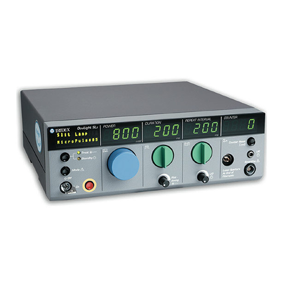
Front Panel Controls and Connections Feature Descriptions Laser Status Display Displays spot size, pulse duration, status and error messages Treat/Standby Toggles the laser status between Treat and Standby. The treatment laser is enabled only when Treat is selected. Mode Multi‐function button. Used to display, activate, confirm and clear messages and settings. Key Switch The key is used to turn the system on and off. Store the key between uses in a secured location to prevent unauthorized use. Emergency Stop Disables the laser and electronic circuits in an emergency. OcuLight SL/SLx Operator Manual PN 13099D-EN... - Page 12 Power Knob Rotate knob to select the desired level of energy to be delivered to the tissue through the selected delivery device. Power level is displayed in milliwatts (mW). Pulse Duration Knob Rotate knob to select the desired pulse duration. Duration is displayed in milliseconds (ms). Pulse Interval Knob Rotate knob to select the desired pulse interval. Repeat interval is displayed in milliseconds (ms). Counter Reset Press button to clear the pulse counter. Fiber Port All delivery devices are connected to the console at the fiber port. Cover the end of the port with the cap between uses to protect it from damage, dirt and debris. LIO Connector Insert the illumination fiber from the LIO to this connector. SmartKey Transmits electrical signals from selected delivery devices to the console. Aiming Beam Brightness Rotate the knob clockwise to increase aiming beam intensity. LIO Illumination Rotate the knob clockwise to increase aiming beam intensity. OcuLight SL/SLx Operator Manual PN 13099D-EN...
-
Page 13: Operating Basics
Operating Basics Connecting a Delivery Device After choosing a delivery device for treatment, insert the fiber‐optic into the fiber port. Make sure the connection is secure; however, do not over‐tighten the nut. If a Slit Lamp Adapter (SLA) or Operating Microscope Adapter (OMA) is used, connect the SmartKey from the device into the receptacle on the front panel of the SL/SLx. Refer to the delivery device operator manual for additional instructions. NOTE: Always check the integrity of the attached delivery device by looking for the presence of the aiming beam. If the aiming beam is not present while the SL/SLx is set to Treat, this may indicate a problem with the fiber optic. If you are in doubt as to the integrity of the fiber optic, measure the treatment laser with a power meter. CAUTION: Do not twist, bend or tightly coil the delivery device fiber optic. Do not bend the fiber optic in loops smaller than 6 inches in diameter. Loosely drape or coil excess length on a flat surface. Keep the fiber‐optic cable away from locations where it may be stepped on. Do not touch the end of the fiber optic as dirt or contaminants on these surfaces may affect optical transmission. Always cap the end of the delivery device when not attached to the SL/SLx. Turning On the SL/SLx Place the key into the key switch and turn clockwise to the on position. The SL/SLx will perform a self‐test and warm‐up for several seconds. During the self‐test, the SL/SLx checks for proper component connections and any inconsistencies with the internal safety system. Following a successful startup sequence, the yellow Standby light will illuminate and the system will enter the CW‐Pulse operating mode. The attached delivery device and spot size, if applicable, are also displayed. OcuLight SL/SLx Operator Manual PN 13099D-EN... -
Page 14: Turning Off The Sl/Slx
Turning Off the SL/SLx After use, turn the key to the off position. Remove and store the key to prevent unauthorized use. The key can only be removed in the off position. After disconnecting a delivery device, insert and secure the fiber port cap to the fiber port. Emergency Stop In the event of an emergency, push the red Emergency Stop button on the front panel. This will immediately disable the laser and all related electronic circuits. The display will read “Emergency Stop!”. To recover following an emergency stop, turn the key to the off position. After a minimum of three seconds, turn the key back to the on position. After restarting, the SL/SLx will be in Standby mode with the power set to 0 mW. OcuLight SL/SLx Operator Manual PN 13099D-EN... -
Page 15: Cw-Pulse Mode
CW-Pulse Mode Overview CW‐Pulse is the default operating mode on the SL/SLx and is active after each key start. In this mode, can be programmed to deliver a single pulse, a series of regularly spaced, intermittent pulses or a continuous pulse. The pulse duration and interval between pulses can be changed over a range of millisecond (10 ‐3 ) values (duration: 10‐9000 ms, interval: 50‐1000 ms). The CW‐Pulse waveform is shown below: Interval Interval (ms) (ms) Duration Duration Time (ms) (ms) (ms) Selecting Treatment Settings Setting the Power At startup, the displayed power is set to 0 mW. Rotate the Power control to select the desired value. Maximum power varies depending on the attached delivery device. NOTE: The power cannot be adjusted while the footswitch is depressed. OcuLight SL/SLx Operator Manual PN 13099D-EN... - Page 16 Selecting the Pulse Duration Rotate the Duration control to set the treatment pulse duration. The display will show the selected duration for each treatment pulse. Selecting the Repeat Interval Rotate the Repeat Interval control to select a single pulse or repeating pulses. To select a single pulse, rotate the knob counterclockwise until the display is blank. With this setting, the SL/SLx will deliver a single timed pulse every time the footswitch is depressed. To select repeating pulses, rotate the control clockwise to the desired value. The pulses will repeat as long as the footswitch is depressed. OcuLight SL/SLx Operator Manual PN 13099D-EN...
-
Page 17: Longpulse Mode
LongPulse Mode Overview In LongPulse, the SL/SLx generates a continuous wave exposure for up to 30 minutes when a large spot delivery device is connected to the laser (Large Spot SLA, Large Spot LIO or Operating Microscope Adapter). The power is constant throughout the duration of each pulse. LongPulse is illustrated in the following diagram: Duration Up to 30 minutes Using LongPulse Mode Entering LongPulse Mode To access the LongPulse operating mode, attach a large spot delivery device to the SL/SLx. Rotate the Duration control until ʺLPʺ displays in the Duration display. Selecting Parameters Continue rotating the Duration control clockwise to select the desired treatment time. The treatment duration period is shown is the top right hand portion of the status display. The lower right hand portion of the status display indicates the OcuLight SL/SLx Operator Manual PN 13099D-EN... - Page 18 amount of time the treatment beam has been activated during the current treatment. Rotate the Power control to the desired level. Initiating Treatment After selecting all desired pulse parameters, press Treat/Standby to select Treat. Direct the aiming beam onto the treatment site. Continuously depress the footswitch throughout the treatment cycle. The console will emit an intermittent audible tone when the treatment laser is activated. The SL/SLx will beep multiple times upon completion of the treatment exposure. In the counter display the shows the amount of energy, in Joules (J), delivered during the treatment. Press Counter Reset to clear the display and initiate another timed treatment cycle. NOTE: If the footswitch is released prior to the completion of a programmed LongPulse treatment, laser emission will stop immediately. NOTE: The repeat interval display will is blank when the SL/SLx is operated in LongPulse mode. Energy Display In LongPulse mode the Counter display shows the total energy (Joules) delivered to the tissue during the treatment session. Press Counter Reset to clear this display. OcuLight SL/SLx Operator Manual PN 13099D-EN...
-
Page 19: Micropulse Mode
MicroPulse Mode (OcuLight SLx Only) Overview MicroPulse is a special operating mode available on the OcuLight SLx. In MicroPulse, the SLx can be programmed to deliver a single pulse or a series of regularly spaced, intermittent pulses. In MicroPulse mode each pulse is subdivided into shorter, regularly spaced microsecond pulses. Consequently the amount of energy delivered to the tissue is much less than with equivalently timed pulses in CW‐Pulse mode. MicroPulse mode may only be used with a slit lamp adapter (SLA). The MicroPulse waveform is illustrated in the following diagram: Pulse Duration Pulse Duration (ms) (ms) Pulse Interval (ms) Time (ms) MicroPulse MicroPulse Duration Interval (ms) (ms) The percentage of time the treatment laser is activated during each pulse is referred to as the duty factor. The duty factor is calculated according to the following formula: MicroPulse Duration × 100% = Duty Factor MicroPulse Duration ... -
Page 20: Using Micropulse Mode
Using MicroPulse Mode To enter MicroPulse mode, press and hold the Mode button for approximately two seconds or until the status display flashes ʺMicroPulseʺ. Press Mode again to activate the MicroPulse menu options. The display shows the first menu option. Selecting a Preset Duty Factor There are three preset duty factor settings in MicroPulse mode: 5%, 10% and 15%. After entering MicroPulse mode any of these settings can be selected by pressing the Treat/Standby button to scroll through the selections. Press Mode to select and confirm the desired selection. NOTE: MicroPulse mode can only be accessed if the Status Display reads ʺTri‐Mode Activatedʺ during the startup sequence. NOTE: MicroPulse mode cannot be used with a Large Spot Slit Lamp Adapter. OcuLight SL/SLx Operator Manual PN 13099D-EN... - Page 21 Selecting a Custom Duty Factor Once in MicroPulse mode, to create a custom duty factor, press Treat/Standby until ʺUser?ʺ is displayed on the status display. Rotate the Duration control to select the MicroPulse duration. Rotate the Repeat Interval control to select the MicroPulse interval. Press Mode to confirm and save the settings. Selecting Power, Pulse Duration and Interval After selecting the desired duty factor, the power, pulse duration (envelope) and pulse interval can be selected by rotating the corresponding controls. Initiating Treatment After selecting all desired pulse parameters, press Treat/Standby to select Treat. Direct the aiming beam onto the treatment site. Press the footswitch to activate the laser. The console will emit an audible tone when the treatment laser is emitted. Press Treat/Standby when not treating patients. OcuLight SL/SLx Operator Manual PN 13099D-EN...
-
Page 22: Customizing The Sl/Slx
Customizing the SL/SLx Adjusting Aiming Beam Intensity Rotate the Aiming Beam Brightness control to adjust the intensity of the red aiming beam when the laser status is set to Treat. To turn the aiming beam off, turn the control fully counter‐clockwise. Adjusting LIO Illumination Rotate the LIO Illumination control to adjust the intensity of the while illumination lamp. This adjustment is active only when an LIO is attached to the fiber port. Adjusting the Volume The SL/SLx emits an audible tone whenever the treatment laser is emitted. Rotate the Volume control to adjust the loudness. For safety reasons, the tone cannot be completely turned off. OcuLight SL/SLx Operator Manual PN 13099D-EN... -
Page 23: User Preferences Menu
User Preferences Menu Entering the User Preferences Menu To access the User Preferences Menu hold the Mode button until the Status Display flashes “User Preferences”. Press Mode again to activate the menu options. The first menu option is the Aiming Laser setting. Changing the Aiming Laser Preference Setting The aiming beam can be programmed to turn on or off while in Standby mode. After entering the User Preferences screen, press Counter Reset to toggle between the two selections. Press Mode to activate the desired selection and exit the User Preferences Menu. Changing the Display Language After entering the User Preferences Menu, press Treat/Standby to access the language preferences screen. Press Counter Reset to cycle through the display language selections. Press Mode to activate the selection and exit the User Preferences Menu. Reviewing the List of Onscreen Messages After entering the User Preferences Menu, press Treat/Standby twice to access the onscreen messages screen. Press Counter Reset to review all available system prompts. There are no user adjustable selections on this screen. Press Mode to exit the User Preferences Menu. OcuLight SL/SLx Operator Manual PN 13099D-EN... -
Page 24: Troubleshooting
Troubleshooting This section provides troubleshooting information for commonly encountered problems. If the problem cannot be mitigated with any of the guidelines below, contact IRIDEX Technical Support. Take note of any message displayed on the screen, the product name, serial number and delivery device used prior to contacting Technical Support. Problem Action No display Ensure that the key switch is on Ensure that all required attachments are connected properly Ensure that electrical service is on Inspect the fuses to ensure they are not blown If after checking the above items, there is still no display, contact IRIDEX Technical Support Poorly illuminated or Ensure that the IRIS Medical delivery absent aiming beam device is connected properly to the SL/SLx Ensure the console is set to Treat Rotate the aiming beam control fully clockwise Ensure the fiber‐optic connector or fiber face is not damaged If possible, connect another IRIS Medical delivery device and set the console to Treat. If the aiming beam is still not visible, contact IRIDEX Technical Support OcuLight SL/SLx Operator Manual PN 13099D-EN... - Page 25 Absent treatment beam Ensure that the remote interlock has not been activated; if so a message indicating the remote interlock is open will be displayed. Ensure that the aiming beam is present and bright. If not, this is a possible indication of a damaged delivery device. Contact IRIDEX Technical Support for assistance. Onscreen Message Action Connect Footswitch Ensure that the footswitch is properly connected. Connect Fiber Connect an appropriate IRIS Medical delivery device, ensure the connection is secure. No Remote Interlock Ensure that the remote interlock is properly connected or jumpered. Ensure that door switches or other circuits are closed, if applicable. Calibration Required Contact IRIDEX Technical Support Emergency Stop To recover following an emergency stop, turn the key to the off position. After several seconds, turn the key back to the on position Call Service Press the Mode button. A description of the fault briefly displays. The console restarts and performs a self‐test, checking for proper component connections and any inconsistencies with the internal safety system. If the message is displayed again, contact IRIDEX Technical Support. Footswitch Stuck Release foot or other object from footswitch ...
-
Page 26: Maintenance
Maintenance Cleaning the Console Keep the SL/SLx enclosure clean by applying soap, mild detergent or isopropyl alcohol (non‐reagent grade) with a soft, moist cloth. Avoid using abrasive or ammonia‐based cleansers. Frequency of cleaning is up to the user and may be dependent upon use and/or environmental conditions. Turn the SL/SLx off prior to initiating any cleaning procedure. CAUTION: Do not open the enclosure. Removing the enclosure and electrical shields may result in exposure to dangerous optical radiation and lethal electrical voltages. There are no user‐ serviceable parts or functions inside the protective covers. NOTE: The SL/SLx enclosure should not be placed within the sterile field of the operating room. Cleaning the Footswitch The footswitch is submersible (IPX8 per IEC 60529). To decontaminate and disinfect the footswitch: 1. Disconnect the footswitch from the laser console. 2. Using water, isopropyl alcohol, or enzymatic detergents with mild pH such as ENZOL ® , remove all traces of blood and other body fluids from all exposed surfaces of the footswitch assembly and the attached cable. 3. Stand the footswitch on the end opposite the cord to drain all fluids. 4. Submerge the footswitch in a CIDEX ® (2.4% glutaraldehyde) solution for 45 minutes minimum at 25°C to achieve a high level of disinfection. 5. Remove the footswitch from the CIDEX solution. 6. Stand the footswitch on the end opposite the cord to drain all fluids. 7. Completely submerge the footswitch in water for a minimum of 1 minute. Repeat this step two more times using clean water for each rinse. ... -
Page 27: Changing Ac Line Fuses
Changing the AC Line Fuses The AC line connection has two independent fuses. The fuse holder is integral to the power inlet on the rear panel of the SL/SLx. To check or change fuses: 1. Remove the power cord from the inlet receptacle. 2. Using a small screwdriver, unlatch and open the fuse panel. 3. Remove and inspect both fuses. 4. If one or both are open, replace them with new fuses, as indicated on the rear panel label. Replacement fuses are IEC 127 2A, 250V, medium time delay, 5 mm x 20 mm. 5. If newly replaced fuses fail, contact IRIDEX Technical Support. Resetting the Circuit Breaker Next to the power inlet is a circuit breaker protecting the power supply transformer from extended overload. The circuit breaker senses high internal operating temperatures, often caused by high ambient temperatures or by greatly exceeding typical clinical usage parameters and overcurrent conditions such as low line voltage. When any of these conditions threaten reliability of the SL/SLx, the circuit breaker button pops out. If the circuit breaker pops: 1) Correct any power input conditions or allow the SL/SLx to cool. 2) Press the circuit breaker reset button. 3) If the circuit breaker is tripped after manually resetting, contact IRIDEX Technical Support. OcuLight SL/SLx Operator Manual... -
Page 28: Verifying The Power Calibration
Peabody, MA 01960 Auburn, CA 95602 978‐535‐5777 530‐888‐5107 www.ophiropt.com www.cohr.com Model: AN/2 Model: FieldMax‐TO To verify the power calibration: 1. Ensure that all persons in the room where the power calibration procedure will be conducted are wearing laser safety eyewear. 2. Connect a properly functioning IRIDEX delivery device. 3. Turn on the SL/SLx 4. Set the Power to 200 mW. 5. Set the Duration to a value greater than 5000 ms. 6. Set the Interval to One Pulse 7. Select an intermediate spot size setting on the delivery device (if applicable). Using very small spot sizes may damage the power meter sensor. 8. Position the power meter in front of the delivery device 9. Center the aiming beam at the middle of the power meter sensor. 10. Adjust the distance between the delivery device and the power meter to produce a 3 to 5 mm diameter spot on the sensor. 11. Place the console in Treat mode. 12. Aim output beam from the delivery device into the power meter, following the power meter instructions for sampling the laser power. ... - Page 29 400‐600 1000 800‐1200 2000 1600‐2400 Model:________________ S/N:_______________________________ Date:_________________ Verification By:_____________________ If any of the readings fall outside the minimum/maximum levels: 1) Check to see if the power meter is operating properly 2) Ensure the beam is directed onto the power meter 3) Repeat the above procedure with a different IRIS Medical delivery device (if possible) If the delivered power is still not within the acceptable minimum/maximum levels, the SL/SLx requires repair. Contact a local IRIDEX Technical Support Representative for service instructions. Any recalibration of the SL/SLx must be performed by authorized IRIDEX personnel. OcuLight SL/SLx Operator Manual PN 13099D-EN...
-
Page 30: Warranty And Service
Warranty and Service Warranty The SL/SLx console carries a standard factory warranty. The warranty covers all parts and labor required to correct problems with materials or workmanship; however the warranty is voided if the enclosure is removed by anyone other than certified IRIDEX service personnel. Product Registration Please complete and forward the product registration card to IRIDEX. Prompt reply will ensure the console is tracked by customer service. The registered owner will be kept informed on any product notices and/or upgrades. Service and Technical Support IRIDEX is committed to supporting installations worldwide. Contact IRIDEX Technical Support if you require assistance with the SL/SLx. OcuLight SL/SLx Operator Manual PN 13099D-EN... -
Page 31: Safety Information
Safety Information General Measures This section addresses the safe use and operation of the SL/SLx. Failure to comply with this safety information may result in harm to the physician, patient, or bystanders. This device is intended for use by qualified physicians only. The applicability of the equipment and treatment technique is the sole responsibility of the physician. Do not use this device if it is believed to not be functioning properly. Before operating the laser, carefully observe the following protective measures: Never look directly into the laser aperture or at laser energy scattered from specular surfaces. Avoid directing the treatment beam at highly reflective surfaces or unintended objects. Ensure that all persons in the treatment room are wearing laser safety eyewear. Never substitute prescription eyewear for laser safety eyewear. Do not use the laser in the presence of explosives, compressed oxygen, volatile anesthetics or other flammable materials. Always keep the laser in the Standby mode when not treating patients. Turn the console off and remove the key between procedures to prevent unauthorized use. Do not open the SL/SLx enclosure. Only factory‐trained personnel are qualified to examine and repair the interior of the SL/SLx. CAUTION: Removal and/or opening of the enclosure and electrical shields may result in exposure to dangerous optical radiation and lethal electrical voltages. There are no user‐ serviceable parts or functions inside the enclosure. Eye Safety Filters Eye safety filters provide protection from backscattered laser emissions. IRIS Medical slit lamp adapters (SLA) and laser indirect ophthalmoscopes (LIO), have integral eye safety filters permanently installed in the viewing path. When using the SL/SLx for intraocular procedures, a separate discrete eye safety filter assembly must be installed into all viewing paths of the operating microscope. All IRIS Medical eye safety filters have an optical density (O.D.) sufficient to permit long‐term viewing of diffuse 810 nanometer light at Class I levels, per ANSI Z136.1:2000. OcuLight SL/SLx Operator Manual PN 13099D-EN... -
Page 32: Laser Safety Eyewear
Laser Safety Eyewear In order to adequately protect the eyes of all persons in the treatment room, all occupants must wear safety glasses with a minimum O.D. of 4.0 at 800‐840 nm. Verify that the safety glasses chosen for use with the SL/SLx are appropriate for use by checking the O.D. and wavelength rating on the frames. Additional glasses may be purchased through IRIDEX. Determining When Safety Eyewear is Required Safety eyewear is required when the laser is in use and individuals are physically located inside the Nominal Ocular Hazard Distance (NOHD). The NOHD is the maximum distance from the laser at which damage to the eye can occur. Any individuals within this distance from the laser must wear protective eyewear or risk unintended eye damage. The NOHD varies depending upon the type of delivery device attached to the SL/SLx. The formula to calculate worst case NOHD is given by the following: Φ ⎛ ⎞ ⎛ ⎞ ⋅ ⎟ ⎜ ⎜ ⎟ NOHD(m) ⋅ ⎝ ⎠ ⎝ π ⎠ Where: N.A.= equals the Numerial Aperture of the delivery device ... -
Page 33: Safety Features
The range of worst case NOHD values calculated for all IRIS Medical delivery devices is included in the following table: Numerical MPE Maximum NOHD Delivery Device Aperture (W/m ) Power (W) (m) (N.A.) G‐Probe 16.8 0.25 3.0 1.6 EndoProbe 16.8 0.10 2.0 3.3 SLA 16.8 0.04 2.0 8.3 (500 micron spot) DioPexy Probe 16.8 0.03 2.0 11.0 Large Spot SLA 16.8 0.03 2.0 11.0 LIO 16.8 ... - Page 34 Remote Interlock An external interlock circuit is located on the back panel. The circuit can be used to disable the console if the treatment room door is opened during treatment. For locations that do not require an external interlock, an interlock jumper is provided. Key Switch The SL/SLx operates only when the proper key is in place. The key cannot be removed while the key switch is turned to the On position. Laser Emission Indicator When the footswitch is depressed, an audible tone indicates that the console is delivering laser energy. The audible indicator volume may be adjusted but not turned off. Time Delay When Activating Laser The console delivers laser energy only when Treat is selected and the footswitch is depressed. When the status of the console is changed from Standby to Treat, the footswitch is disabled for 3 seconds to help prevent unintentional delivery of energy. Beam Attenuator The SL/SLx includes an electronic attenuator that prevents the treatment beam from exiting the console until all requirements for emission are met and the footswitch is depressed. Viewing Optics Operating microscopes used with the SL/SLx must be equipped with a fixed safety filter assembly, which is installed in the viewing path of the microscope. When properly installed, the IRIS Medical eye safety filters will protect anyone viewing through the microscope from laser radiation in excess of CDRH Class I levels. The IRIS Medical Laser Indirect Ophthalmoscope (LIO) and Slit Lamp Adapters (SLA) include a fixed filter, which ensures any laser radiation returned to the physician’s eyes during clinical use is below the Class I limit. OcuLight SL/SLx Operator Manual PN 13099D-EN...
- Page 35 Location of the Controls The laser controls for the SL/SLx are located on the front of the console and positioned at a safe distance from the laser aperture. Manual Restart The SL/SLx immediately disables all laser circuits upon interruption of the Remote Interlock circuit or loss of line power. In this event, the SL/SLx must be manually reset by cycling the keyswitch off and on. Internal Power Monitor The power emitted from the delivery device is indicated on the display. Two internal power monitors independently measure the laser power before energy is emitted through the delivery device. If the measurements from the two monitors differ significantly, the console will display a warning message instructing the user to call IRIDEX Technical Support. Footswitch Depressing the footswitch, while in Treat, delivers the treatment beam. If the footswitch is damaged or improperly connected, Treat cannot be selected and the Connect Footswitch message will be displayed. The footswitch can be safely immersed and cleaned (in compliance with IPX8 per IEC 60529), and is shrouded for maximum safety (in compliance with ANSI Standard Z136.3, 4.3.1). Long Term Reliability A crystal oscillator controls the timing of the Pulse Duration. Initial uncertainty in the measurement is less than 1 ms. The level of uncertainty is not expected to increase or decrease over the life of the product. Power is automatically controlled by optical sampling circuits. Initial uncertainty in the measurement is less than 5% of the requested power, including laser power meter uncertainties. This uncertainty is not expected to increase or decrease by more than 1% of the requested power over the life of the product. Laser delivery is affected by many parameters, just one of which is the accurate control of optical energy. Other factors include cleanliness and condition of delivery devices as well as alignment accuracy. OcuLight SL/SLx Operator Manual...
-
Page 36: Labeling
Labeling Back Panel OcuLight SL/SLx Operator Manual PN 13099D-EN... -
Page 37: Manufacturing Date And Serial Number
The reliability of the ground connection can only be assured when this device is connected to an approved mating receptacle marked for hospital use and installed in accordance with the appropriate Electrical Codes for medical occupancy. Footswitch Label IPX8 IRIDEX 12167 OcuLight SL/SLx Operator Manual PN 13099D-EN... -
Page 38: Guide To Symbols
Guide to Symbols Pulse Power Attention! Pulse Duration Volume Pulse Interval Footswitch Aiming Beam LIO Illumination On Treat Off Standby 2 x 2A H ETL Mark Fuse 250V STOP CE Mark ... -
Page 39: Product Specifications
Product Specifications Treatment Beam Wavelength: 810 nm (nominal) Laser Class: Class IV, per CFR 1040.10 Class4 per IEC 60825‐1 Source: Solid‐state diode Output Power: 50–3000 mW (SLx), dependent upon attached delivery device 50‐2000 mW (SL), dependent upon attached delivery device Duration CW‐Pulse Mode‐ 10 ms‐9000 ms in 29 increments and continuous pulse up to 60 s MicroPulse Mode (SLx only)‐ 0.10‐1.0 ms in 0.05 ms increments LongPulse Mode‐ 10 seconds to 30 minutes in 26 increments Repeat Interval: 50‐1000 ms in 11 increments and Single Pulse Aiming Beam Wavelength: 650 nm (nominal), coaxial with treatment beam Source: Solid‐state diode Output Power: <1 mW maximum General Dimensions: 30 cm W x 30 cm D x 10 cm H (12 in x 12 in x 4 in) Mass: ... - Page 40 Onscreen English, Dutch, French, German, Greek, Italian, Portuguese, Languages: Spanish Compatible Compatible with the following IRIS Medical Devices: Delivery Infrared Slit Lamp Adapters (SLA), Laser Indirect Devices: Ophthalmoscopes (LIO), EndoProbe Handpieces, DioPexy Probe, G‐Probe, Symphony (SLx only) and Operating Microscope Adapters (OMA). Contact IRIDEX Customer Service for complete information regarding delivery device compatibility with the SL/SLx Operating Mode Delivery Device CW‐Pulse MicroPulse LongPulse Compatibility: • • Slit Lamp Adapter (SLA) • • Large Spot SLA ...
-
Page 41: Appendix A: Table 201 Per Iec 60601-1-2
Appendix A- Table 201 per IEC 60601-1-2 Guidance and manufacturer’s declaration‐electromagnetic emissions The SL/SLx is intended for use in the electromagnetic environment specified below. The customer or the user of the SL/SLx should assure that it is used in such an environment. Emissions test Compliance Electromagnetic environment ‐ guidance RF emissions The SL/SLx uses RF energy only for its internal functions. Therefore, its RF emissions are very low CISPR 11 Group 1 and are not likely to cause any interference in nearby electronic equipment. The SL/SLx is suitable for use in all establishments, RF emissions Class B including domestic establishments and those directly CISPR 11 connected to the public low‐voltage power supply Harmonic network that supplies buildings used for domestic emissions Class B purposes. IEC 61000‐3‐2 Voltage fluctuations/ Complies flicker emissions IEC 61000‐3‐3 OcuLight SL/SLx Operator Manual PN 13099D-EN... -
Page 42: Appendix B: Table 202 Per Iec 60601-1-2
Appendix B- Table 202 per IEC 60601-1-2 Guidance and manufacturer’s declaration‐electromagnetic immunity The SL/SLx is intended for use in the electromagnetic environment specified below. The customer or the user of the SL/SLx should assure that it is used in such an environment. Immunity test IEC 60601 Compliance level Electromagnetic environment ‐ guidance Test level Electrostatic Floors should be wood, concrete or ±6 kV contact ±6 kV contact discharge (ESD) ceramic tile. If floors are covered ±8 kV air ±8 kV air with synthetic material, the relative IEC 61000‐4‐2 humidity should be at least 30%. Electrical fast ±2 kV for power ±2 kV for power Mains power quality should be that transient/burst supply lines supply lines of a typical commercial or hospital environment. IEC 61000‐4‐4 ±1 kV for ±1 kV for input/output lines input/output lines ... -
Page 43: Appendix C- Decontamination Certificate
____________________________________ ____________________________________ Model ________________________________ Model _________________________________ ______________________________________ _______________________________________ Serial # ________________________________ Serial # ________________________________ IRIDEX RMA # _________________________ IRIDEX RMA#__________________________ Typed/Printed Name ___________________ Typed/Printed Name ____________________ ______________________________________ _______________________________________ Signature ______________________________ Signature ______________________________ OcuLight SL/SLx Operator Manual PN 13099D-EN...
Need help?
Do you have a question about the IRIS Medical OcuLight SL and is the answer not in the manual?
Questions and answers