Sign In
Upload
Download
Table of Contents
Contents
Add to my manuals
Delete from my manuals
Share
URL of this page:
HTML Link:
Bookmark this page
Add
Manual will be automatically added to "My Manuals"
Print this page
×
Bookmark added
×
Added to my manuals
Manuals
Brands
Iridex Manuals
Medical Equipment
IQ 577
Operator's manual
Iridex IQ 577 Operator's Manual
Laser systems
Hide thumbs
1
2
Table Of Contents
3
4
5
6
7
8
9
10
11
12
13
14
15
16
17
18
19
20
21
22
23
24
25
26
27
28
29
30
31
32
33
34
35
36
37
38
39
40
41
42
43
44
45
46
47
48
49
page
of
49
Go
/
49
Contents
Table of Contents
Troubleshooting
Bookmarks
Table of Contents
Table of Contents
1 Introduction
Compatible Delivery Devices
Pulse Types
References
Indications for Use - IQ 577 Models
Indications for Use - IQ 532 Models
Warnings and Cautions
IRIDEX Corporation Contact Information
2 Setup
Unpacking the System
Choosing a Location
Connecting the Components
3 Operation
Front Panel Controls
Powering the Laser on and off
Treating Patients
Using the Laser System
4 Troubleshooting
General Problems
Error Messages
5 Maintenance
Inspecting and Cleaning the Laser
Inspecting and Cleaning the Footswitch
Verifying the Power Calibration
6 Safety and Compliance
Protection for the Physician
Protection for All Treatment Room Personnel
Safety Compliance
Labels
Symbols (as Applicable)
Specifications
7 Wireless Footswitch and EMC
Setting up the Wireless Footswitch
Testing the Batteries
EMC Safety Information
EMC Requirements for Console and Accessories
Advertisement
Quick Links
1
Compatible Delivery Devices
2
Indications for Use - Iq 577 Models
3
Indications for Use - Iq 532 Models
4
Error Messages
5
Maintenance
6
Verifying the Power Calibration
Download this manual
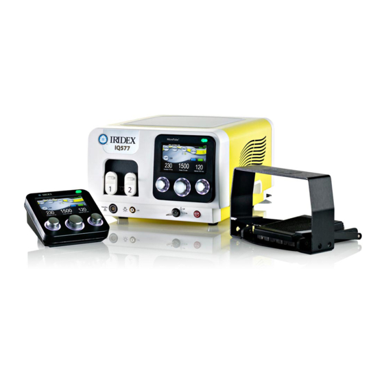
IRIDEX IQ 577
/IQ 532
®
®
Laser Systems
Operator Manual
Table of
Contents
Previous
Page
Next
Page
1
2
3
4
5
Advertisement
Table of Contents
Need help?
Do you have a question about the IQ 577 and is the answer not in the manual?
Ask a question
Questions and answers
Related Manuals for Iridex IQ 577
Medical Equipment IRIDEX IQ 532 Operator's Manual
Laser systems (49 pages)
Medical Equipment Iridex IRIS Medical OcuLight SL Service Manual
(42 pages)
Medical Equipment Iridex IRIS Medical OcuLight SL Operator's Manual
(43 pages)
Medical Equipment Iridex 577 Operator's Manual
Laser system (85 pages)
Medical Equipment Iridex OcuLight SL Operator's Manual
(36 pages)
Medical Equipment IRIDEX MicroPulse P3 Instructions For Use Manual
Device instrumentation (8 pages)
Medical Equipment Iridex Oculight SL Operator's Manual
(36 pages)
Medical Equipment IRIDEX OcuLight GL Operator's Manual
(38 pages)
Medical Equipment IRIDEX EndoProbe Series Operator's Manual
(19 pages)
Medical Equipment Iridex MicroPulse P3 Device Instructions For Use Manual
(14 pages)
Medical Equipment Iridex TruFocus LIO+ Operator's Manual
(38 pages)
Medical Equipment Iridex G-Probe Operator's Manual
(17 pages)
Medical Equipment Iridex OcuLight Symphony Operator's Manual
(68 pages)
Medical Equipment Iridex EndoProbe Operator's Manual
(44 pages)
Medical Equipment Iridex LIO Plus Operator's Manual
(21 pages)
Medical Equipment Iridex PASCAL Synthesis Operator's Manual
Ophthalmic scanning laser system (141 pages)
This manual is also suitable for:
Iq 532
Table of Contents
Print
Rename the bookmark
Delete bookmark?
Delete from my manuals?
Login
Sign In
OR
Sign in with Facebook
Sign in with Google
Upload manual
Upload from disk
Upload from URL


Need help?
Do you have a question about the IQ 577 and is the answer not in the manual?
Questions and answers