Schartec Porte 300 User Manual
Swing gate opener 24v dc for residential use only
Hide thumbs
Also See for Porte 300:
- User manual (13 pages) ,
- Fitting instructions manual (36 pages) ,
- Manual (42 pages)

Related Manuals for Schartec Porte 300


Summary of Contents for Schartec Porte 300
- Page 1 Anleitung Porte 300 Drehtorantrieb 24V DC für den privaten Bereich English manual begins on Page 13 Signalleuchte Drucktaster Steuerung Tor 2 Tor 1...
-
Page 2: Table Of Contents
Inhalt Wichtige Sicherheitshinweise Introduction 2.1 Übersicht & Anwendung 2.2 Im Lieferumfang Enthalten Installation Vorbereitungen Installation des Steuerungskastens Vorbereitung Installation der Antriebsarme/ Motoren Installation der Motoren Technische Daten EU-Einbauerklärung... -
Page 3: Wichtige Sicherheitshinweise
1. Wichtige Sicherheitshinweise 1.1 Bestimmungsgemäße Verwendung Der Schartec Porte 300 Drehtor-Antrieb ist ausschließlich für den Betrieb von leichtgängigen Drehtoren im privaten, nicht gewerblichen Bereich vorgesehen. Die maximal zulässige Torgröße und das maximale Gewicht dürfen nicht überschritten werden. Das Tor muss sich leicht von Hand öffnen und schließen lassen. - Page 4 1.7 Weitere wichtige Hinweise 1. Bitte lesen und befolgen Sie alle Sicherheitshinweise und Einbauempfehlungen. 2. Der Torantrieb ist den örtlichen Bestimmungen entsprechen entworfen und hergestellt worden. Der Installateur muss mit den örtlichen Vorschriften in Bezug auf die Installation des Drehtorantriebs vertraut sein.
-
Page 5: Introduction
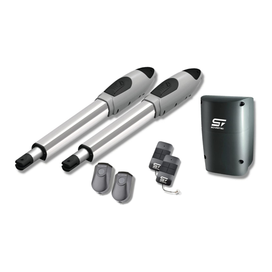
Betrieb des Drehtores müssen die beiden Motoren mit dem beiliegenden Schlüssel entriegelt werden. 2.2 Im Lieferumfang enthalten Bild 2 A) 2 Stk. Schartec Porte 300 Motoren B) Steuerung Porte P190 C) Lichtschranke Schartec SPC D) 2 Stk. Handsender Schartec SR-4... -
Page 6: Installation Vorbereitungen
3. Installation Vorbereitungen Werkzeuge für die Installation Bitte stellen Sie sicher, dass die unten aufgeführten Werkzeuge zur Installation vorhanden sind. Bild 3 4. Installation des Steuerungskastens 1. Lösen Sie die Schrauben des Deckels und nehmen Sie diesen ab. 2. Die vier Befestigungspunkte für den Steuerungskasten befinden sich genau an der Position an der der Deckel verschraubt ist. -
Page 7: Vorbereitung Installation Der Antriebsarme/ Motoren
5. Vorbereitung Installation der Antriebsarme/ Motoren Hinweise zum Betrieb des Antriebs Der Drehtorantrieb Porte 300 ist für ein maximales Torflügelgewicht von 300 kg (je Flügel), eine maximale Torflügelbreite von 3 Meter (je Flügel), und eine maximale Torflügelhöhe von 2 Meter (je Flügel) ausgelegt. Der Öffnungswinkel beträgt bis zu 110°. - Page 8 Achtung! A-Maß und B-Maß müssen zwingend eingehalten werden in dem angegebenen Bereich 130 - 190 mm (siehe Bild 7). Ansonsten kein einwandfreier Torlauf möglich. Folge: Steuerung stoppt Antrieb bereits während der Lernfahrt oder Antrieb reversiert im Betrieb. Porte 300 Bild 6 (Luftaufnahme) Bild 7 10) "C"...
-
Page 9: Installation Der Motoren
6. Installation der Motoren 1) Wählen Sie die richtige Montageposition der Motoren. 2) Prüfen Sie ob die Montageflächen für die Halterungen eben und nach Wasserwaage ausgerichtet sind. 3) Legen Sie die Kabel für die Stromversorgung der Motoren. 4) Montieren Sie die Motorhalterungen so wie es auf Bild 17 zu sehen ist. 5) Öffnen Sie die beiden Schrauben am Motor und entfernen Sie die Abdeckung wie auf Bild 9. - Page 10 12) Heben Sie den Motor an und stecken Sie die Schraube in die vordere Motorhalterung. 13) Entfernen Sie die Motorabdeckung, lösen Sie die Schraube und entfernen Sie den Bolzen. Siehe Bild 15. Heben Sie nun den hinteren Teil des Motors an und bewegen Sie den Torflügel bis der Motor an der hinteren Halterung fixiert werden kann wie auf Bild 16.
-
Page 11: Technische Daten
21) Verwenden Sie den Entriegelungsschlüssel und drehen Sie die Entriegelung gegen den Uhrzeigersinn bis zum Anschlag. Bild 21 Bild 23 Bild 22 7. Technische Daten Porte 300 Motor 24 V DC mit mech. Entriegelung Getriebe Typ Wurmgetriebe Spitzenkraft 3000 N... -
Page 12: Eu-Einbauerklärung
Schartec eine Marke der bau-shop-24 GmbH Fritz-Müller-Strasse 119 73730 Esslingen, Germany erklärt hiermit, dass die Torantriebe Porte 150, Porte 300, & Jet 500 in Übereinstimmung mit der − Maschinenrichtlinie 2006/42/EG − Niederspannungsrichtlinie 2014/35/EU − Richtlinie für elektromagnetische Verträglichkeit 2014/30/EU − RoHS Richtlinie 2011/65/EU −... - Page 13 Porte 300 Users Manual Swing Gate Opener 24V DC for residential use only Signal Light Push-button Control Box Gate 2 Gate 1...
- Page 14 Contents Important Safety Information Introduction 2.1 Overview and Application 2.2 Scope of Delivery Installation Preparations Installing the Control Box Installation preparation of drive arms / motors Installing the Motors Technical specifications EU-Declaration of Incorporation...
-
Page 15: Important Safety Information
1. Important Safety Information 1.1 Intended Use The Schartec Porte 300 swing gate opener is intended exclusively for the operation of smooth-running swinging gates in private, non-commercial areas. The maximum permissible gate size and maximum weight must not be exceeded. The gate must be easy to open and close by hand. Regional wind loads must be taken into account when using gate fillings/panels (EN 13241-1). - Page 16 1.7 Further important information 1. Please read and follow all safety instructions and installation recommendations. 2. The gate operator has been designed and manufactured according to local regulations. The installer must be familiar with local regulations regarding the installation of the swing gate operator. 3.
-
Page 17: Introduction
230 V. For manual operation of the swing gate, the two motors must be unlocked with the enclosed key. 2.2 Scope of Delivery Figure 2 A) 2 pcs. Schartec Porte 300 Motors B) Control Box Porte P-190 C) Photocells Schartec SPC D) 2 pcs. Remote Controls Schartec SR-4... -
Page 18: Installation Preparations
3. Installation Preparations Tools needed for Installation Please make sure that the tools listed below are available for installation. Figure 3 4. Installing the Control Box 1. Loosen the screws to the cover and remove it. 2. The four fastening points for the control box are exactly at the position at which the cover is screwed on. CAUTION! Never drill through the control box housing, otherwise your guarantee and warranty will be forfeited. -
Page 19: Installation Preparation Of Drive Arms / Motors
Notes on use of the operator The Porte 300 swing gate operator is designed for a maximum gate weight of 300 kg (per leaf), a maximum gate width of 3 meters (per leaf), and a maximum gate height of 2 meters (per leaf). The opening angle is up to 110°. - Page 20 130 - 190 mm (see Fig. 7). Otherwise, system learning will not be possible. Result: Control boards stops the motors during the learning run or motors reverse during operation. Porte 300 Figure 6 (Aerial View) Figure 7 10) "C" value is 139 mm 11) "D"...
-
Page 21: Installing The Motors
6. Installation of the Motors 1) Choose the correct mounting position of the motors. 2) Check that the mounting surfaces for the brackets are level. 3) Insert the cables for the power supply to the motors. 4) Install the motor mounts as shown in Figure 8. 5) Remove the two screws on the motor and remove the cover as shown in Figure 9. - Page 22 12) Lift the motor and insert the screw into the front motor mount. 13) Remove the motor cover, loosen the screw and remove the bolt. See Figure 15. Now lift the rear of the motor and move the gate until the motor can be locked to the rear bracket as shown in Figure 16. Slide the bolt through the hole provided in the motor and through the rear bracket.
-
Page 23: Technical Specifications
7. Technical data Porte 300 Motor 24 V DC with mechanical unlocking release Gear Type Worm Gear Peak Force 3000 N Motor Travel Length 350 mm Power Supply 24 V DC Max. Working Current 4 A for max. 10 seconds Max. -
Page 24: Eu-Declaration Of Incorporation
GmbH Fritz-Müller-Strasse 119 73730 Esslingen, Germany hereby declares that the door operators Porte 150, Porte 300, & Jet 500 were developed, constructed, and produced in agreement with − Machinery Guidelines 2006/42/EG − Low-Voltage Directive 2014/35/EU − Directive for Electromagnetic Compliance 2014/30/EU −...
Need help?
Do you have a question about the Porte 300 and is the answer not in the manual?
Questions and answers