Table of Contents
Advertisement
Advertisement
Table of Contents

Related Manuals for FKG Rooter Universal


Summary of Contents for FKG Rooter Universal
- Page 1 User Manual...
- Page 2 Introduction Thank you for purchasing the device. For optimum safety and performance, read this manual thoroughly before using the device and pay close attention to warnings and notes. Keep this manual in a handy place for quick and easy reference. Notice The trademarks mentioned in this manual are the property of their legally registered companies.
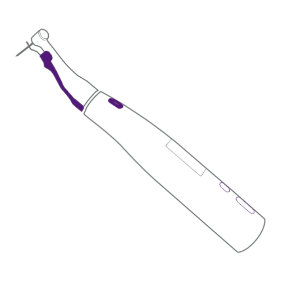
- Page 3 Fig. A Components and Accessories AC Adapter Tester Motor Handpiece Battery Charger (CX265-28 (type C) (CX265-67) 50.0007.011 (type I) 50.0007.010 (type G)) Test Wire A Test Wire B File Clip Lip Hook (CX265-63) (CX265-64) (CX265-52) (CX265-17) 16:1 Contra-angle Protective Sleeve Lighting Device (C4-2M) (CX265-65)
- Page 4 Fig. C Contra Angle & File connection Fig. D Accessory Connection Install Remove...
- Page 5 Fig. E Apex Locator Mode Test Wire Jack Fig. F Multi-function Mode...
- Page 6 Fig. G Charging Fig. H Replace the battery Rubber Cover...
-
Page 7: Table Of Contents
Table of Contents Attention ..............1 Attention Customers ................1 Prevent Accidents ................1 Disclaimer ..................3 In Case of Accident ................3 User Qualifications ................3 Intended Used ...................4 Usage ................5 Operation and Storage Environments ..........5 Operation Modes ................5 Power On/Off ..................5 Endo Motor Mode ................6 Apex Locator Mode .................14 Multi-function Mode ...............19 EMR ................21... - Page 8 Calibration and Settings ...........28 Enter Setting Mode ................28 Calibration ..................28 Set Dominant Hand ................29 Reset Memories to Original Default Settings ........30 Cleaning, Disinfection and Sterilization ....31 Troubleshooting ............36 Technical Specifications ..........37 Symbols..............38 Guarantee .............39 Disposal of Medical Devices ........39 EMC ...............40...
-
Page 9: Attention
1. Attention 1.1 Attention Customers Do not fail to receive clear instructions concerning the various ways to use this device as described in this accompanying Operation Instructions. 1.2 Prevent Accidents Most operation and maintenance problems result from insufficient attention being paid to basic safety precautions and not being able to foresee the possibilities of accidents. - Page 10 Do not use this device for anything other than its specified dental treatment purpose. WARNING No modification of this device is allowed. PROHIBITION Do not use this device on patients who have implanted pacemakers or defibrillators. IMPORTANT PRECAUTIONS These caution remarks are especially critical for safe operation and use. Do not use the wireless transmission devices listed below in the examination area: a) Cell phone terminals.
-
Page 11: Disclaimer
1.3 Disclaimer Manufacturer will not be responsible for accidents, device damage, or bodily injury resulting from: a) Repairs made by personnel not authorized by manufacturer. b) Any changes, modifications, or alterations of its products. c) Maintenance or repairs using parts or components other than those specified by manufacturer and other than in their original condition. -
Page 12: Intended Used
c) Language Understanding: English (Intended for professional use as described above) d) Experience: Experienced person with operating endodontic instrument. 1.6 Intended use The Rooter® Universal is an electro-medical device intended to drive mechanical instruments intended for dental root canal treatment (files). In addition, it is intended to help to determine the working length (apex locator functionality). -
Page 13: Usage
2. Usage CAUTION: • Do not expose the device to direct sunlight for an extended period of time. • If the device has not been used for some time, make sure it works properly before using it again. • Refer to the contra-angle operation manual for all operations regarding the contra-angle. -
Page 14: Endo Motor Mode
CAUTION: • Have components been sterilized? (Refer to chapter7) • Is the battery sufficiently charged? (Refer to chapter 5.1) Endo Motor Mode If not any test wire connected to the device, it’s in Endo Motor Mode. Please refer to Fig. C, D 2.4.1 Connect the Components a) Connect contra angle Line up the projection inside the contra angle with the notch inside the... - Page 15 • Never use stretched, deformed or damaged files. • Make sure the file is all the way in. Give the file a light tug to confirm it is securely held in place. If the file is not securely placed, it could come out and injure the patient.
- Page 16 2.4.2 LCD Display File Manufacturer File File System Standby 1 Battery Power Speed Rotary Direction Torque Limit Standby 2 NOTE: Some preset files have automatic parameters. If such a file has been selected, the speed and torque value will display “auto”.
- Page 17 2.4.3 File systems libraries The device contains libraries of file systems with preset parameters. a) Hold down to enter selection interface and press again to select the file systems library. NOTE: The change will be saved automatically. Press to exit the selection interface.
- Page 18 2.4.4 Start Working a) Start Motor Press to start the motor handpiece and press again to stop it. The lighting device will continue to illuminate while the motor handpiece is running. WARNING: If the contra angle’s file release button is pressed against the teeth opposite the one being treated, the file could come out and injure the patient.
- Page 19 2.4.5 Auto Reverse If, during operation the load reaches the preset torque limit value, the motor handpiece will automatically rotate in the reverse direction. When the load is reduced, the motor handpiece returns to normal forward rotation automatically. Load within the Load beyond the When the load is reduced, torque limit value.
- Page 20 • In User Recipro file system, torque cannot be changed. • In all FKG file systems, rotation direction, speed, torque and rotation angle cannot be changed. (fixed settings) a) Hold down until the Speed flash and press again to select speed or torque to adjust.
- Page 21 2.4.7 User library file system The device contains two user-created file systems: Rotary File and Recipro File. Users can set parameters by themselves. a) Rotary File (4 memories preset at original default settings: 1000rpm FW 1.5Ncm) To change speed and torque refer to 2.4.6 b) Recipro File (1 memory preset at original default settings: +30 /-150 150rpm) speed and rotation angle.
-
Page 22: Apex Locator Mode
2.5 Apex Locator Mode While the test wire A is connected to the motor handpiece, the device Please refer to Fig. E enters the Apex Locator Mode automatically. 2.5.1 Connect the Components a) Connect lip hook and file clip b) Connect file c) Connect test wire A CAUTION: •... - Page 23 2.5.2 LCD Display Apex DR's CHOICE 2.5.3 Measurement a) Hook the lip hook in the corner of the patient's mouth. WARNING: • Never use an electric scalpel when the lip hook is hooked in the patient’s mouth. These devices emit electrical noise that could interfere with accurate measurement or cause the device to malfunction.
- Page 24 b) Slowly insert the measuring file into the canal. Bar in meter show the location of the file tip. The color of the display: There is slow beeping sound between bars 6 - 11. There is fast beeping sound between bars 15 - 17. A sustained beep sounds when the file tip reaches or exceeds the DR's CHOICE.
- Page 25 WARNING: • In some cases such as a blocked root canal, a measurement cannot be made. (Refer to chapter3) • Accurate measurement is not always possible, especially in cases of abnormal or unusual root canal morphology. Make sure to take an X-ray to check the results.
- Page 26 2.5.4 Set the DR's CHOICE This feature enables to mark an individual predetermined reference position at the required distance from the apex. When DR's CHOICE apical arrow is set, clear visual and audio indication is given that the file has reached this pre-selected position. To set the DR's CHOICE, follow the next step: Hold down until the apex setting icon flash.
-
Page 27: Multi-Function Mode
2.6 Multi-function Mode While the test wire B is connected to the motor handpiece, the device Please refer to Fig. C, D, F. enters the Multi-function Mode automatically. 2.6.1 Connect the Components a) Connect lip hook b) Connect test wire B c) Connect contra angle and file. - Page 28 2.6.2 LCD Display Standby 1 Standby 2 Working 2.6.3 File systems library (Refer to chapter 2.4.3) 2.6.4 Start Working (Refer to chapter 2.4.4) 2.6.5 Auto Reverse (Refer to chapter 2.4.5) NOTE: When the file reaches the apex position set by the user, the motor will automatically rotate in the reverse direction.
-
Page 29: Emr
3. EMR (Electric Measurement of Root canal length) Accurate measurement cannot be obtained with the root canal conditions shown below. Root canal with a large apical foramen Root canal that has an exceptionally large apical foramen due to a lesion or incomplete development cannot be accurately measured. - Page 30 Re-treatment of a root filled with gutta-percha The gutta-percha must be completely removed to eliminate its insulating effect. After removing the gutta-percha, pass a small file all the way through the apical foramen and then put a little saline in the canal, but do not let it overflow the canal opening.
-
Page 31: Operation Check
4. Operation Check 4.1 Check with Tester a) Connect the tester to the test wire jack on the back of the motor handpiece. b) Check that the canal length indicator bars light up between number 0.2 and number 0.5. WARNING: If the canal length indicator bars does not light up between number 0.2 and number 0.5, an accurate measurement cannot be made. - Page 32 b) Check Test Wire B Touch the lip hook with the file in the contra angle and check that all the bars on the meter in the display light up. WARNING: Check the device’s function before use with each patient. If all the indicator bars do not light up, an accurate measurement cannot be made.
-
Page 33: Battery And Charging
5. Battery and Charging 5.1 Battery Power The number of bars shows how much power is left. NOTE: The display of low voltage: Charge the battery as soon as the indicator gets down to only one bar. 5.2 Battery Charging Please refer to Fig. - Page 34 b) Put the handpiece all the way into the battery charger. The Ready LED (steady still purple) will go out and the Charge LED (purple) will flash and start charging. c) When the battery is fully charged, the Charge LED (pulsating purple) goes out and the Ready LED (steady still purple) will light up.
-
Page 35: Replacement Battery
5.3 Replacement Battery Please refer to Fig. H Replace the battery if it seems to be running out of power sooner than it should. Turn the power off Use tweezers to open the rubber cover and then remove the screw. Remove the battery cover as shown in the illustration. -
Page 36: Calibration And Settings
6. Calibration and Settings 6.1 Enter Setting Mode a) Hold down to enter setting mode. b) Press again to enter setting interface. c) Press again to choose the function you need to set. 6.2 Calibration a) Press to choose the calibration function. b) Press to start the calibration process. -
Page 37: Set Dominant Hand
c) During the calibration process, the motor handpiece begins to rotate. d) When the calibration process is completed, the rotation stops. Display shows OK, indicates that the device function is normal. Display shows NG, indicates that there is a fault. CAUTION: •... -
Page 38: Reset Memories To Original Default Settings
NOTE: Press again to continue or press any other key to exit. c) This will rotate the display direction 180° when has been pressed. 6.4 Reset Memories to Original Default Settings NOTE: All memories and handpiece settings will revert to their original default settings. -
Page 39: Cleaning, Disinfection And Sterilization
7. Cleaning ,Disinfection and Sterilization Note Cleaning, disinfection, and sterilization have limited impact on the reusable parts of the motor handpiece. Therefore, the number of times the procedure is repeated is determined by the degree of wear of the part. If visual inspection reveals damaged parts, stop using them and purchase new parts from the manufacturer or dealer. - Page 40 7.3 Manual Cleaning a) Rinsing the Lip Hook, File Clip and Contra Angle Holder in flowing tap water (<40°C). b) After cleaning, remove any liquid residue with a lint-free cotton cloth and then dry with compressed air (1-2 Bar). Warning Do not put the Lip Hook, File Clip, and Contra Angle Holder into the disinfectant container for immersion and disinfection.
- Page 41 7.5 Automatic Cleaning and Disinfection It is recommended to use a thermo-disinfector to clean and disinfect the Lip Hook, File Clip and Contra Angle Holder. Put the Lip Hook, File Clip and Contra Angle Holder on the tray of the thermo-disinfector, select the "surgical device", and start the automatic cleaning and disinfection procedure.
- Page 42 7.6 Drying Manual drying: Removing any liquid residue with a lint-free cotton cloth, and then blow dry with compressed air (1-2 Bar) Automatic drying: Refer to chapter 7.5 f) 7.7 Inspection and Maintenance After cleaning and disinfection, visually inspect the Lip Hook, File Clip and Contra Angle Holder.
- Page 43 Caution Keep the accessories in a dry, dust-free environment after sterilization. ⚫ 7.10 Storage Store the sterilizing equipment in a dry, clean and dust-free environment at a suitable temperature of 5 ° C to 40 ° C.
-
Page 44: Troubleshooting
8. Troubleshooting Problem Cause Solution Cannot turn on The battery is low Please charge in time the power Battery failure Replace the battery Cannot charge The adapter is not Check that the adapter the battery reliably connected connection is reliable Battery failure Replacement battery The battery is... -
Page 45: Technical Specifications
9. Technical Specifications Classification Safety according to IEC 60601-1, IEC 60601-1-2 European Directive 93/42/EEC IIa Degree of Protection (IEC 60529) IPX 0 Motor Handpiece Free running speed 150 to 1000 rpm Rated Torque min. 0.6 Ncm, max.3.5Ncm Degree of Protection against Electric Shock Type B applied part Battery Lithium ion battery (DC 3.7V) -
Page 46: Symbols
10. Symbols Warning Note Caution Lot number Manufacturer Serial number Temperature limit Avoid the sun Type B applied part Keep dry CE marked product Atmospheric pressure limit Humidity limit Fragile Vertical up Class II product Authorized representa- DC current (continuous tive in the European current) community... -
Page 47: Guarantee
11. Guarantee Product and technical services are in charge of our company, the technical department will provide technical support for you when there are technical problems. The motor handpiece (contra angle and battery are not included) and battery charge rare guaranteed for 24 months from the date of purchase. The contra angle is guaranteed for 12 months from the date of purchase. -
Page 48: Emc
13. Guidance and manufacturer's declaration--EMC: This product needs special precautions regarding EMC and needs to be installed and put into service according to the EMC information provided, and this device can be affected by portable and mobile RF communications equipment. Caution: Do not use a mobile phone or other devices that emit electromagnetic fields, near the instrument. - Page 49 Guidance and manufacture's declaration – electromagnetic immunity The instrument is intended for use in the electromagnetic environment specified below. The customer or the user of instrument should assure that it is used in such an environment. Immunity test IEC 60601 test level Compliance level Electromagnetic environment - guidance...
- Page 50 Guidance and manufacture's declaration – electromagnetic immunity The instrument is intended for use in the electromagnetic environment specified below. The customer or the user of instrument should assure that it is used in such an environment. Immunity IEC 60601 test level Compliance level Electromagnetic test...
- Page 51 NOTE 1At 80 MHz and 800 MHz, the higher frequency range applies. NOTE2These guidelines may not apply in all situations. Electromagnetic propagation is affected by absorption and reflection from structures, objects and people. a Field strengths from fixed transmitters, such as base stations for radio (cellular/cordless) telephones and land mobile radios, amateur radio, AM and FM radio broadcast and TV broadcast cannot be predicted theoretically with accuracy.
- Page 52 Recommended separation distances between portable and mobile RF communications equipment and the instrument. The instrument is intended for use in an electromagnetic environment in which radiated RF disturbances are controlled. The customer or the user of the instrument can help prevent electromagnetic interference by maintaining a minimum distance between portable and mobile RF communications equipment (transmitters) and the instrument as recommended below, according to the maximum output power of the communications equipment.
- Page 53 Foshan COXO Medical Instrument Co., Ltd BLDG 4, District A, Guangdong New Light Source Industrial Base, South of Luocun Avenue Nanhai District, Foshan 528226 Guangdong, China Wellkang Ltd The Black Church, St. Mary's Place, Dublin 7, D07 P4AX, Ireland Ver 1.1 Revision Date: 20200723...
Need help?
Do you have a question about the Rooter Universal and is the answer not in the manual?
Questions and answers