Advertisement
Available languages
Available languages
Quick Links
MANUAL DE INSTALACIÓN Y SERVICIO TÉCNICO
ES
INSTALLATION MANUAL AND TECHNICAL SERVICE
EN
DE
MANUEL D'INSTALLATION ET DE SERVICE TECHNIQUE
FR
HANDLEIDING INSTALLATIE EN SERVICEDIENST
NL
MANUALE DI INSTALLAZIONE E ASSISTENZA TECNICA
IT
INSTALLATIONS-UND TECHNISCHE
MODEL:
TECHNICAL SERVICE CONTACT INFORMATION:
Advertisement

Related Manuals for ECOFOREST ecoGEO AU12


Summary of Contents for ECOFOREST ecoGEO AU12
- Page 1 MANUAL DE INSTALACIÓN Y SERVICIO TÉCNICO INSTALLATION MANUAL AND TECHNICAL SERVICE INSTALLATIONS-UND TECHNISCHE MANUEL D'INSTALLATION ET DE SERVICE TECHNIQUE HANDLEIDING INSTALLATIE EN SERVICEDIENST MANUALE DI INSTALLAZIONE E ASSISTENZA TECNICA MODEL: TECHNICAL SERVICE CONTACT INFORMATION:...
- Page 3 3.2. Circuito de captación ..............................11 4. Instalación eléctrica ................................12 4.1. Caja eléctrica de la unidad ecoGEO AU12........................12 4.2. Conexiones eléctricas para captación aerotérmica (Esquemas A y B) ................14 4.3. Conexiones eléctricas para captación híbrida geotérmica-aerotérmica (Esquema C) ............14 4.4.
- Page 4 Manual de instalación y servicio técnico AU12 1. Información general Este manual contiene la información necesaria para la instalación, puesta en marcha y mantenimiento de unidades de captación aerotérmicas AU12 para la gama de bombas de calor ecoGEO Basic y Compact. También puede encontrar información útil para el usuario final.
- Page 5 Manual de instalación y servicio técnico AU12 Instalación hidráulica La instalación y posteriores actuaciones sobre los circuitos hidráulicos deben ser realizadas únicamente por un técnico autorizado siguiendo las regulaciones locales aplicables y las instrucciones recogidas en este manual. No toque los tubos durante o inmediatamente después del funcionamiento del equipo puesto que puede sufrir quemaduras provocadas por calor o frío.
- Page 6 Manual de instalación y servicio técnico AU12 2.2. Dimensiones y conexiones A continuación se indican las dimensiones generales y las conexiones hidráulicas de las unidades A12. 1000 1000 Figura 2.1. Dimensiones generales y conexiones hidráulicas (Cotas en mm). Nº Descripción Nº...
- Page 7 Manual de instalación y servicio técnico AU12 2.3. Desembalaje Para desembalar la unidad AU12 retire cuidosamente la caja de madera, retire los tornillos de anclaje al palé y compruebe que la unidad no se ha dañado en el transporte. Anclajes al palé Figura 2.2.
- Page 8 Manual de instalación y servicio técnico AU12 Instalación de 1 unidad AU12 >200 >300 >300 >1200 Figura 2.3. Áreas de servicio mínimas recomendadas en torno a la unidad AU12 (cotas en mm). Instalación de 2 o más unidades AU12 >200 >200 >500 >300...
- Page 9 Manual de instalación y servicio técnico AU12 Si instala la unidad sobre superficies no drenantes, instale un tubo para conducir el agua procedente del desescarche desde el desagüe del equipo al desagüe más cercano. En las Figuras 2.5 y 2.6 se muestran algunos sistemas propuestos para evacuar esta agua en función del sistema soporte.
- Page 10 Manual de instalación y servicio técnico AU12 Montaje sobre suelo con drenaje Figura 2.6. Sistema soporte con bandeja conectada a capa de grava para el drenaje de agua. 3. Instalación hidráulica Los esquemas de instalación que se incluyen en adelante son solamente orientativos. ...
- Page 11 Manual de instalación y servicio técnico AU12 3.2. Circuito de captación Las bombas de calor geotérmicas de la gama ecoGEO Basic y ecoGEO Compact pueden operar con aire exterior como única fuente de calor, sustituyendo el captador geotérmico por una (A) o varias unidades aerotérmicas AU12 (B). También pueden operar hibridando el aire exterior y el terreno como fuentes de calor combinando una o varias unidades AU12 con un captador geotérmico (C).
- Page 12 El control de la bomba de calor es capaz de gestionar por completo todas los esquemas de la Figura 3.1. 4.1. Caja eléctrica de la unidad ecoGEO AU12. A continuación se muestra un despiece de la caja de conexiones eléctricas de la uniadecoGEO AU12.
- Page 13 Manual de instalación y servicio técnico AU12 Utilice un destornillador tipo torx de medida T20 para abrir la caja eléctrica en los tornillos indicados con el número 4. Asegúrese de que los cables quedan bien conectados en las conexiones de la caja eléctrica sin que ningún hilo quede por fuera.
- Page 14 Manual de instalación y servicio técnico AU12 4.2. Conexiones eléctricas para captación aerotérmica (Esquemas A y B) Si el sistema de captación es puramente aerotémico utilizando solo unidades AU12 (ver esquemas A y B de la Figura 3.1) se deben hacer las siguientes conexiones eléctricas: 230 V / 1/N/PE~ ecoGEO B/C...
- Page 15 Manual de instalación y servicio técnico AU12 4.4. Dimensionamiento del cableado En la Tabla 4.4 se puede encontrar toda la información necesaria para calcular el número de cables y su sección. La sección especificada es orientativa debiendo ser calculada siguiendo la normativa eléctrica de la región donde se instalen los equipos. Tenga en cuenta que las diferentes señales no generan interferencias entre si por lo que puede llevar todos los cables juntos o incluso dentro de una sola manguera.
- Page 16 Manual de instalación y servicio técnico AU12 Cm Captador aerotérmico x V: 1. Permite ajustar el porcentaje de velocidad de ventilador máximo y mínimo permitido. DTm: 4.0C Se recomienda ajustar un mínimo del 40% y un máximo del 70%. SFm: 0.45 2.
- Page 17 Manual de instalación y servicio técnico AU12 m Sistema híbrido / Aerotermo T: 00.0 C En sistemas de captación híbridos (geotérmico-aerotérmico) muestra las temperaturas de T: 00.0 C ida y retorno, el porcentaje de absorción energía en cada uno de los sistemas de %V: 100% SF:...
- Page 18 Manual de instalación y servicio técnico AU12 7. Mantenimiento Las tareas de mantenimiento de la unidadaerotérmica AU12 así como de los sistemas de captación aerotérmicos e híbridos deben ser realizados por personal cualificado que esté provisto de todo el material de seguridad adecuado. ...
- Page 19 8.1. Garantía del fabricante ECOFOREST se responsabiliza de las faltas de conformidad que se manifiesten en el producto o en sus repuestos de acuerdo a la normativa vigente en el país donde se realice la compraventa. Esta garantía es válida exclusivamente dentro del país donde se...
- Page 20 8.2. Distribuidores y servicio técnico autorizados ECOFOREST dispone de una amplia red compuesta por empresas autorizadas para la distribución y la asistencia técnica de sus productos. Esta red le proporcionará la información y el soporte técnico que necesite ante cualquier situación y en cualquier lugar.
- Page 21 3.2. Brine circuit .................................. 29 4. Electrical system ..................................30 4.1. Electrical panel of the ecoGEO AU12 unit........................30 4.2. Electrical connections for aerothermal brine (Diagrams A and B) ................... 32 4.3. Electrical connections for hybrid geothermal-aerothermal brine (Diagram C) ..............32 4.4.
- Page 22 AU12 Installation Manual and Technical Service 1. General information This manual contains all the information needed for the installation, start-up and maintenance of the AU12 aerothermal brine units used in the ecoGEO Basic and Compact range of heat pumps. The manual also contains useful information for the end user. The user should read this manual carefully before taking any action on the equipment.
- Page 23 AU12 Installation Manual and Technical Service Hydraulic installation Installation and subsequent interventions on the hydraulic circuits must only be performed by authorised personnel in accordance with applicable local regulations and the instructions provided in this manual. Do not touch the pipes while or immediately after the unit is in operation; this may result in burns caused by intense cold or heat.
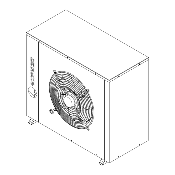
- Page 24 AU12 Installation Manual and Technical Service 2.2. Dimensions and connections The overall dimensions and hydraulic connections of A12 units are listed below. 1000 1000 Figure 2.1.Overall dimensions and hydraulic connections (Amounts in mm). Description Description Male fluid outlet G1-1/4” Cable grommet Male fluid intake G1-1/4”...
- Page 25 AU12 Installation Manual and Technical Service 2.3. Unpacking To unpack the heat pump, remove the wooden box carefully, remove the pallet anchoring screws and check that the heat pump has not been damaged during transportation. Anchoring studs to the pallet Figure 2.2.Disassembly of the transport fastening systems.
- Page 26 AU12 Installation Manual and Technical Service Installing 1 AU12 unit >200 >300 >300 >1200 Figure 2.3. Minimum recommended service areas around the AU12 unit (expressed in mm). Installing 2 or more AU12 units >200 >200 >500 >300 >300 >1200 >1200 Figure 2.4.
- Page 27 AU12 Installation Manual and Technical Service If the unit is installed on a surface that does not drain, place a pipe to channel the defrost water from the unit outlet to the nearest drain. Figures 2.5 and 2.6 show several proposed systems to evacuate the water, depending on the support system.
- Page 28 AU12 Installation Manual and Technical Service Floor-mounting with drainage Figure 2.6. Support system with tray connected to a layer of gravel to drain the water. 3. Hydraulic installation The installation drawings included from here on should be considered simply as a guide. ...
- Page 29 AU12 Installation Manual and Technical Service 3.2. Brine circuit The geothermal heat pumps of the ecoGEO Basic and ecoGEO Compact range can operate with outdoor air as the only heat source, replacing the geothermal collector with one (A) or more AU12 aerothermal units (B). They can also operate as a hybrid system that uses outdoor air and the earth as heat sources by combining one or more AU12 units with a geothermal collector (C).
- Page 30 The heat pump control panel is fully capable of managing all the diagrams represented in Figure 3.1. 4.1. Electrical panel of the ecoGEO AU12 unit. An exploded view of the electrical connections panel of the ecoGEO AU12 unit is shown below. Figure 4.1. Electrical panel of the AU12 unit.
- Page 31 AU12 Installation Manual and Technical Service Use a T20 Torx screwdriver to open the screws numbered "4" on the electrical panel. Make sure the cables are properly fastened to the connections of the electrical panel and none of the wires lies outside. NOTE ...
- Page 32 AU12 Installation Manual and Technical Service 4.2. Electrical connections for aerothermal brine (Diagrams A and B) If the brine system is purely aerothermal and only uses AU12 units (See Diagrams A and B in Figure 3.1), the following electrical connections should be made: ecoGEO B/C AU12 Loff...
- Page 33 AU12 Installation Manual and Technical Service 4.4. Wiring dimensions Table 4.4 shows all the information needed to calculate the necessary number of cables and their sizes. This specific section is a guide, since the wiring must be calculated according to the electrical code of the region where the equipment is installed. Remember that the various signals do not interfere with each other, so all the cables can be placed together, even inside the same cable hose.
- Page 34 AU12 Installation Manual and Technical Service Aerothermal source Aerothermal collector Fan: 1. Used to adjust the maximum and minimum fan speed percentage allowed. The recommended minimum is 40% and the recommended maximum is 70%. DTair unit : 4.0C ASFnominal: 0.45 2.
- Page 35 AU12 Installation Manual and Technical Service Air Unit Hybrid / Heat Unit System Tin: In hybrid brine systems (geothermal-aerothermal), it displays the inlet and return Tout: temperatures and the percentage of energy absorption in each brine system. It also %Fan: ASF: displays the air-antifreeze temperature difference, the aerothermal operating factor and DT Ait Unit:...
- Page 36 AU12 Installation Manual and Technical Service 7. Maintenance The maintenance tasks for the AU12 aerothermal unit and the aerothermal and hybrid brine systems must be carried out by qualified personnel equipped with all the necessary safety material. Before performing any operation on the unit, disconnect the power supply. ...
- Page 37 8.1. Manufacturer's warranty ECOFOREST is liable for lack of conformity of the product or its spare parts, in compliance with the current regulations of the country where the product is purchased. The warranty is only valid in the country where the product is purchased.
- Page 38 In order for this warranty to be considered valid the following conditions must be verified. ECOFOREST must allow the product under warranty to be sold in the country where it is going to be installed. The product under warranty must be used exclusively for the purpose that it was designed for.
- Page 39 Allgemeine Anweisungen .............................. 46 3.2. Solekreis ..................................47 4. Elektroinstallation ................................. 48 4.1. Anschlusskasten der Einheit ecoGEO AU12........................48 4.2. Elektrische Anschlüsse für aerothermische Aufnahme (Schema A und B) ............... 50 4.3. Elektrische Anschlüsse für geothermische-aerothermische-Hybriderfassung (Schema C) ..........50 4.4.
- Page 40 Installations- und technische Wartungsanleitung AU12 1. Allgemeine Informationen Diese Anleitung enthält die notwendigen Informationen für die Installation, Inbetriebnahme und Wartung der aerothermischen Einheiten AU12 für die Wärmepumpen der Baureihe Basic und Compact. Sie enthält auch hilfreiche Informationen für den Endbenutzer. Es wird empfohlen, vor allen Arbeiten am Gerät diese Anleitung aufmerksam durchzulesen. Bewahren Sie diese Anleitung für die Einsichtnahme in der Zukunft auf.
- Page 41 Installations- und technische Wartungsanleitung AU12 Hydraulische Installation Die Installation und nachfolgende Maßnahmen an den Wasserkreisläufen dürfen nur von einem autorisierten Fachmann und unter Einhaltung der anwendbaren örtlichen Bestimmungen und der in dieser Anleitung enthaltenen Anweisungen ausgeführt werden. Während oder sofort nach dem Betrieb der Anlage nicht die Leitungen berühren, da durch Hitze oder Kälte Verletzungen verursacht werden können.
- Page 42 Installations- und technische Wartungsanleitung AU12 2.2. Abmessungen und Anschlüsse Nachfolgenden werden die allgemeinen Abmessungen und die hydraulischen Anschlüsse der Geräte AU12 angegeben. 1000 1000 Abb. 2.1. Allgemeine Abmessungen und hydraulische Anschlüsse (Angabe in mm). Beschreibung Beschreibung Flüssigkeitsauslass G1-1/4” Außengewinde Kabeldurchführung Flüssigkeitseinlass G1-1/4”...
- Page 43 Installations- und technische Wartungsanleitung AU12 2.3. Auspacken Zum Auspacken der Einheit AU12 die Holzkiste vorsichtig entfernen, die Befestigungsschrauben an der Palette vorsichtig herausdrehen und sicherstellen, dass das Gerät auf dem Transport nicht beschädigt worden ist. Verankerungen an der Palette Abb. 2.2. Entfernen der Befestigungsvorrichtungen für den Transport. 2.4.
- Page 44 Installations- und technische Wartungsanleitung AU12 2.5. Wartungsbereiche Nachfolgend werden die empfohlenen Mindestabstände um die Einheit AU12 herum angegeben, um die Arbeiten zur Installation, Inbetriebnahme und Wartung zu ermöglichen. Installation von 1 Einheit AU12 >200 >300 >300 >1200 Abb. 2.3. Empfohlene Mindestfreiräume um die Einheit AU12 (Angabe in mm). Installation von 2 oder mehr Einheiten AU12 >200 >200...
- Page 45 Installations- und technische Wartungsanleitung AU12 Sicherstellen, dass dieses Wasser nicht auf Flächen ohne Dränage läuft, wie z. B. asphaltierte Flächen oder mit Fliesen usw. Dieses Wasser könnte bei tiefen Temperaturen gefrieren und eine Ausrutschgefahr darstellen. Wenn das Gerät auf Flächen ohne Dränage installiert wird, muss eine Leitung zum Ableiten des Wassers aus der Abtauung vom Ablauf des Geräts zum nächstgelegenen Ablauf installiert werden.
- Page 46 Installations- und technische Wartungsanleitung AU12 Bodenmontage mit Dränage Abb. 2.6. Trägersystem mit Auffangwanne, die zum Wasserablauf mit der Kiesschicht verbunden ist. 3. Hydraulische Installation Die hierin enthaltenen Installationspläne dienen nur als Beispiel. Die Bemessung der hydraulischen Anlage muss von einem Fachmann und gemäß den HINWEIS anwendbaren Vorschriften vor Ort vorgenommen werden.
- Page 47 Installations- und technische Wartungsanleitung AU12 3.2. Solekreis Die Erdwärmepumpen der Baureihe ecoGEO Basic und ecoGEO Compact können mit Außenluft als einzige Wärmequelle betrieben werden, wobei der geothermische Aufnehmer durch eine (A) oder mehrere (B) aerothermische Einheiten AU12 ersetzt wird. Sie können auch als Hybridsystem mit der Außenluft und dem Boden als Wärmequelle durch Kombination einer oder mehrerer Einheiten AU12 mit einem geothermischen Aufnehmer (C) betrieben werden.
- Page 48 Wärmepumpen ecoGEO aus durchgeführt werden. Die Steuerung der Wärmepumpe ist in der Lage, alle Schemata der Abb. 3.1 komplett zu steuern. 4.1. Anschlusskasten der Einheit ecoGEO AU12. Es folgt eine Explosionszeichnung des elektrischen Anschlusskastens der Einheit ecoGEO AU12. Abb. 4.1. Stromkasten der Einheit AU12. Beschreibung Beschreibung Elektrische Steueranschlüsse...
- Page 49 Installations- und technische Wartungsanleitung AU12 Mit einem Torx-Schraubendreher der Größe T20 den Anschlusskasten an den mit Nr. 4 bezeichneten Schrauben öffnen. Sicherstellen, dass die Kabel an den Anschlüssen des Anschlusskastens korrekt angeschlossen sind und kein Leiter vergessen wird. HINWEIS ...
- Page 50 Installations- und technische Wartungsanleitung AU12 4.2. Elektrische Anschlüsse für aerothermische Aufnahme (Schema A und B) Wenn zur Energieaufnahme nur die Aerothermie unter Verwendung der Einheiten AU12 verwendet wird (siehe Schema A und B der Abb. 3.1), müssen die folgenden elektrischen Anschlüsse hergestellt werden: ecoGEO B/C AU12 Loff...
- Page 51 Installations- und technische Wartungsanleitung AU12 4.4. Kabelauslegung Die Tabelle 4.4 enthält alle erforderlichen Informationen zur Berechnung der Anzahl der Kabel und ihres Querschnitts. Die Querschnittsangabe ist rein informativ. Der Querschnitt muss auf Grundlage der Elektroverordnung des Gebiets berechnet werden, wo die Geräte installiert werden. Es ist zu berücksichtigen, dass die verschiedenen Signale untereinander keine Störungen verursachen, weshalb alle Kabel zusammen und sogar in einem Kabelschlauch verlegt werden können.
- Page 52 Installations- und technische Wartungsanleitung AU12 AeheicheQee Aerothermisches System Mi Mx Vei: 1. Der max. und min. zulässige Prozentsatz der Lüftergeschwindigkeit kann eingestellt werden. Es wird empfohlen, einen Mindestwert von 40 % und einen Höchstwert von Tfeihei: 4.0 ASi: 0.45 70 % einzustellen. 2.
- Page 53 Installations- und technische Wartungsanleitung AU12 ezee P fi Ae AiUi Hybridsystem / Luftheizung Ti: 12.3 Bei hybriden Aufnahmesystemen (Geothermie-Aerothermie) werden die Vor- und T: 12.3 Rücklauftemperaturen und der Prozentsatz aufgenommener Energie der einzelnen %: 100% AS: 0.98 Aufnahmesysteme angezeigt. Ebenso wird Temperaturunterschied Luft-...
- Page 54 Installations- und technische Wartungsanleitung AU12 Das Abtauen erfolgt durch einen integrierten Wärmetauscher in der Wärmepumpe ecoGEO und bei stehendem Kompressor. Zur Verwendung des Frostschutzmittels immer die geltenden Bestimmungen vor Ort beachten. Die Frostschutztemperatur an die Art der Installation anpassen und die entsprechenden Schutzelemente konfigurieren. Das Gemisch aus Frostschutzmittel und Wasser im richtigen Verhältnis herstellen, um die erforderliche Gefriertemperatur zu erhalten.
- Page 55 Installations- und technische Wartungsanleitung AU12 Sicherstellen, dass das Signal 0-10 V DC zur Steuerung der Lüftergeschwindigkeit korrekt ist. Sicherstellen, dass der Temperaturfühler am Auslass der Einheit AU12 einen richtigen Wert misst. 7.1. Anbringen und Entfernen der oberen Abdeckung Zum Anbringen und Entfernen der Abdeckungen ist ein 4 mm Innensechskantschlüssel erforderlich.
- Page 56 Vorschriften im Land, wo das Produkt verkauft wurde. Diese Garantie gilt nur in dem Land, wo der Verkauf des Produkts erfolgte. Mit vorheriger Zustimmung von ECOFOREST kann Ihnen Ihr Vertragshändler vor Ort eine Erweiterung der Garantie anbieten, die in den gesetzlichen Vorschriften gefordert sein kann.
- Page 57 3.2. Circuit de captage ................................. 65 4. Installation électrique ................................66 4.1. Boîtier électrique de l'unité ecoGEO AU12........................66 4.2. Branchements électriques du système de captage aérothermique (schémas A et B)............68 4.3. Branchements électriques d'un système de captage hybride géothermique-aérothermique (schéma C) ......68 4.4.
- Page 58 Manuel d'installation et de service technique AU12 1. Généralités Ce manuel contient les informations nécessaires à l'installation, à la mise en marche et à la maintenance des unités de captage aérothermique AU12 conçues pour la gamme de pompes à chaleur ecoGEO Basic et Compact. Ce document fournit également des informations utiles pour l'utilisateur final.
- Page 59 Manuel d'installation et de service technique AU12 Installation hydraulique L'installation et les interventions ultérieures sur les circuits hydrauliques doivent uniquement être exécutées par un technicien agréé dans le respect des règlements locaux applicables et des instructions figurant dans ce manuel. ...
- Page 60 Manuel d'installation et de service technique AU12 2.2. Dimensions et raccords Les dimensions générales et les raccords hydrauliques des unités A12 sont illustrés sur les figures ci-dessous : 1000 1000 Figure 2.1. Dimensions générales et raccords hydrauliques (cotes en mm). Description Description Sortie de fluide G1-1/4”...
- Page 61 Manuel d'installation et de service technique AU12 2.3. Déballage Pour déballer l'unité AU12, retirer soigneusement la caisse en bois, enlever les vis de fixation à la palette et s'assurer que l'équipement ne s'est pas endommagé pendant le transport. Ancrages à la palette Figure 2.2.
- Page 62 Manuel d'installation et de service technique AU12 2.5. Distances d'intervention Les distances minimales recommandées autour de l'unité AU12 pour garantir son bon fonctionnement et faciliter les opérations d'installation, de mise en marche et de maintenance sont illustrées sur les figures ci-dessous : Installation d'une unité...
- Page 63 Manuel d'installation et de service technique AU12 Veiller à ce que cette eau ne se répande pas sur des surfaces impossibles à drainer (surfaces goudronnées, carrelées, etc.). Cette eau peut en effet geler sous l'effet de basses températures et exposer les personnes à un risque de glissade. ...
- Page 64 Manuel d'installation et de service technique AU12 Montage sur sol avec couche de drainage Figure 2.6. Support avec raccordement du bac à la couche de gravier utilisée pour le drainage de l'eau 3. Installation hydraulique Les schémas d'installation illustrés dans les pages qui suivent sont fournis à titre indicatif. ...
- Page 65 Manuel d'installation et de service technique AU12 3.2. Circuit de captage Les pompes à chaleur géothermiques de la gamme ecoGEO Basic et ecoGEO Compact peuvent fonctionner en utilisant l'air extérieur comme seule et unique source de chaleur en remplaçant le capteur géothermique par une (A) ou plusieurs unités aérothermiques AU12 (B).
- Page 66 électrique des pompes à chaleur ecoGEO. La commande de la pompe à chaleur est capable de gérer entièrement tous les schémas de la figure 3.1. 4.1. Boîtier électrique de l'unité ecoGEO AU12 Le boîtier de raccordements électriques de l'unité ecoGEO AU12 est représenté ci-dessous : Figure 4.1. Boîtier électrique de l'unité AU12 Description Description Branchements électriques de commande...
- Page 67 Manuel d'installation et de service technique AU12 Utiliser un tournevis Torx T20 pour desserrer les vis (numéro 4 sur l'illustration) et ouvrir le boîtier électrique. Veiller à ce que tous les fils des câbles soient parfaitement introduits dans les orifices de branchement du boîtier électrique.
- Page 68 Manuel d'installation et de service technique AU12 4.2. Branchements électriques du système de captage aérothermique (schémas A et B) Si le système de captage est purement aérothermique et que seuls des unités AU12 sont utilisées (cf. schémas A et B de la figure 3.1), les branchements électriques à...
- Page 69 Manuel d'installation et de service technique AU12 4.4. Dimensionnement du câblage Le tableau 4.4 contient toutes les informations nécessaires au calcul du nombre de câbles et de leur section. La section spécifiée est fournie à titre indicatif et doit être calculée conformément à la réglementation électrique de la région dans laquelle les équipements sont installés.
- Page 70 Manuel d'installation et de service technique AU12 Captage erothermique Capteur aérothermique Ventilateur: 1. Ce sous-menu permet de régler la valeur maximale et la valeur minimale du pourcentage de vitesse du ventilateur autorisé. Il est recommandé de régler la valeur DTaerotherme: 4.0C ASFnominal: 0.45...
- Page 71 Manuel d'installation et de service technique AU12 Air Unit Système hybride/Aérotherme Tin: 14.7C Sur un système de captage hybride (système géothermique et système aérothermique), Tout: 14.7C cet écran affiche les températures de départ et de retour ainsi que le pourcentage %Fan: 100% ASF:...
- Page 72 Manuel d'installation et de service technique AU12 7. Maintenance Les opérations de maintenance de l'unité aérothermique AU12 ainsi que des systèmes de captage aérothermique et hybrides doivent être réalisées par du personnel qualifié équipé de tout le matériel de sécurité approprié. ...
- Page 73 8.1. Garantie du fabricant La société ECOFOREST est tenue responsable des défauts de conformité détectés sur les produits ou leurs pièces de rechange en accord avec la réglementation en vigueur dans le pays au sein duquel la vente s'est déroulée. Cette garantie n'est valable qu'au sein du pays où...
- Page 74 Tous les travaux d'installation, de mise en marche, de maintenance et de réparation de l'équipement doivent être exécutés par un service technique agréé par ECOFOREST. Tout remplacement de pièces doit être mené à bien par un service technique agréé par ECOFOREST, ce dernier devant systématiquement utiliser des pièces d'origine ECOFOREST.
- Page 75 3.2. Aanvoercircuit ................................83 4. Elektrische installatie ................................84 4.1. Elektriceitskast van de ecoGEO AU12 unit........................84 4.2. Elektrische aansluitingen voor aerothermische aanvoer (Schema's A en B) ..............86 4.3. Elektrische aansluitingen voor hybride geothermische-aerothermische aanvoer (Schema's C) ........86 4.4.
- Page 76 Handleiding installatie en servicedienst AU12 1. Algemene informatie Deze handleiding bevat de nodige informatie voor de installatie, inbedrijfstelling en onderhoud van de aerothermische aanvoerunits AU12 voor het gamma warmtepompen ecoGEO Basic en Compact. U treft ook nuttige informatie voor de eindgebruiker aan.
- Page 77 Handleiding installatie en servicedienst AU12 Hydraulische installatie De installatie en de daaropvolgende werkzaamheden aan de hydraulische circuits mogen uitsluitend worden uitgevoerd door bevoegd personeel in overeenstemming met de geldende lokale voorschriften en de instructies in deze handleiding. Raak de leidingen tijdens of onmiddellijk na gebruik van de warmtepomp niet aan. Ze kunnen bij aanraking brandwonden door hitte of kou veroorzaken.
- Page 78 Handleiding installatie en servicedienst AU12 2.2. Afmetingen en aansluitingen Hierna worden de algemene afmetingen en hydraulische aansluitingen van de A12 units aangeduid. 1000 1000 Figuur 2.1. Algemene afmetingen en hydraulische aansluitingen (maten in mm). Beschrijving Beschrijving Vloeistofuitlaat G1-1/4” Stift Kabeldoorvoer Vloeistofinlaat G1-1/4”...
- Page 79 Handleiding installatie en servicedienst AU12 2.3. Uitpakken Verwijder, om de unit uit te pakken, voorzichtig de houten doos, de schroeven voor bevestiging aan de pallet en controleer dat de unit tijdens het transport niet beschadigd werd. Verankeringen aan de pallet Figuur 2.2.
- Page 80 Handleiding installatie en servicedienst AU12 Installatie van 1 AU12 unit >200 >300 >300 >1200 Figuur 2.3. Aanbevolen minimumservicezones rond de AU12 unit (maten in mm). Installatie van 2 of meer AU12 units >200 >200 >500 >300 >300 >1200 >1200 Figuur 2.4. Aanbevolen minimumservicezones rond de AU12 unit (maten in mm). 2.6.
- Page 81 Handleiding installatie en servicedienst AU12 Indien u de unit installeert op niet-drainerende oppervlakken, installeer dan een leiding om het water afkomstig van de ontijzing te leiden van de afvoer van het apparaat naar de dichtstbijzijnde afvoer. In de Figuren 2.5 en 2.6 worden enkele voorgestelde systemen getoond om dit water te evacueren, afhankelijk van het ondersteuningssysteem.
- Page 82 Handleiding installatie en servicedienst AU12 Montage op de vloer met afvoer Figuur 2.6. Ondersteuningssysteem met plaat aangesloten op grindlaag voor de afwatering. 3. Hydraulische installatie De hierna opgenomen installatieschema's zijn enkel indicatieve schema's. Het ontwerp van de hydraulische installatie moet worden uitgevoerd door gespecialiseerd OPMERKING personeel in overeenstemming met de toepasbare lokale voorschriften.
- Page 83 Handleiding installatie en servicedienst AU12 3.2. Aanvoercircuit De geothermische warmtepompen van het gamma ecoGEO Basic en ecoGEO Compact kunnen werken met buitenlucht als enige warmtebron, waarbij de geothermische sensor vervangen wordt door een (A) of verschillende aerothermische units AU12 (B). Deze kunnen ook werken door het hybridiseren van de buitenlucht en het terrein als warmtebronnen gecombineerd met een of verschillende AU12 units met een geothermische sensor (C).
- Page 84 Via de bediening van de warmtepomp kunnen alle schema's van Figuur 3.1 beheerd worden. 4.1. Elektriceitskast van de ecoGEO AU12 unit. Hierna wordt een opengewerkte tekening weergegeven van de elektrische aansluitingenkast van de ecoGEO AU12 unit. Figuur 4.1. Elektriceitskast van de AU12 unit.
- Page 85 Handleiding installatie en servicedienst AU12 Gebruik een torxschroevendraaier met maat T20 om de elektriciteitskast te openen aan de met nummer 4 aangeduide bouten. Zorg dat de kabels goed aangesloten zijn op de aansluitingen van de elektrische kast en dat geen draden buiten hangen.
- Page 86 Handleiding installatie en servicedienst AU12 4.2. Elektrische aansluitingen voor aerothermische aanvoer (Schema's A en B) Indien het aanvoersysteem volledig aerothermisch is aan de hand van enkel AU12 units (zie schema's A en B van de Figuur 3.1) moeten onderstaande elektrische aansluitingen worden uitgevoerd: ecoGEO B/C AU12 Loff...
- Page 87 Handleiding installatie en servicedienst AU12 4.4. Dimensionering van de bedrading In Tabel 4.4 treft u alle informatie aan die vereist is voor het berekenen van het kabelnummer en de doorsnede. De aangeduide doorsnede is ter informatie en moet worden berekend volgens de elektrische voorschriften van het gebied waar de apparaten geïnstalleerd worden.
- Page 88 Handleiding installatie en servicedienst AU12 Aerothermal source Aerothermische sensor Fan: 40 70% 1. Voor het afstellen van het maximaal en minimaal toegelaten percentage van ventilatorsnelheid. Het is raadzaam het minimum in te stellen op 40% en het DTair unit : 4.0C ASFnominal: 0.45...
- Page 89 Handleiding installatie en servicedienst AU12 Gebruikers Menu Zwembad Informatie Alarmen Air Unit Hybride systeem/Luchtverhitter Tin: 14.7C In hybride aanvoersystemen (geotermische-aerotermische) worden de aanvoer- en Tout: 14.7C retourtemperaturen, het opnamepercentage van energie in elk van de aanvoersystemen %Fan: 100% ASF: 0.89 weergegeven.
- Page 90 Handleiding installatie en servicedienst AU12 De ontijzing wordt uitgevoerd aan de hand van een warmtewisselaar die geïntegreerd is in de ecoGEO warmtepomp met stopgezette compressor. Raadpleeg altijd de lokale voorschriften voordat u antivriesmiddel gebruikt. Pas de vriestemperatuur aan het installatietype aan en configureer de overeenstemmende beveiligingen. Voer het water- antivriesmengsel uit in de geschikte verhouding voor de vereiste vriestemperatuur.
- Page 91 Handleiding installatie en servicedienst AU12 Controleer het elektrische verbruik van de ventilator bij maximale snelheid. Controleer dat het signaal 0-10Vdc voor de snelheidscontrole van de ventilator correct is. Controleer dat de temperatuursensor aan de uitlaat van de AU12 units een correcte waarde meet. 7.1.
- Page 92 8. Garantie en servicedienst 8.1. Garantie van de fabrikant ECOFOREST is aansprakelijk voor tekortkomingen die opduiken aan het product of de onderdelen volgens de geldende wetgeving van het land van de aankoop. Deze garantie is enkel geldig in het land van aankoop.
- Page 93 3.2. Circuito di captazione ..............................101 4. Impianto elettrico ................................102 4.1. Quadro elettrico dell'unità ecoGEO AU12........................102 4.2. Collegamenti elettrici per captazione aerotermica (schemi A e B) ................104 4.3. Collegamenti elettrici per captazione ibrida geotermica-aerotermica (schema C) ............104 4.4.
- Page 94 Manuale di installazione e assistenza tecnica AU12 1. Informazioni generali Il presente manuale contiene le informazioni necessarie per l'installazione, la messa in servizio e la manutenzione di unità di captazione aerotermiche AU12 per la gamma di pompe di calore ecoGEO Basic e Compact. Si possono anche trovare informazioni utili per l'utente finale.
- Page 95 Manuale di installazione e assistenza tecnica AU12 Impianto idraulico L'installazione e le successive manipolazioni sui circuiti idraulici devono essere effettuate esclusivamente da un tecnico autorizzato seguendo le normative locali applicabili e le istruzioni raccolte nel presente manuale. Non toccare i tubi, durante o subito dopo il funzionamento dell'apparecchiatura, dal momento che potrebbero causare bruciature provocate dal calore o dal freddo.
- Page 96 Manuale di installazione e assistenza tecnica AU12 2.2. Dimensioni e collegamenti A seguire verranno descritte le dimensioni generali e i collegamenti idraulici delle unità A12. 1000 1000 Figura 2.1. Dimensioni generali e collegamenti idraulici (quote in mm). Nº Descrizione Nº Descrizione Uscita fluido G1-1/4”...
- Page 97 Manuale di installazione e assistenza tecnica AU12 2.3. Smontaggio Per smontare l'unità AU12 rimuovere accuratamente la cassetta di legno, le viti di ancoraggio al pallet e verificare che l'unità non si è danneggiata durante il trasporto. Ancoraggi al pallet Figura 2.2. Smontaggio dei sistemi di fissaggio per il trasporto. 2.4.
- Page 98 Manuale di installazione e assistenza tecnica AU12 Installazione 1 unità AU12 >200 >300 >300 >1200 Figura 2.3. Aree di assistenza minime consigliate intorno all'unità AU12 (quote in mm). Installazione di 2 o più unità AU12 >200 >200 >500 >300 >300 >1200 >1200 Figura 2.4.
- Page 99 Manuale di installazione e assistenza tecnica AU12 Se l'unità viene installata su superfici non drenanti, installare un tubo per far convogliare l'acqua prodotta dallo sbrinamento dallo scarico dell'apparecchiatura allo scarico più vicino. Nelle Figure 2.5 e 2.6 vengono illustrati alcuni dei sistemi proposti per scaricare quest'acqua in funzione del sistema di supporto.
- Page 100 Manuale di installazione e assistenza tecnica AU12 Montaggio al pavimento con scarico Figura 2.6. Sistema supporto con vassoio collegato a strato di ghiaia per lo scarico dell'acqua. 3. Impianto idraulico Gli schemi di installazione inseriti più avanti sono solo orientativi. ...
- Page 101 Manuale di installazione e assistenza tecnica AU12 3.2. Circuito di captazione Le pompe di calore geotermiche della gamma ecoGEO Basic e ecoGEO Compact possono funzionare con aria esterna come unica fonte di calore, sostituendo il rilevatore geotermico da una (A) o varie unità aerotermiche AU12 (B). Possono anche funzionare eseguendo l'ibridazione dell'aria esterna e del terreno come fonti di calore combinando una o varie unità...
- Page 102 Il controllo della pompa di calore è capace di gestire completamente tutti gli schemi della Figura 3.1. 4.1. Quadro elettrico dell'unità ecoGEO AU12. A seguire viene illustrata l'interruzione della scatola dei collegamenti elettrici dell'unità ecoGEO AU12. Figura 4.1. Quadro elettrico dell'unità AU12.
- Page 103 Manuale di installazione e assistenza tecnica AU12 Utilizzare un cacciavite torx di misura T20 per aprire il quadro elettrico partendo dalle viti indicate con il numero 4. Assicurarsi che i cavi siano ben collegati ai collegamenti del quadro elettrico senza che nessun filo rimanga da fuori.
- Page 104 Manuale di installazione e assistenza tecnica AU12 4.2. Collegamenti elettrici per captazione aerotermica (schemi A e B) Se il sistema di captazione è puramente aerotermico utilizzando solo unità AU12 (vedere schemi A e B della Figura 3.1) si devono effettuare i seguenti collegamenti elettrici: ecoGEO B/C AU12 Loff...
- Page 105 Manuale di installazione e assistenza tecnica AU12 4.4. Dimensionamento del cablaggio Nella Tabella 4.4 è possibile trovare tutte le informazioni necessarie per calcolare il numero di cavi e la loro sezione. La sezione specificata è orientativa dovendo essere calcolata seguendo la normativa elettrica della regione nella quale si installano le apparecchiature.
- Page 106 Manuale di installazione e assistenza tecnica AU12 Czeeemc Rilevatore aerotermico Vee: 40 70% 1. Consente di regolare la percentuale di velocità minima e massima consentita del ventilatore. Si consiglia di regolare un minimo del 40% e un massimo del 70%. DTeem: 4.0C ASFme:...
- Page 107 Manuale di installazione e assistenza tecnica AU12 AU Sistema ibrido / Aerotermo T: 14.7C Nei sistemi di captazione ibridi (geotermico-aerotermico) mostra le temperature di T: 14.7C andata e ritorno, la percentuale di assorbimento di energia in ciascuno dei sistemi di %F: 100% ASF:...
- Page 108 Manuale di installazione e assistenza tecnica AU12 7. Manutenzione Le operazioni di manutenzione dell'unità aerotermica AU12, così come dei sistemi di captazione aerotermici e ibridi, devono essere effettuate da personale qualificato provvisto di tutti i materiali di sicurezza adatti. Prima di effettuare qualsiasi operazione nell'unità, scollegare l'alimentazione elettrica.
- Page 109 8.1. Garanzia del produttore ECOFOREST è responsabile per il mancato rispetto delle normative del prodotto o dei pezzi di ricambio secondo la normativa vigente nel paese in cui si effettua la compravendita. Questa garanzia è valida esclusivamente all'interno del paese in cui si effettua la compravendita.
- Page 110 8.2. Distributori e assistenza tecnica autorizzati ECOFOREST dispone di un'ampia rete composta da aziende autorizzate per la distribuzione e l'assistenza tecnica dei prodotti. Questa rete vi fornirà le informazioni e l'assistenza tecnica necessaria per qualsiasi situazione e in qualsiasi luogo.
- Page 112 ECOFOREST GEOTERMIA, S.L. Poligono industrial A pasaxe C/15 - nº22 - parcela 139 36316 - Vincios / Gondomar - Pontevedra (Spain) Tel.: +34 986 262 184 / +34 986 417 700 Fax: +34 986 262 186 e-mail: Info@ecoforest.es http://www.ecoforest.es The manufacturer reserves the right to make any necessary changes to the contents of this manual without prior notice.
Need help?
Do you have a question about the ecoGEO AU12 and is the answer not in the manual?
Questions and answers