
Related Manuals for RTI SiloKing 1100 LS


Summary of Contents for RTI SiloKing 1100 LS
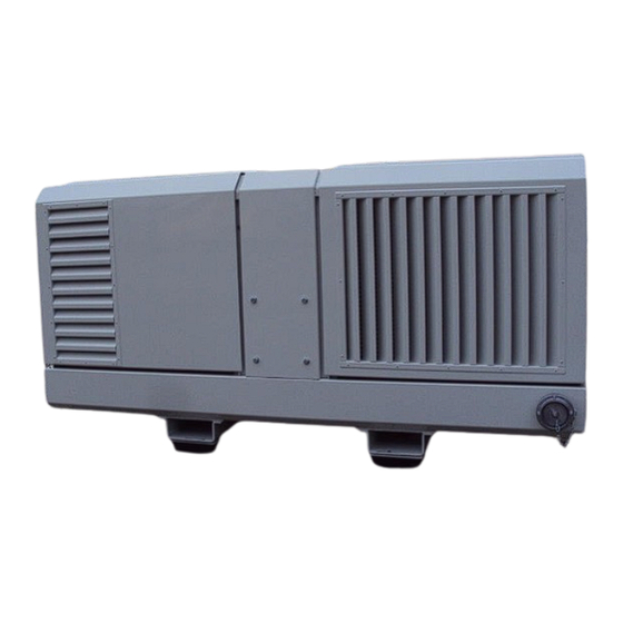
- Page 1 INSTRUCTION AND OPERATING MANUAL RTI Compressor unit w ith electric motor SiloKing 1100 LS (These pictures are only examples)
- Page 2 Preface Carefully read these instructions and the compressor instruction before setting up and going into operation. These manuals contain essential information that must be read to ensure interference-free operation and to achieve longevity. Repairs, maintenance or conversion work shall only be carried out by authorised, trained and qualified personnel that are familiar with the current safety regulations.
-
Page 3: Table Of Contents
Contents General Purpose Contact details Identification Service contacts Technical data – compressor unit w ith electrical motor Installation procedure Electrical connection Safety General Qualification and training personnel Operating safety conscious Safety instructions operator Modifications and repairing spare parts Modifications unit Commissioning Set-up Operating elements and monitoring gauges... -
Page 4: General
1 General Purpose RTI builds and supplies the compressor unit with electric motor ready for operation. These units are used to handle bulk material pneumatically due to their ability to compress atmospheric air free of oil. They can either be installed as a stationary unit or mounted on silo-type trucks. - Page 5 Technical data – compressor unit with motor CVS SiloKing 1100 LS w ith 55/75 kW electrical motor Technical data compressor Manufacturer Type SiloKing1100LS System Screw Quantity Volume flow 980 m³/h at 2 bar and 2930 rpm Suction conditions 1 Bar -20° C...
-
Page 6: Installation Procedure
Important!! The compressor unit is equipped with additional oil cooler therefore, after an oil change, the oil level may vary from the oil quantity specified in the operating instructions. Important!! The function of the non-return valve installed in the compressor unit is to prevent the compressor, after having been switched off, from running in reverse at high speed for a long time as a result of residual pressure that exists in the discharge lines of the pneumatic system. -
Page 7: Electrical Connection
Electrical connection Phase Neut r al Important !! Any work on the compressor such as operation and maintenance shall only be carried out by authorised, skilled and qualified personnel, who are familiar with the applicable safety regulations. -
Page 8: Safety
Using foreign spare parts and accessories may entail the loss of any liability for the consequences arising therefrom. 2.6 Modifications installation Without approval from RTI, it is not permitted to make any alterations to the installation. -
Page 9: Commissioning
Commissioning Set-up Mount the compressor unit in horizontal position, if possible. If the unit is not mounted horizontally, please observe the specified limit values. Important!! Maximum permissible angles of tilt during operation: forward and backward: 10° to the right and left: 10° Operating elements and monitoring gauges ... -
Page 10: Monitoring Compressor Operation
Monitoring compressor operation Oil pressure gauge The oil pressure is indicated on the oil pressure gauge. The oil pressure must not fall below 0.3 bar. Important!! If the oil pressure does not build up within a short period of time, switch of the motor / compressor. -
Page 11: Maintenance/Service
Maintenance/Service Maintenance intervals Important!! In case of compressor units with V-belt drive, re-tension the V-belts and the quick-lock taper bushes of the V-belt pulleys and the fastening screws of the discharge silencer after the first two hours of operation. INSPECTION DURING OPERATION: The oil pressure must not drop below the minimum value of 0.3 bar, (normally 1-3 bar). - Page 12 MONTHLY INSPECTION: ONLY CARRY OUT WHEN INSTALLATION IS COOL AND AT A STANDSTILL WITH THE POWER CORD DISCONNECTED OR THE MAIN SWITCH OFF This check may only be carried out by skilled mechanics. Observe the safety very carefully, the enclosure must be removed and rotating parts will be accessible. Check the wear of the V-belts, replace if necessary.
-
Page 13: V-Belt Drive
Important!! Prior to conducting any work on the compressor unit with motor, make sure that the main switch is set to position “0“ and that the main power cable is disconnected and that the power is off. Prior to opening the sound cover, remove the safety locks and open the sound cover only when the compressor is at standstill. -
Page 14: Malfunctions And Remedies Compressor
Malfunctions and remedies compressor Malfunction Possible cause Remedy Oil pressure below 0.3 bar Drive speed to low Check drive speed at operating temperature Oil filter soiled Clean oil strainer Oil level to low Top up oil Oil pressure varies Oil level to low Top up oil Oil intake pipe leaking Check screw ed connection...
Need help?
Do you have a question about the SiloKing 1100 LS and is the answer not in the manual?
Questions and answers