Table of Contents
Advertisement
Notes: This model's DVD/CD mechanism changer unit is CR14. Please refer to the original service manual
(Order No. MD0801004CE) for this mechanism.
Specifications
AMPLIFIER SECTION
RMS Output Power Stereo mode:
Front Ch
125 W per channel (3 Ω), 1 kHz, 10% THD
Total RMS Stereo mode power
PMPO output power
FM/AM TUNER, TERMINALS SECTION
Preset station
Frequency Modulation (FM)
Frequency range
Antenna terminals
Amplitude Modulation (AM)
Frequency range
Digital audio output
Coaxial digital output
Music Port (Front)
Terminal
250 W
2800 W
FM 30 stations
AM 15 stations
87.50 to 108.00 MHz (50 kHz
step)
75 Ω (unbalanced)
522 to 1629 kHz (9 kHz step)
Pin jack
Stereo, 3.5 mm jack
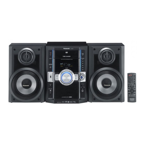
DVD Stereo System
SA-VK470EE
Colour
(K).......................Black Type
Phone jack
Terminal
Mic jack
Terminal
AUX
Terminal
CASSETTE DECK SECTION
Type
Track system
Heads
Record/playback
Erasure
Motor
Recording system
Erasing system
Tape speed
Overall frequency response (+3, -6 dB) at DECK OUT
Normal
© 2008 Matsushita Electric Industrial Co. Ltd.. All
rights
reserved.
distribution is a violation of law.
ORDER NO. MD0805014CE
Stereo, 3.5 mm jack
Mono, 6.3 mm jack (1 system)
Stereo, RCA jack
Auto reverse
2-Track, 1 Channel
Solid permalloy head
Double gap ferrite head
DC servo motor
AC bias 100 kHz
AC erase 100 kHz
4.8 cm/s
35 Hz to 14 kHz
Unauthorized
copying
and
Advertisement
Table of Contents

Related Manuals for Panasonic SA-VK470EE


Summary of Contents for Panasonic SA-VK470EE
- Page 1 ORDER NO. MD0805014CE DVD Stereo System SA-VK470EE Colour (K).......Black Type Notes: This model’s DVD/CD mechanism changer unit is CR14. Please refer to the original service manual (Order No. MD0801004CE) for this mechanism. Specifications AMPLIFIER SECTION Phone jack RMS Output Power Stereo mode: Terminal Stereo, 3.5 mm jack...
- Page 2 4:0:0, 4:2:0, 4:2:2 or 4:4:4). Extremely long and narrow pictures may not be displayed. MPEG4 data recorded with the Panasonic SD multi cameras or DVD video recorders. Conforming to SD VIDEO specifications (ASF standard)/ MPEG4 (Simple Profile) video system/ G.726 audio system.
- Page 3 SA-VK470EE...
-
Page 4: Table Of Contents
SA-VK470EE CONTENTS Page Page 1 Safety Precautions 9.19. Disassembly of D-Amp P.C.B. 1.1. GENERAL GUIDELINES 9.20. Replacement of Audio Digital Power Amp IC (IC5000) 1.2. Before Repair and Adjustment 9.21. Disassembly of Main P.C.B. 1.3. Protection Circuitry 9.22. Disassembly of SMPS P.C.B. - Page 5 SA-VK470EE 20.2. Main Circuit 21.7. SMPS P.C.B. 20.3. Panel, Side Bar (L) Led, Side Bar (R) Led Circuit 22 Basic Troubleshooting Guide 20.4. Tact Switch, Music Port, Remote Sensor, Mic, USB Circuit 22.1. Troubleshooting Guide for F61 and/or F76 22.2. Basic Troubleshooting Guide for Traverse Unit (DVD 20.5.
-
Page 6: Safety Precautions
SA-VK470EE 1 Safety Precautions 1.1. GENERAL GUIDELINES 1. When servicing, observe the original lead dress. If a short circuit is found, replace all parts which have been overheated or damaged by the short circuit. 2. After servicing, see to it that all the protective devices such as insulation barriers, insulation papers shields are properly installed. -
Page 7: Safety Parts Information
SA-VK470EE “shorted”, or if speaker systems with an impedance less than the indicated rated impedance of the amplifier are used. If this occurs, follow the procedure outlines below: 1. Turn off the power. 2. Determine the cause of the problem and correct it. -
Page 8: Prevention Of Electrostatic Discharge (Esd) To Electrostatically Sensitive (Es) Devices
SA-VK470EE 2 Prevention of Electrostatic Discharge (ESD) to Electrostatically Sensitive (ES) Devices Some semiconductor (solid state) devices can be damaged easily by static electricity. Such components commonly are called Electrostatically Sensitive (ES) Devices. Examples of typical ES devices are integrated circuits and some field-effect transistors and semiconductor “chip”... -
Page 9: Precaution Of Laser Diode
SA-VK470EE 3 Precaution of Laser Diode CAUTION: This product utilizes a laser diode with the unit turned “on”, invisible laser radiation is emitted from the pickup lens. Wavelength: 655 nm (DVD)/785 nm (CD) Maximum output radiation power from pickup: 100 µW/VDE Laser radiation from the pickup unit is safety level, but be sure the followings: 1. -
Page 10: About Lead Free Solder (Pbf)
SA-VK470EE 4 About Lead Free Solder (PbF) 4.1. Service caution based on legal restrictions 4.1.1. General description about Lead Free Solder (PbF) The lead free solder has been used in the mounting process of all electrical components on the printed circuit boards used for this equipment in considering the globally environmental conservation. -
Page 11: Handling Precautions For Traverse Unit
SA-VK470EE 5 Handling Precautions for Traverse Unit The laser diode in the optical pickup unit may break down due to static electricity of clothes or human body. Special care must be taken avoid caution to electrostatic breakdown when servicing and handling the laser diode in the traverse unit. - Page 12 SA-VK470EE...
-
Page 13: Accessories
SA-VK470EE 6 Accessories • • • • Note: Refer to “Replacement Parts List” (Section 25) for the part number. Video cable Remote control FM indoor antenna AC cord AM Loop antenna... -
Page 14: Operation Procedures
SA-VK470EE 7 Operation Procedures 7.1. Main Unit key Button Operations Main Main unit unit Refer to the numbers in parentheses for page reference. Buttons such as , function the same as the controls on the remote control. Display panel AC supply indicator [AC IN] This indicator lights when the unit is connected to the AC mains supply. -
Page 15: Remote Control Key Buttons Operations
SA-VK470EE 7.2. Remote Control Key Buttons Operations Remote Remote control control Buttons labelled such as function in exactly the same w ay as the buttons on the main unit. Television operations [-CLOCK/TIMER, SLEEP/A.OFF] PLAY/REC] Numeric [FL DISPLAY, DIMMER] [ CD MODE, DISC] information... -
Page 16: Disc Information
Closing the session will also work. MPEG4 data recorded with the Panasonic SD multi cameras or DVD video recorders [conforming to SD VIDEO speci fications (ASF standard)/MPEG4 (Simple Pro file) video system/G.726 audio system]. - Page 17 SA-VK470EE 7.3.2. Tips for Making Data Discs Tips for making data discs Tips for making data discs When there are more than eight groups, the eighth group onwards will be displayed on one vertical line in the menu screen. There may be differences in the display order on the menu screen and computer screen.
-
Page 18: Using The Music Port
SA-VK470EE 7.4. Using the Music Port This feature enables you to enjoy music from a portable audio equipment. Connecting Connecting to a portable audio equipment to a portable audio equipment This feature enables you to enjoy music from a portable audio equipment. -
Page 19: Divx Vod Content
SA-VK470EE 7.5. Divx VOD Content About DivX VOD content About DivX VOD content DivX Video-on-Demand (VOD) content is encrypted for copyright protection. In order to play DivX VOD content on this unit, you first need to register the unit. Follow the online instructions for purchasing DivX VOD content to enter the unit s registration code and register the unit. -
Page 20: Connecting And Playing A Usb Mass Storage Class Device
It may not be possible to play all the files due to the condition on Connect the USB mass storage device (not included). how they were created. For Panasonic D-Snap/DIGA. Note: CBI (Control/Bulk/Interrupt) is not supported. Digital Cameras that use PTP protocol or which require additional program installation when connected to a PC are not supported. -
Page 21: Self-Diagnosis And Special Mode Setting
SA-VK470EE 8 Self-Diagnosis and Special Mode Setting 8.1. Service Mode Summary Table 8.1.1. Service Mode Summary Table (For DVD) The service modes can be activated by pressing various button combination on the main unit and remote control unit. Below is the summary for the various modes for checking:... -
Page 22: Service Mode Table (For Dvd)
SA-VK470EE 8.2. Service Mode Table (For DVD) By pressing various button combinations on the main unit and remote control unit, you can activate the various service modes for checking. Special Note: • • • • Due to the limitations of the no. characters that can be shown on the FL Display, the “FL Display” button on the remote control unit can be used to show the two display pages. - Page 23 SA-VK470EE 8.2.1. Service Mode Table 1 Item Key Operation FL Display Mode Name Description Front Key Jitter check Jitter check. In STOP (no disc) mode, (Display 1) Jitter rate is measured and displayed. press [STOP] button on the Measurement is repeatedly done in main unit, and [5] button on the cycle of one second.
- Page 24 SA-VK470EE 8.2.2. Service Mode Table 2 Key Operation Item FL Display Mode Name Description Front Key (Display 1) DVD laser DVD laser drive current measurement. In STOP (no disc) mode, drive current DVD laser drive current is measured press [STOP] button on the...
- Page 25 SA-VK470EE 8.2.3. Service Mode Table 3 Item Key Operation FL Display Mode Name Description Front Key Micro-processor Micro-processor firmware version In STOP (no disc) (Display 1) firmware version display & EEPROM checksum display. mode, press [STOP] display & EEPROM checksum is only available...
- Page 26 SA-VK470EE Product TV Broadcasting Region Model Series Country Region Signal System Region Display OSD Menu Language Code System (Default) (Default) Default English, Spanish, English P, PC, PX USA, Canada, PX NTSC NTSC (*A) Canadian, French Japanese Japan NTSC NTSC (*A)
- Page 27 SA-VK470EE 8.2.4. Service Mode Table 4 Item Key Operation FL Display Mode Name Description Front Key DVD Module DVD Module P.C.B. firmware version In STOP (no disc) P.C.B. firmware is displayed on the FL Display. mode, press [STOP] version display...
- Page 28 SA-VK470EE 8.2.5. Service Mode Table 5 Item Key Operation FL Display Mode Name Description Front Key Timer 1 check Timer 1 check In STOP (no disc) (Display 1) Laser operation timer is measured mode, press [STOP] separately for DVD laser and CD laser.
- Page 29 SA-VK470EE 8.2.6. Optical Pick-up Self-Diagnosis The optical pickup self-diagnosis function and tilt adjustment check function have been included in this unit. When repairing, use the following procedure for effective self-diagnosis and tilt adjustment. Be sure to use the self-diagnosis function before replacing the optical pickup when “NO DISC”...
-
Page 30: Service Mode Table (For Cr14)
SA-VK470EE 8.3. Service Mode Table (For CR14) 8.3.1. Service Mode Table 1 Item Key Operation FL Display Mode Name Description Front Key Self-Diagnostic To enter into self-diagnostic checking In DVD/CD mode (ensure no disc is Mode for CR14 mechanism. inserted):... - Page 31 SA-VK470EE 8.3.2. Service Mode Table 2 Item Key Operation FL Display Mode Name Description Front Key Reliability Display 1 To determine open/close operation of the In self-diagnostic mode, press [1] mechanism (all trays). button on remote control. (Load cycle Test) In this mode, the trays are loaded &...
-
Page 32: Dvd Self Diagnostic Function-Error Code
SA-VK470EE 8.4. DVD Self Diagnostic Function-Error Code 8.4.1. DVD Module Error Code Table Error Diagnosis Contents Description of error Automatic FL Display Remarks Code U702 HDMI/DVI I2C The communication error of I2C when Press [ STOP] on main communication error connecting it with HDMI/DVI. - Page 33 SA-VK470EE 8.4.2. Mechanism Error Code Table Error Diagnosis Contents Description of error Automatic FL Display Remarks Code H01 Tray loading error The tray opening and closing is Press [ STOP] on abnormal. CLOSE and OPEN of the main unit for next error.
- Page 34 SA-VK470EE 8.4.3. Power Supply & Digital Amplifier Error Code Table Error Diagnosis Contents Description of error Automatic FL Display Remarks Code F61 The abnormalities In normal operation, when DCDET2 goes Press [ STOP] on main in an output or power to "L"...
- Page 35 SA-VK470EE 8.4.5. CD/DVD Changer Mechanism Error Code Table Error Diagnosis Contents Description of error Automatic FL Display Remarks Code IHMS Cam gear abnormality Cam gear does not rotate to For CD/DVD changer unit (CR14). "HOME" position Press [EXCHANGE] on main unit for next error.
- Page 36 SA-VK470EE Error Diagnosis Contents Description of error Automatic FL Display Remarks Code PDRV Cam gear/gear Cam gear does not move from For CD/DVD changer unit (CR14). "HOME" to "PLAY" drive assembly abnormal Press [EXCHANGE] on main unit position. for next error.
-
Page 37: Sales Demonstration Lock Function
SA-VK470EE 8.4.6. Deck Mechanism Error Code Table 8.5. Sales Demonstration Lock Function This function prevents discs from being lost when the unit is used for sales demonstrations by disabling the disc eject function. “LOCKED” is displayed on the unit, and ordinary operation is disabled. - Page 38 SA-VK470EE 4. Turn off the power. 5. Initialize the player. 8.6.2. Firmware version-up of the DVD player • • • • The firmware of the DVD player may be renewed to improve the quality including operability and playability to the substandard discs.processing to optimize the drive.
-
Page 39: Assembling And Disassembling
SA-VK470EE 9 Assembling and Disassembling 9.1. Caution “Attention Servicer” Some chassis components may have sharp edges. Be careful when disassembling and servicing. 1. This section describes procedures for checking the operation of the major printed circuit boards and replacing the main components. - Page 40 SA-VK470EE...
-
Page 41: Disassembly Flow Chart
SA-VK470EE 9.2. Disassembly flow chart The following chart is the procedure for disassembling the casing and inside parts for internal inspection when carrying out the servicing. To assemble the unit, reverse the steps shown in the chart as below. 9.4. Top Cabinet 9.7 Front Panel... -
Page 42: Main Components And P.c.b. Location
SA-VK470EE 9.3. Main Components and P.C.B. Location... -
Page 43: Disassembly Of Top Cabinet
SA-VK470EE 9.4. Disassembly of Top Cabinet Step 1 Remove 3 screws on both sides of the top cabinet. Step 4 Push the top cabinet backwards as arrow shown to release the catches. Step 2 Remove 5 screws at the rear panel. -
Page 44: Disassembly Of Mechanism Unit (Cr14)
SA-VK470EE 9.5. Disassembly of Mechanism Step 5 Release the claws outwards on both sides. Unit (CR14) Step 6 Release catches at both sides. • • • • Follow the (Step 1) to (Step 5) of Item 9.4 Step 1 Remove 1 screw at rear panel. - Page 45 SA-VK470EE Step 11 Detach 7P FFC cable at the connector (FP8251) on DVD Module P.C.B.. Step 12 Detach 26P FFC cable at the connector (FP8531) on Caution: Do not exert strong force when releasing the tabs. DVD Module P.C.B.. Step 8 Shift the front panel unit slightly forward in the direction of arrows.
-
Page 46: Disassembly Of Rear Panel
SA-VK470EE Note 1: For disassembly & assembly of traverse unit, please refer to original Service Manual for the Disassembly and Assembly of the Mechanism Unit (CR14). Note During reassembling procedure, ensure Step 3 Release 2 catch from the side panel. - Page 47 SA-VK470EE Step 3 Detach 5P cable at connector (CN8002) on USB 9.8. Disassembly of Panel P.C.B., P.C.B.. Tact Switch P.C.B. & Remote Step 4 Detach 21P FFC cable at connector (CN2803) on Main Sensor P.C.B., Side Bar (L) P.C.B.. Step 5 Detach 10P FFC cable at connector (CN2806) on Main LED P.C.B.
- Page 48 SA-VK470EE Step 4 Remove 2 screws at Tact Switch P.C.B.. Step 6 Release 6 catches at Tact Switch P.C.B.. Step 5 Release 2 catches at Panel P.C.B..
- Page 49 SA-VK470EE • • • • Disassembly of Side Bar (L) Led P.C.B. and Side Bar (R) P.C.B. Step 9 Detach Side Bar (L) P.C.B at the connector (CN6014) on Panel P.C.B. Step 7 Release 2 catches at Remote Sensor P.C.B..
-
Page 50: Disassembly Of Mic P.c.b
SA-VK470EE Step 2 Detach 7P cable at the connector (CN6702) on Mic 2. During reassembling procedures, ensure that Dynamic P.C.B.. Bass Button is seated properly. Step 3 Remove 1 screw on Mic P.C.B.. Step 4 Remove the Mic P.C.B.. 9.9. -
Page 51: Disassembly Of Music Port
SA-VK470EE 9.12. Disassembly of CD Lid • • • • Follow the (Step 1) to (Step 5) of Item 9.4 • • • • Disassembly of USB P.C.B.. • • • • Follow the (Step 5) to (Step 8) of Item 9.5 Step 3 Release the catches at USB P.C.B.. -
Page 52: Disassembly Of Deck Mechanism Unit
SA-VK470EE position. 9.13. Disassembly of Deck Mechanism Unit • • • • Follow the (Step 1) to (Step 5) of Item 9.4 • • • • Follow the (Step 5) to (Step 7) of Item 9.5 • • • • Follow the (Step 1) to (Step 7) of Item 9.7 Step 1 Remove 4 screws at Deck Mechanism. -
Page 53: Disassembly Of Deck Mechanism
SA-VK470EE Step 3 Release the catches to remove the head connector. Step 4 Lift up the Deck P.C.B. to detach from head connector (CP1301). 9.15. Disassembly of Deck Step 4 Remove 2 screws at the Deck Mechanism unit. Mechanism Step 5 Remove head block. - Page 54 SA-VK470EE 9.15.2. Replacement of Motor, Capstan Belt A, Capstan Belt B, and Winding Belt...
-
Page 55: Disassembly Of Deck Mechanism P.c.b
SA-VK470EE 9.16. Disassembly of Deck Mechanism P.C.B. • • • • Follow the (Step 1) to (Step 5) of Item 9.4 • • • • Follow the (Step 5) to (Step 8) of Item 9.5 • • • • Follow the (Step 1) to (Step 7) of Item 9.7 •... -
Page 56: Disassembly Of Cassette Lid
SA-VK470EE 9.17. Disassembly of Cassette Lid • • • • Follow the (Step 1) to (Step 5) of Item 9.4 • • • • Follow the (Step 5) to (Step 7) of Item 9.5 • • • • Follow the (Step 1) to (Step 7) of Item 9.7 Step 2 Push the lever upward and open the cassette lid. - Page 57 SA-VK470EE Step 6 Remove 3 screws from D-Amp P.C.B.. Step 4 Remove 4 screws at the rear panel. Step 7 Lift up D-Amp P.C.B. as arrow shown. Step 5 Lift up the D-Amp P.C.B. together with the chassis support as arrow shown.
-
Page 58: Replacement Of Audio Digital Power Amp Ic (Ic5000)
SA-VK470EE Step 2 Screw back TR Spring onto the heatsink. 9.20. Replacement of Audio Digital Make sure it is well tighten to prevent overheat. Power Amp IC (IC5000) Note: Use a blower to remove the minute particles that might • • • • Follow the (Step 1) to (Step 5) of Item 9.4 caused left on the TR Spring. - Page 59 SA-VK470EE Step 6 Detach 11P cable at connector (CN5802) on SMPS P.C.B.. Step 8 Remove 4 screws at rear panel. Step 7 Remove 2 screws on Main P.C.B.. Step 9 Lift up Main P.C.B. as arrow shown.
-
Page 60: Disassembly Of Smps
SA-VK470EE Caution Note: While lifting up Main P.C.B., please handle Jack (JK2801) and Tuner Pack with care. 9.22. Disassembly of SMPS P.C.B. Step 4 Flip the SMPS P.C.B. and desolder 2 wires pins (red • • • • Follow the (Step 1) to (Step 5) of Item 9.4 and black). -
Page 61: Replacement Of Switch Regulator Ic (Ic5701)
SA-VK470EE Note: Refer to the diagrams of SMPS P.C.B. (Item 20.5.) for location of the part. 9.23. Replacement of Switch Regulator IC (IC5701) 9.23.1. Assembly of Switch Regulator IC • • • • Follow (Step 1) to (Step 3) of Item 9.3. -
Page 62: Replacement Of Switch Regulator Diode (D5702)
SA-VK470EE (D5702). Step 6 Remove the switch regulator diode (D5702) from the heatsink unit B. Caution: Handle the heatsink unit B with caution due to its high temperature after prolonged use. Touching it may lead to injuries. Special Note: Ensure pins of the switch regulator IC (IC5701) are properly seated and soldered on SMPS P.C.B. -
Page 63: Replacement Of Regulator Diode (D5801)
SA-VK470EE SMPS P.C.B. Caution: Handle the heatsink unit C with caution due to its high temperature after prolonged use. Touching it may Step 5 Solder pins of the switch regulator diode (D5702) on the lead to injuries. reverse side of SMPS P.C.B. -
Page 64: Replacement Of Regulator Diode (D5802)
SA-VK470EE Special Note: Ensure pins of the regulator diode (D5801) are properly seated and soldered on SMPS P.C.B. Note: Refer to the diagrams of SMPS P.C.B. (Item 20.5) for 9.26. Replacement of Regulator location of the part. Diode (D5802) • • • • Follow (Step 1) to (Step 3) of Item 9.3. -
Page 65: Replacement Of Regulator Diode (D5803)
SA-VK470EE Special Note: Ensure pins of the regulator diode (D5802) are heatsink unit C. properly seated and soldered on SMPS P.C.B. Special Note: Ensure the regulator diode (D5803) is tightly screwed to the heatsink unit C. 9.27. Replacement of Regulator Diode (D5803) •... -
Page 66: Disassembly Of Dvd Module
SA-VK470EE (red and black). Note 1: During reassembling procedures, ensure the P.C.B. is seated properly at the locators. Note 2: Remember to use tie wraps to tie red.black wires between AC Inlet P.C.B. to the chassis. Step 3 Remove 1 screw at the rear panel. - Page 67 SA-VK470EE • • • • Disassembly of DVD Module P.C.B. Step 4 Release the catch on DVD Module P.C.B.. Step 5 Remove DVD Module P.C.B..
-
Page 68: Disassembling And Assembling Traverse Unit Assembly In Play Position
SA-VK470EE 10 Disassembling and assembling Traverse Unit Assembly in play position Step 1: Release the catch and push the guide as arrows shown 10.1. Disassembly of Traverse Unit to open both grooves. (TRV) Assembly • • • • Disassembly of TRV unit assembly in play position. -
Page 69: Assembly Of Traverse Unit Assembly
SA-VK470EE Step 1: Slot the traverse unit assembly into the guides as arrow shown. Note: Ensure the bosses fix exactly onto the guides. Step 2: Place down the traverse unit assembly. Step 3: Fix the FFC wires by using the adhesive tapes. -
Page 70: Service Fixture And Tools
SA-VK470EE 11 Service Fixture and Tools Prepare service tools before process service position. Service Tools Remarks Main P.C.B. (CN2808) - D-AMP P.C.B. (CN5050) REXX0930 (17P cable) [M](RTL) Main P.C.B. (CN2701) - SMPS P.C.B. (CN5802) REEX0680 (11P cable) [M](RTL) SMPS P.C.B. (H5801) - D-Amp P.C.B. (CN5500) - Page 71 SA-VK470EE Step 12 Remove 1 screw at Mic P.C.B.. Step 13 Remove 2 screw on USB bracket. Step 14 Remove 2 screw on Music Port P.C.B.. Step 10 Release the tabs at the bottom of front panel. Step 15 Remove 4 screw at Deck Mechanism unit.
-
Page 72: Checking And Repairing Of D-Amp
SA-VK470EE Step 27 Connect 21P FFC cable at the connector (CN2803) on Main P.C.B.. Step 21 Position front panel unit according to the diagram show. Step 22 Connect 27P FFC cable at connector (CN2807) on Main P.C.B.. Step 28 Check and repair panel P.C.B., Deck P.C.B., Tact Switch P.C.B., Music Port P.C.B. - Page 73 SA-VK470EE Step 8 Remove 3 screws from D-Amp P.C.B.. Step 9 Lift up D-Amp P.C.B. as arrow shown. Step 6 Remove 4 screws at the rear panel. Step 10 Position Mechanism unit (CR14) according to the diagram show. Step 11 Connect 50P FFC cable at the connector (CN2801) on Main P.C.B..
-
Page 74: Checking And Repairing Of Ac Inlet P.c.b. & Smps
SA-VK470EE Step 5 Remove 1 screw at the rear panel. Step 16 Check and repair D-Amp P.C.B. according to the diagram shown. 12.4. Checking and Repairing of AC Inlet P.C.B. & SMPS P.C.B. • • • • Follow (Step 1) to (Step 9) of item 12.3 Step 1 Detach wire connector at connector CN5802 on SMPS P.C.B.. - Page 75 SA-VK470EE Step 8 Position Mechanism unit (CR14) according to the diagram show. Step 9 Connect 50P FFC cable at the connector (CN2801) on Main P.C.B.. Step 10 Connect 11P FFC cable at the connector (CN2805) on Main P.C.B.. Step 11 Connect 5P cable at the connector (CN8002) on USB Step 16 Service and repair AC Inlet P.C.B.
-
Page 76: Procedure For Checking Operation Of Individual Parts Of Deck Mechanism Unit
SA-VK470EE 13 Procedure for Checking Operation of Individual Parts of Deck Mechanism Unit 13.1. Operation Check with Cassette Tape 1. Pull up the EJECT lever using a rubber band. (Fig. 6) 2. Supply DC5V to MOTOR. (→ MOTOR rotates.) (Fig. 5) 3. -
Page 77: Measurement And Adjustments
SA-VK470EE 14 Measurement And Adjustments 14.1. Cassette Deck Section 14.1.1. Requirements • • • • Test tape (QZZCFM) (QZZCWAT) • • • • Normal blank cassette tape (QZZCRA) • • • • Digital frequency counter • • • • Oscilloscope •... - Page 78 SA-VK470EE (Product reference value: 3,000±90Hz) 1. Connect a frequency indicator. (Fig 10) 2. Playback the middle portion of the test tape (QZZCWAT). 3. Adjust the motor screw so that the following output level is produced. (Fig 11) Adjustment Range: 3,000 ± 90Hz (a constant speed) Fig.
-
Page 79: Voltage And Waveform Chart
SA-VK470EE 15 Voltage and Waveform Chart 15.1. DVD Module P.C.B. REF NO. IC8001 MODE CD PLAY REF NO. IC8001 MODE CD PLAY IC8001 REF NO. MODE CD PLAY REF NO. IC8001 MODE CD PLAY IC8001 REF NO. MODE CD PLAY REF NO. -
Page 80: D-Amp
SA-VK470EE IC8695 REF NO. MODE CD PLAY REF NO. IC9001 MODE CD PLAY IC9002 REF NO. MODE CD PLAY REF NO. IC9003 MODE CD PLAY IC9005 REF NO. MODE CD PLAY REF NO. Q8321 Q8325 Q8331 Q8335 Q8341 MODE CD PLAY... -
Page 81: Main P.c.b
SA-VK470EE 15.3. Main P.C.B. IC2002 REF NO. MODE CD PLAY STANDBY REF NO. IC2103 MODE CD PLAY STANDBY REF NO. IC2801 MODE CD PLAY STANDBY REF NO. MODE CD PLAY STANDBY REF NO. MODE CD PLAY STANDBY REF NO. MODE... -
Page 82: Panel, Mic, Tact Switch P.c.b
SA-VK470EE Q2502 Q2600 Q2700 Q2701 REF NO. MODE CD PLAY -6.4 -6.4 STANDBY Q2702 Q2800 Q2810 Q2900 Q2912 REF NO. MODE CD PLAY 11.5 15.1 -0.2 STANDBY 11.5 15.4 -0.3 Q2980 Q4000 Q4001 Q4002 Q4003 REF NO. MODE CD PLAY -9.5... -
Page 83: Deck, Deck Mechanism P.c.b
SA-VK470EE 15.5. Deck, Deck Mechanism P.C.B. REF NO. IC1000 MODE CD PLAY STANDBY IC1001 REF NO. MODE CD PLAY STANDBY REF NO. IC1001 MODE CD PLAY STANDBY REF NO. Q1101 Q1201 Q1302 Q1303 Q1304 MODE CD PLAY STANDBY REF NO. -
Page 84: Waveform Chart
SA-VK470EE 15.7. Waveform Chart 15.7.1. Waveform 1 0.3Vp-p(200usec/div) 0.3Vp-p(200usec/div) 0.4Vp-p(1msec/div) 2.8Vp-p(200usec/div) 0.24Vp-p(200usec/div) 3.4Vp-p(200usec/div) 0.44Vp-p(200usec/div) 0.6Vp-p(200usec/div) 0.21Vp-p(20usec/div) 0.6Vp-p(20usec/div) 1Vp-p(20usec/div) 0.48Vp-p(20usec/div) 0.48Vp-p(20usec/div) 5.6Vp-p(1usec/div) 0.84Vp-p(200usec/div) 80Vp-p(1usec/div) 0.84Vp-p(200usec/div) 7.2Vp-p(500nsec/div) 5.6Vp-p(500usec/div) 400Vp-p(2usec/div) 2Vp-p(5usec/div) 2Vp-p(5usec/div) 9.6Vp-p(5usec/div) 240Vp-p(50usec/div) - Page 85 SA-VK470EE 15.7.2. Waveform 2 1.65Vp-p(5msec/div) 2.15Vp-p(2usec/div) 0.95Vp-p(10usec/div) 1.05Vp-p(20usec/div) 5.2Vp-p(500usec/div)
-
Page 86: Illustration Of Ic's, Transistors And Diodes
SA-VK470EE 16 Illustration of IC’s, Transistors and Diodes AN7326K (22p) C0JBAF000716 (14p) C0JBAB000908 (6p) C0ABBB000230 (8p) C0JBAZ001251 (20p) C0DBZYY00266 (8p) C3ABPY000011 (54p) C0HBB0000057 (44p) C0JBAB000902 (14p) C9ZB00000461 (32p) C1BB00001121 (58p) No.1 C0CBCBD00018 (8p) C0FBBK000047 (16p) MN2DS0018MP (216p) C1AA00000612 (5p) No.1... -
Page 87: Wiring Connection Diagram
CN6014 JK2801 FP8101 DIGITAL OUT (COAXIAL) FP9001 CN2701 ZJ6601 DVD MODULE P.C.B. CN2803 DVD MODULE P.C.B. (SIDE:B) (SIDE:A) VR6630 CN2806 FP8531 FP8251 BASS CONTROL CN2812 TO SPINDLE/ TO OPTICAL PICKUP UNIT TRAVERSE MOTOR * FOR INDICATION ONLY SA-VK470EE WIRING CONNECTION... - Page 88 SA-VK470EE...
-
Page 89: Block Diagram
FROM/TO DECK PHOTO Q2012 TUN 4 PL L CN2803 CN1305 PLUNGER INVERTER ST/DO STEREO 6 ST/DO Q2011 PLLCK SCL 2 PLL CLK CN2803 CN1305 MOTOR L MOTOR H MOTOR INVERTER PLLDA SDA 3 PLL DATA SA-VK470EE SYSTEM CONTROL BLOCK DIAGRAM... -
Page 90: Dvd (Servo)
LPCO2 OPIN+ LPC2 FP8531 DVD CD Q8563 Q8565 FP8531 DVDIN-GND SWITCH INVERTER Q8564 FP8531 CDIN-GND SWITCH ACTUATOR VO1+ TRACKING LEVEL COIL SHIFT FP8531 FP8531 VO1- FOCUS COIL FP8531 VO2+ LEVEL FP8531 SHIFT VO2- FP8531 VCC1 SA-VK470EE DVD (SERVO) BLOCK DIAGRAM... -
Page 91: Dvd (Audio)
IC8691 C0JBAA000502 AND GATE CN2801 FP8101 CPU CLOCK MEMORY MEMORY ADDRESS ADDRESS IC8695 C0JBAA000502 MA10 AND GATE MA11 FROM/TO (DQM3) SYSTEM CONTROL CN2801 FP8101 CPU STATUS NCSM NRAS /RAS NCAS /CAS CN2801 FP8101 CPU CMD SA-VK470EE DVD (AUDIO) BLOCK DIAGRAM... -
Page 92: Video
CN2801 CBIN 12MHz DAC2 OUT BUFFER BIAS CB OUT CBOUT CBSAG Q8341 75Ohm DRIVER CR/PR/R FP8101 CN2801 CRIN 12MHz DAC3 OUT BUFFER BIAS CR OUT CROUT CHSAG BIAS BIAS MUTE1 MUTE1 MUTE2 MUTE2 D+5V VCC1 VCC2 SA-VK470EE VIDEO BLOCK DIAGRAM... -
Page 93: Deck
MOTOR Q1314 Q1316 FROM/TO CN2803 CN1305 MOTOR DRIVE MOTOR WR1903 SYSTEM CONTROL MOTOR CONTROL DRIVE M+9V WR1903 M+9V S975 Z971 RECINH F CN2803 CN1305 CP1902 CS971 RECINH F S971 MODE VREF S974 RECINH R S972 HALF SA-VK470EE DECK BLOCK DIAGRAM... -
Page 94: Audio
MPORT R CN6807 CN2806 IN-R4 (MPORT R) FROM/TO SYSTEM CONTROL CN2806 CN6807 MPORT SW JK2802 AUX L IN-L5 (AUX L) AUX R IN-R5 (AUX R) ASP CLK ASP CLK MCU I/F DATA ASP DAT ASP DATA SA-VK470EE AUDIO BLOCK DIAGRAM... -
Page 95: Digital Audio Amp
IN2M IC5500 C0JBAB000902 INVERTER GATE - 30V SENSE (CLOCK GENERATOR) IC5501 C0JBAF000716 D-TYPE FLIP-FLOP FHOP CN2808 CN5050 D5501 O1 2 X5501 X5500 D5502 SW+5V FROM/TO SYSTEM CONTROL Q5101,Q5102 CN2808 CN5050 DC DET DC DETECT SA-VK470EE DIGITAL AUDIO AMP BLOCK DIAGRAM... -
Page 96: Power
+ 30V SENSE 7, 8 D5801 CN5500 H5801 - 30V SENSE - 30V SENSE 3, 4 IC5801 C0DABFC00002 SHUNT REGULATOR Q5802, D5806 PC5720 FEED BACK CIRCUIT FEED BACK Q5803 FROM CN2701 CN5802 AMBP SWITCHING SYSTEM CONTROL SA-VK470EE POWER BLOCK DIAGRAM... -
Page 97: Schematic Diagram Notes
SA-VK470EE Unit of inductance is H, unless otherwise noted. 19 Schematic Diagram Notes • • • • This schematic diagram may be modified at any time • • • • * with the development of new technology. For indication only. - Page 98 SA-VK470EE...
-
Page 99: Schematic Diagram
SA-VK470EE 20 Schematic Diagram 20.1. DVD Module Circuit SCHEMATIC DIAGRAM - 1 : CD HEAD SIGNAL LINE : DVD RF SIGNAL LINE : DVD VIDEO SIGNAL LINE : FOCUS ERROR SIGNAL LINE : MAIN SIGNAL LINE DVD MODULE CIRCUIT : +B SIGNAL LINE... - Page 100 SA-VK470EE SCHEMATIC DIAGRAM - 2 : CD HEAD SIGNAL LINE : DVD RF SIGNAL LINE : DVD VIDEO SIGNAL LINE : FOCUS ERROR SIGNAL LINE : MAIN SIGNAL LINE DVD MODULE CIRCUIT : +B SIGNAL LINE : DVD HEAD SIGNAL LINE...
- Page 101 SA-VK470EE SCHEMATIC DIAGRAM - 3 : CD HEAD SIGNAL LINE : DVD RF SIGNAL LINE : DVD VIDEO SIGNAL LINE : FOCUS ERROR SIGNAL LINE : MAIN SIGNAL LINE DVD MODULE CIRCUIT : +B SIGNAL LINE : DVD HEAD SIGNAL LINE...
- Page 102 SA-VK470EE SCHEMATIC DIAGRAM - 4 : CD HEAD SIGNAL LINE : DVD RF SIGNAL LINE : DVD VIDEO SIGNAL LINE : FOCUS ERROR SIGNAL LINE : MAIN SIGNAL LINE DVD MODULE CIRCUIT : +B SIGNAL LINE : DVD HEAD SIGNAL LINE...
- Page 103 SA-VK470EE 20.2. Main Circuit SCHEMATIC DIAGRAM - 5 : -B SIGNAL LINE : DVD VIDEO SIGNAL LINE : MAIN SIGNAL LINE : TAPE RECORD SIGNAL LINE MAIN CIRCUIT : +B SIGNAL LINE : DVD AUDIO SIGNAL LINE : AM / FM SIGNAL LINE...
- Page 104 SA-VK470EE SCHEMATIC DIAGRAM - 6 : -B SIGNAL LINE : DVD VIDEO SIGNAL LINE : MAIN SIGNAL LINE : TAPE RECORD SIGNAL LINE MAIN CIRCUIT : +B SIGNAL LINE : DVD AUDIO SIGNAL LINE : AM / FM SIGNAL LINE...
- Page 105 SA-VK470EE SCHEMATIC DIAGRAM - 7 : -B SIGNAL LINE : DVD VIDEO SIGNAL LINE : MAIN SIGNAL LINE : TAPE RECORD SIGNAL LINE MAIN CIRCUIT : +B SIGNAL LINE : DVD AUDIO SIGNAL LINE : AM / FM SIGNAL LINE...
- Page 106 SA-VK470EE SCHEMATIC DIAGRAM - 8 : -B SIGNAL LINE : DVD VIDEO SIGNAL LINE : MAIN SIGNAL LINE : TAPE RECORD SIGNAL LINE MAIN CIRCUIT : +B SIGNAL LINE : DVD AUDIO SIGNAL LINE : AM / FM SIGNAL LINE...
- Page 107 SA-VK470EE SCHEMATIC DIAGRAM - 9 : -B SIGNAL LINE : DVD VIDEO SIGNAL LINE : MAIN SIGNAL LINE : TAPE RECORD SIGNAL LINE MAIN CIRCUIT : +B SIGNAL LINE : DVD AUDIO SIGNAL LINE : AM / FM SIGNAL LINE...
- Page 108 SA-VK470EE SCHEMATIC DIAGRAM - 10 : -B SIGNAL LINE : DVD VIDEO SIGNAL LINE : MAIN SIGNAL LINE : TAPE RECORD SIGNAL LINE MAIN CIRCUIT : +B SIGNAL LINE : DVD AUDIO SIGNAL LINE : AM / FM SIGNAL LINE...
- Page 109 CN6602 D6604 Katod D6602 KATOD D6602 D6604 Katod D6602 KATOD B3AEA0000107 SIDE BAR (R) LED LED_SUPPLY D6602 ANOD D6602 ANOD LED_SUPPLY D6604 B3AEA0000107 SIDE BAR (L) LED SA-VK470EE PANEL / SIDE BAR (L) LED / SIDE BAR (R) LED CIRCUIT...
- Page 110 R9031 HEADPHONE L6802 J0JBC0000019 S6820 OPEN C6861 MAIN CIRCUIT ZJ9000* 1000P (CN2813) IN SCHEMATIC DIAGRAM - 5 ZJ6801 MAIN CIRCUIT (CN2812) SA-VK470EE TACT SWITCH / MUSIC PORT / REMOTE SENSOR / MIC / USB CIRCUIT IN SCHEMATIC DIAGRAM - 5...
- Page 111 MOTOR D1301 R1337 R1332 B0ACCK000005 Q1315 PLUNGER Q1312 B1ACKD000006 Q1314 B1ABCF000011 POWER SUPPLY B1GDCFGH0002 SWITCH MOTOR DRIVE CONTROL R1345 Q1316 R1341 R1374 2SD09650RA MOTOR DRIVE MOTOR_GND SA-VK470EE DECK CIRCUIT TO MOTOR DECK MECHANISM CIRCUIT (CS971) IN SCHEMATIC DIAGRAM - 17...
- Page 112 SA-VK470EE 20.6. D-Amp Circuit SCHEMATIC DIAGRAM - 14 D-AMP CIRCUIT : +B SIGNAL LINE : -B SIGNAL LINE : MAIN SIGNAL LINE FHOP FAN_DC FAN_GND IC5500 IC5000 C0JBAB000902 C5562 6.3V1000 C1BA00000487 INVERTER GATE (CLOCK GENERATOR) AUDIO DIGITAL POWER AMP C5550 0.01...
- Page 113 B3PBA0000402 +30V_SENSE R5809 R5807 C5728 1000P C5737 470P R5726 0.82 IC5801 C0DABFC00002 FEED BACK SHUNT REGULATOR C5700 F1BAF1020020 1000P Q5802 PC5701 B1ABCF000176 B3PBA0000402 FEED BACK CONTROL -30V_SENSE ZJ5803 D5806 MAZ80750ML SYS6V FEED BACK QR5810 PCONT B1GBCFLL0037 SA-VK470EE SMPS CIRCUIT INVERTER...
- Page 114 TH5701 D4CAC8R00002 ETS19AB256AG BACKUP TRANSFORMER R5798 D5798 B0HAMP000094 C5798 SYS6V 50V56 D5896 B0EAMM000057 D5797 MA2J72800L R5786 R5795 200K IC5899 C0DAEMZ00001 C5794 C5790 SHUNT REGULATOR 2200P R5796 D5793 2.2K B0HAMP000094 R5797 4.7K C5791 50V2.2 IC5799 MIP4110MSSCF SWITCHING REGULATOR SA-VK470EE SMPS CIRCUIT...
- Page 115 T5AH 250V SMPS CIRCUIT C5701 ZA5702 ZA5701 AC IN F0CAF334A087 IN SCHEMATIC 0.33 230V 50Hz DIAGRAM - 16 C5706 DZ5701 C5707 ERZV10V511CS F1BAF1020020 F1BAF1020020 C5704 C5705 1000P 1000P F1BAF1020020 F1BAF1020020 1000P 1000P ZJ5702 ZJ5701 SA-VK470EE DECK MECHANISM / AC INLET CIRCUIT...
- Page 116 SA-VK470EE...
- Page 117 SA-VK470EE 21 Printed Circuit Board 21.1. DVD Module P.C.B. DVD MODULE P.C.B. (REPX0620F-M) L8330 C8421 FP8101 IC8420 LB8432 C8423 LB8424 C8331 R8420 K8100 C8111 C8425 R8343 Q8331 QR8420 C8301 C8001 R8421 C8335 R8567 IC8111 C8550 C8553 L8301 C8563 Q8341 R8336...
- Page 118 SA-VK470EE 21.2. Main P.C.B. MAIN P.C.B. (REPX0658C) D2947 W2547 C2822 W2181 Q2600 R2801 C2841 C2820 Q2800 C2821 C2815 C2620 X2801 W2186 R2884 R2843 R2805 R2852 C2863 R2804 R2939 R4025 Q4006 R2871 R2813 R2821 R2851 X2802 R2812 R2820 R2850 Q4005 R2807...
- Page 119 SA-VK470EE 21.3. Panel, Side Bar (L) LED & Side Bar (R) LED P.C.B. PANEL P.C.B. (REPX0671A) SIDE BAR (L) LED P.C.B. (REPX0671A) D6604 D6458 0578B-3 0578B-3 C6940 S6100 CN6604 (POWER) W6575 S6201 (OPEN/CLOSE) S6101 (DISPLAY) S6202 (EXCHANGE) S6203 (CD DISC 1)
- Page 120 SA-VK470EE 21.4. Tact Switch, Music Port, Remote Sensor, Mic, USB P.C.B. TACT SWITCH P.C.B. (REPX0671A) REMOTE SENSOR P.C.B. (REPX0671A) SENSOR S6301 0578B-3 0578B-3 (MANUAL_EQ) Z6601 J6501B* C6512 R6301 C6503 W6017 S6302 S6300 (RWD) (FWD) R6208 R6302 W6016 C6616 J6001B* D6511...
- Page 121 SA-VK470EE 21.5. Deck, Deck Mechanism & AC Inlet P.C.B. AC INLET P.C.B. (REPX0622Y) DECK P.C.B. (REPX0411D) ZA5701 ZA5702 L5702 L5703 L5701 W1930 ZJ5702 Q1310 Q1309 CN1305 W5780 T5AH 250V R1380 W1909 W1935 W1977 C1317 R1331 W5781 Q1304 AC IN C1311...
- Page 122 SA-VK470EE 21.6. D-Amp P.C.B. D-AMP P.C.B. (REPX0638G) W5049 R5511 D5501 R5506 C5553 W5048 X5501 X5500 R5504 IC5500 C5557 R5023 C5551 C5552 C5550 W5071 D5503 IC5501 W5780 W5007 W5033 R5505 C5000 W5032 W5044 W5004 C5001 C5005 R5005 R5004 C5026 C5007 HEATSINK...
- Page 123 SA-VK470EE 21.7. SMPS P.C.B. SMPS P.C.B. (REPX0622Y) R5809 R5807 R5821 W5803 0562B-3 0562B-3 W5806 R5820 PC5720 R5730 Q5862 D5725 QR5810 W5807 Q5860 W5804 R5728 R5862 Q5861 W5801 R5824 C5816 R5825 CN5802 CAUTION R5863 R5864 PC5701 Q5803 RISK OF ELECTRIC SHOCK AC VOLTAGE LINE.
- Page 124 SA-VK470EE...
- Page 125 SA-VK470EE 22 Basic Troubleshooting Guide 22.1. Troubleshooting Guide for F61 and/or F76 This section illustrates the checking procedures when upon detecting the error of “F61” and/or “F76” after power up of the unit. It is for purpose of troubleshooting and checking in SMPS, D-Amp & Main P.C.B.
- Page 126 SA-VK470EE 22.1.2. Troubleshooting Guide Symptom Checking Items Repair Items Remarks Check the soldering of the SMPS Tou ch-up the solder crack area/ FL display blinking with SMPS P. C.B. Change the defective parts. abnormal segment when P. C.B. · ·...
- Page 127 SA-VK470EE 22.1.3. Part Location 22.1.3.1. SMPS P.C.B. Temperature Detect Feedback circuit: Q5862, Q5860, Q5861 PC5720 & PC5701 Transistor: QR5801 & QR5802 (– 30V Detect) +18V FAN : D5805 Thermistor: TH5860 (Temperature Detect) Feedback circuit: PC5702 & PC5799 SMPS P.C.B. Fig. 1 SMPS P.C.B.
- Page 128 SA-VK470EE 22.1.3.2. D-Amp P.C.B. IC 5000 IC 5200 D-AMP IC D-AMP IC Muting Circuit D-AMP P.C.B. Fig. 2 D-Amp P.C.B...
- Page 129 SA-VK470EE CN5501 Fig. 3 Fan Connector 22.1.3.3. D-Amp IC Configuration VK470EE Pin (10) Front Right IC5000 Pin (14) Front Left Table 1...
- Page 130 SA-VK470EE 22.1.3.4. Main P.C.B. Transistor: Q2942, Q2943, Q2948, Q2949 CONNECTOR, CN2807 (Fan Circuit) DC-DC CONVERTER IC4001 DC-DC CONVERTER IC4000 Fig. 4 Main P.C.B...
- Page 131 SA-VK470EE 22.2. Basic Troubleshooting Guide for Traverse Unit (DVD Module P.C.B.) Problems Checking Points Checking components 1) Distorted picture or a) Check SDRAM address, data IC8051 abnormal sound is head bus, CLK and other control signals during the initialization waveform...
- Page 132 SA-VK470EE 22.3. Basic Troubleshooting Guide for HDMI AV Output Problems Checking Points Checking components 1) TV does not have any 1) Check setting of the set in * This year HDMI always ON. display. Set FL display Setup Menu whether the HDMI No need check Setup Menu.
- Page 133 SA-VK470EE Problems Checking Points Checking components 1) TV does not have any 13) Hot-Plug Signal LB3906, R3902, R3903, Q3901, D3901 display. Set FL display shows U702/U703 14) TDMS Output swing amplitude R3901 control resistor 15) Host Interface External Input LB8702...
- Page 134 SA-VK470EE 23 Terminal Function of IC’s 23.1. IC2801 (RFKWVK470GC): IC Terminal Name Function System Control 54 VOL LED O Volume Led 55 NC No Connection Terminal Name Function 56 PLUNGER O Deck plunger control (L : OFF; H : ON)
- Page 135 SA-VK470EE Terminal Name Function Oscillator Input DOUT Data Output Data Input Clock Input Serial Interface Strobe 10 K1 Data Input Connection) 11 K2 Data Input Connection) 12 GND 13 VCC Power Supply (+5V) 14 P18 O Segment Output 18 15 P17...
- Page 136 SA-VK470EE...
- Page 137 SA-VK470EE 24 Exploded Views 24.1. Cabinet Parts Location...
- Page 138 SA-VK470EE...
- Page 139 SA-VK470EE 24.2. Deck Mechanism Parts Location (RAA4111-S)
- Page 140 SA-VK470EE 24.3. Packaging...
- Page 141 SA-VK470EE 25 Replacement Parts List Notes: • • • • Important safety notice: Components identified by mark have special characteristics important for safety purpose. Furthermore, special parts which have purposes of fire-retardant (resistors), high-quality sound (capacitors), low-noise (resistors), etc. are used.
- Page 142 SA-VK470EE 25.1. Component Parts List Ref. Part No. Part Name & Description Remarks RDK0026-4 MAIN GEAR Ref. Part No. Part Name & Description Remarks RDV0033-4 WINDING BELT RDV0034-2 CAPSTAN BELT A CABINET AND CHASSIS RMB0312 TRIGGER LEVER SPRING RMB0400 REEL SPRING...
- Page 143 SA-VK470EE Ref. Part No. Part Name & Description Remarks Ref. Part No. Part Name & Description Remarks PCB9 REPX0671A PANEL P.C.B Q2051 B1GDCFJJ0047 TRANSISTOR (RTL) Q2052 B1GFGCAA0001 TRANSISTOR PCB10 REPX0671A TACT SWITCH P.C.B Q2142 B1ABCF000176 TRANSISTOR (RTL) Q2143 B1ABEB000002 TRANSISTOR...
- Page 144 SA-VK470EE Ref. Part No. Part Name & Description Remarks Ref. Part No. Part Name & Description Remarks D2003 B0EAKM000117 DIODE VA9002 EZJZ1V171AA VARISTOR D2191 B0ACCK000005 DIODE D2241 B0ACCK000005 DIODE VARIABLE RESISTORS D2332 B0ADCC000002 DIODE D2600 B0ACCK000005 DIODE VR6001 EVUE27FK2B53 MIC VOLUME...
- Page 145 SA-VK470EE Ref. Part No. Part Name & Description Remarks Ref. Part No. Part Name & Description Remarks L2001 J0JBC0000015 INDUCTOR ZJ5702 K4CZ01000027 TERMINAL L2003 J0JBC0000015 INDUCTOR ZJ5801 K4CZ01000027 TERMINAL L2004 J0JBC0000015 INDUCTOR ZJ5803 K4CZ01000027 TERMINAL L2005 J0JBC0000015 INDUCTOR ZA5701 K3GE1ZZ00001...
- Page 146 SA-VK470EE Ref. Part No. Part Name & Description Remarks Ref. Part No. Part Name & Description Remarks LB8257 D0GBR00JA008 0 1/16W LB8258 D0GBR00JA008 0 1/16W LB8691 D0GA101JA023 100 1/16W LB8259 D0GBR00JA008 0 1/16W LB8692 D0GA101JA023 100 1/16W LB8260 D0GBR00JA008 0 1/16W...
- Page 147 SA-VK470EE Ref. Part No. Part Name & Description Remarks Ref. Part No. Part Name & Description Remarks R2073 D0GB104JA007 100K 1/10W R2254 D0GB104JA007 100K 1/10W R2074 D0GB473JA007 47K 1/10W R2262 D0GB102JA007 1K 1/10W R2075 D0GB473JA007 47K 1/10W R2266 ERJ3GEYJ100V 10 1/10W...
- Page 148 SA-VK470EE Ref. Part No. Part Name & Description Remarks Ref. Part No. Part Name & Description Remarks R2842 D0GB103JA007 10K 1/10W R3801 D0GB102JA007 1K 1/10W R2843 D0GB473JA007 47K 1/10W R3802 D0GB471JA041 470 1/10W R2844 ERJ3GEYJ101V 100 1/10W R3803 ERJ3GEYJ332V 3.3K 1/10W...
- Page 149 SA-VK470EE Ref. Part No. Part Name & Description Remarks Ref. Part No. Part Name & Description Remarks R5702 ERJ1TYJ104U 100K 1W R6012 D0GBR00JA008 0 1/16W R5703 ERJ1TYJ104U 100K 1W R6013 D0GBR00JA008 0 1/16W R5704 ERJ8GEYJ394V 390K 1/4W R6014 D0GB101JA007 100 1/10W...
- Page 150 SA-VK470EE Ref. Part No. Part Name & Description Remarks Ref. Part No. Part Name & Description Remarks R8154 ERJ2RHD102X 1K 1/16W R8622 ERJ2RHD102X 1K 1/16W R8211 D0GA103JA023 10K 1/16W R9007 D0GA103JA023 10K 1/16W R8221 D0GA822JA023 8.2K 1/16W R9008 D0GA105JA023 1M 1/16W...
- Page 151 SA-VK470EE Ref. Part No. Part Name & Description Remarks Ref. Part No. Part Name & Description Remarks C1201 ECA1HAK010XB 1uF 50V C2172 ECJ1VB1C473K 0.047uF 16V C1202 F1H1H102A219 1000pF 50V C2173 F1H1H103A219 0.01uF 50V C1203 ECA1CAK101XB 100uF 16V C2174 F1H1H103A219 0.01uF 50V...
- Page 152 SA-VK470EE Ref. Part No. Part Name & Description Remarks Ref. Part No. Part Name & Description Remarks C2802 F1H1H332A013 3300pF 50V C4011 ECEA1CKA101B 100uF 16V C2804 ECJ3YB1C106K 10uF 16V C4012 ECA0JAK221XB 220uF 6.3V C2812 ECJ1VC1H101K 100pF 50V C4019 F1H1H103A219 0.01uF 50V...
- Page 153 SA-VK470EE Ref. Part No. Part Name & Description Remarks Ref. Part No. Part Name & Description Remarks C5519 ECJ1VB1H104K 0.1uF 50V C6005 ECQV1H474JL3 0.47uF 50V C5520 ECJ1VB1H104K 0.1uF 50V C6006 F1H1H102A219 1000pF 50V C5521 ECJ1VB1H104K 0.1uF 50V C6008 D0GBR00JA008 0 1/16W...
- Page 154 SA-VK470EE Ref. Part No. Part Name & Description Remarks Ref. Part No. Part Name & Description Remarks C8026 F1G1C104A083 0.1uF 16V C8526 F1G1C183A039 0.018uF 16V C8051 F1H0J1050013 1uF 6.3V C8527 F1G1A333A013 0.033uF 10V C8052 F1G1A1040006 0.1uF 10V C8528 F1H0J1050013 1uF 6.3V...
Need help?
Do you have a question about the SA-VK470EE and is the answer not in the manual?
Questions and answers