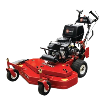
Exmark METRO Setup Instructions
Hide thumbs
Also See for METRO:
- Operator's manual (60 pages) ,
- Parts manual (20 pages) ,
- Setup instructions (5 pages)
Advertisement
Loose Parts
Use the chart below to verify that all parts have been shipped. Part numbers not shown are available on the dealer
extranet.
Dealer Pack
Part #
323-4
3290-357
1-633023
322-3
3256-23
1-805005
1-633349
3296-47
323-6
3296-39
1-806003
1-808286
1-806003
322-9
3296-29
1-303287
—
103-2106
1-603511
Literature Pack
Part #
—
—
—
Uncrating the Unit
1. Leaving the unit on the pallet, place the upper handle
assembly, the fuel tank, and the shifter lever at the
rear of the machine. Place the casters at the front
of the unit.
© 1997–2007—Exmark Mfg. Co., Inc.
P.O. Box 808
Beatrice, NE 68310
Description
Screw, HH 3/8-16 x 3/4 inch
Nut, Whizlock 3/8-16 inch
Stud, Fuel Tank
Screw, HH 5/16-18 x 3/4 inch
Washer, 5/16 inch SAE
Washer, Lock 5/16 inch Heavy
Spring, Compression
Nut, Nyloc 5/16-18 inch Thin
Screw, HH 3/8-16 x 1 inch
Nut, Nyloc 3/8-16 inch
Hairpin, Cotter
Pin, Clevis (Pistol Grip Only)
Hairpin, Cotter (Pistol Grip Only)
Screw, HH 5/16-18 x 1 3/4 inch (ECS
Only)
Nut, Nyloc 5/16-18 inch (ECS Only)
Tie, Cable
Warranty Registration Form
Key, Exmark Logo
Key, Standard
Description
Manual, Operator's
Manual, Parts
Manual, Engine Operator's
Qty.
8
Installing the front caster wheels.
8
2
2
4
Installing the fuel tank.
2
2
2
4
Installing the handle assembly.
4
2
Install the PTO engagement linkage.
2
2
Installing and adjusting the wheel
drive linkages.
2
2
2
Connecting wire harness.
1
Fill out warranty registration form and
1
place keys into literature pack.
1
Qty.
1
Read before operating the machine.
1
For units with 15hp Kawasaki engines.
1
Read before operating the machine.
2. Place a length of 4 inch x 4 inch (10 cm x 10 cm)
block between the front of the mower deck and the
pallet.
METRO
Setup Instructions
For Serial Nos. 720,000 & Higher
Use
Use
Part No. 4500-279 Rev. A
Printed in the USA.
All Rights Reserved
®
Advertisement
Table of Contents

Related Manuals for Exmark METRO


Summary of Contents for Exmark METRO
- Page 1 Place the casters at the front of the unit. © 1997–2007—Exmark Mfg. Co., Inc. Part No. 4500-279 Rev. A P.O. Box 808 Printed in the USA.
-
Page 2: Installing The Front Caster Wheels
3. Remove the bolt bag from under the mower deck belt shield. 4. Refer to the parts manual to help you identify and locate the parts and their proper position. Installing the Front Caster Wheels Install the casters to the front of the deck using eight 3/8-16 x 3/4 inch bolts and eight 3/8 inch whizlock nuts. - Page 3 2. Attach the inner wire of the throttle cable to the top hole in the throttle control lever as shown in Figure 3. 3. Loosen the clamp, place the cable behind it, and pull on the cable to move the throttle linkage to the full throttle position.
- Page 4 Figure 6 3. Adjustment slots 1. Shifter lever 2. Equal distance Figure 8 1. 3/16 inch to 1/4 inch (4.7mm to 6.4mm) Installing and Adjusting the Wheel 2. Neutral lock/park brake latch 3. Drive linkage Drive Linkages Note: The neutral lock/park brake latch clearance For Pistol Grip Handles: should be checked where there is a slight upward 1.
-
Page 5: Adjusting The Brakes
Adjusting the Brakes 2. Thread the drive lever linkage into the swivel located on the wheel drive idler arm. Thread the drive lever 1. Adjust the park brake by rotating the wingnut on the linkage in until the flat edge of the drive lever aligns upper end of each brake rod. - Page 6 Greasing the Unit 2. Check the brake for correct adjustment: A. Place the drive levers in the “park Note: The unit is not greased at the factory. brake”position. The mower should not Lubricate fittings with NGLI grade #2 multi-purpose move forward or backward. If it does, tighten gun grease.
-
Page 7: Servicing The Engine
Figure 14 48 inch Deck Shown for Reference Only Servicing the Engine Refer to Engine Owner’s Manual. Filling Out the Warranty Registration Form Fill out warranty registration form and place keys into literature pack.
Need help?
Do you have a question about the METRO and is the answer not in the manual?
Questions and answers