Exmark METRO Setup Instructions
Hide thumbs
Also See for METRO:
- Operator's manual (60 pages) ,
- Parts manual (20 pages) ,
- Setup instructions (7 pages)
Advertisement
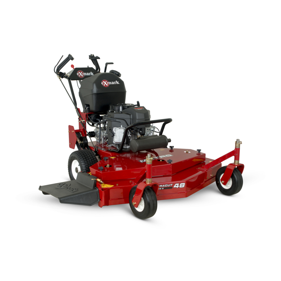
Loose Parts
Note: Use the chart below to verify that all parts have been shipped.
109-2590
Dealer Pack
Part #
Description
103-1309
Warranty Registration Form
103-2106
Key, Exmark Ignition
1-603511
Key, Standard Ignition
323-4
Screw, HH 3/8-16 x 3/4
3290-357
Nut, Whizlock 3/8-16
1-633023
Stud, Fuel Tank
322-3
Screw, HH 5/16-18 x 3/4
3256-23
Washer, 5/16 SAE
1-805005
Washer, Lock 5/16 Heavy
1-633349
Spring, Compression
3296-47
Nut, Nyloc 5/16-18 Thin
323-6
Screw, HH 3/8-16 x 1
3296-39
Nut, Nyloc 3/8-16
1-806003
Hairpin, Cotter
1-808286
Pin, Clevis
1-806003
Hairpin, Cotter
322-9
Screw, HH 5/16-18 x 1 3/4
3296-29
Nut, Nyloc 5/16-18
1-303287
Tie, Cable 5 1/2 (Small)
109-0623
Literature Pack
Part #
Description
109-9911
Manual, Operator's
109-9910
Manual, Parts
103-5466
Manual, Engine Operator's
Uncrate Unit
1. Leaving it on the pallet, place upper handle
assembly, fuel tank, and shifter lever at the rear
of the machine. Place casters at the front of the
unit.
2. Place a length of 4" x 4" (10x10 cm) block
between the front of the mower deck and the
pallet.
3. Remove the bolt bag from under the mower deck
belt shield.
4. Refer to Parts Manual to help you identify and
locate parts and their proper position.
SETUP INSTRUCTIONS
Qty
Use
2
Fill out and return to Exmark
1
Unit ignition
1
8
Components to install the Front Caster Wheels
8
2
2
4
Components to install fuel tank
2
2
2
4
Components to install handle assembly
4
Component to install the blade engagement linkage
2
and speed control rod assembly
2
Units with Pistol Grip Handles: Components to
install wheel drive linkages
2
2
Units with ECS Handles: Components to install
wheel drive linkages
2
2
For fastening wiring harness to handle assembly
Qty
Use
1
Read before operating machine
1
1
For units with 15HP Kawasaki engines
Installing the Front Caster Wheels
1. Install casters to front of deck using eight 3/8-16
x 3/4 bolts and eight 3/8" whizlock nuts. Tighten
the lower four bolts first, then the top four.
Positioning the Discharge Chute
1. Loosen the two (2) 5/16 nyloc nuts attaching
discharge chute. Lower the discharge chute into
position. Retighten nyloc nuts until chute is
snug but can pivot freely.
METRO
For Serial Nos. 600,000 and Higher
Page 1 of 5
109-2020 Rev. A
Advertisement
Table of Contents

Related Manuals for Exmark METRO


Summary of Contents for Exmark METRO
- Page 1 Note: Use the chart below to verify that all parts have been shipped. 109-2590 Dealer Pack Part # Description 103-1309 Warranty Registration Form Fill out and return to Exmark 103-2106 Key, Exmark Ignition Unit ignition 1-603511 Key, Standard Ignition 323-4...
- Page 2 Installing the Fuel Tank 1. Apply retaining adhesive “Fel-Pro ProLock Retaining I or Retaining II” or “Loctite RC 609 or 680” on the two threaded studs from the bolt bag and install into the two left holes underneath fuel tank. Install the fuel tank on top of the fuel tank support with the studs going through the slots in the support.
- Page 3 Install and adjust shifter lever Install and adjust wheel drive linkages 1. Remove the 3/8” nyloc nut and spring disk washer from the stud on top of the transmission. For Pistol Grip Handles: Install the shifter lever through slot in shifter lever 1.
-
Page 4: Adjusting The Brakes
For ECS Handles: ROTATE FORWARD 1. Locate the drive lever linkages which have the FOR PARK BRAKE balljoint and jam nuts installed on one end. POSITION Locate the (2) 5/16-18 x 1 3/4 Hex cap screws ROTATE BACK FOR and (2) 5/16-18 nyloc nuts in the bolt bag. NEUTRAL LOCK Thread drive lever linkage into the swivel located POSITION... -
Page 5: Installing The Muffler
Connecting Wire Harness 1. Route the long, unattached wiring harness lead up the left hand side of the handle and connect the flag terminals, in any order, to the operator presence control switch terminals on the inside of the control console. 2.
Need help?
Do you have a question about the METRO and is the answer not in the manual?
Questions and answers