
Related Manuals for New Holland LS35-16H


Summary of Contents for New Holland LS35-16H
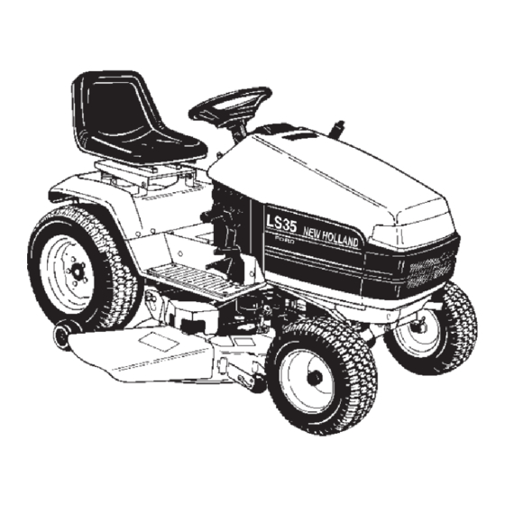
- Page 1 NEW HOLLAND OPERATOR’S MANUAL LS35–16H Yard Tractor Model No. 715692016 – T2B0501 & Up Publications Number: 86729767 4/02...
-
Page 2: Table Of Contents
Using the Attachment Lift Lever ... . . All of us at New Holland want you to be completely Adjusting the Dial-A-Height .... -
Page 3: Safety
This product is capable of amputating hands and feet and throwing objects. Always follow all safety instructions to Model No: avoid serious injury or death. Serial No. General Operation Read, understand, and follow all instructions in the Read this manual carefully to learn how to operate and operator ’s manual and on the machine before starting. -
Page 4: Riding Mower Safety
Never assume that them. children will remain where you last saw them. Use only genuine New Holland replacement parts to Keep children out of the mowing area and under the ensure that original standards are maintained. - Page 5 Battery gases can explode. Keep cigarettes, sparks and flames away from battery. Use only genuine replacement parts to ensure that original standards are maintained. Use only New Holland approved attachments. Warranty may be voided if used with unapproved attachments. Do not mow across slopes exceeding 5 degrees.
-
Page 7: Slope Chart
Slope Chart... -
Page 9: Safety And Instruction Decals
Safety and Instruction Decals Safety decals and instructions are easily visible to the operator and are located near any area of potential danger. Replace any decal that is damaged or lost. TR112168 TR92D6726 TR78D9740 1. Cutting blade TR92D6727 1. Fuel levels 2. - Page 10 TR92D8946 TR93D0302 TR92D6738 1. Pull the knob out to start 2. Push the knob in to stop the PTO. the PTO. TR94D1863 TR99D2985 TR99D8038 1. Mowing in reverse 2. Power Take-off (PTO) TR92D6739 enabled.
- Page 11 TR104D4163 TR99D8894 1. Explosion hazard 4. Wear eye protection 2. No fire, open flames, or 5. Read the Operator’s smoking. Manual. 3. Caustic liquid/chemical 6. Keep bystanders a safe burn hazard distance from the battery. TR104D5091 1. Contains lead; do not 3.
-
Page 12: Gasoline And Oil
Gasoline and Oil Recommended Gasoline Stabilizer/Conditioner Use UNLEADED Regular Gasoline suitable for Using a stabilizer/conditioner in the machine: automotive use (85 pump octane minimum). Leaded Keeps gasoline fresh during storage of 90 days or less. regular gasoline may be used if unleaded regular is not For longer storage it is recommended that the fuel tank available. -
Page 13: Operation
Operation Setting the Parking Brake Think Safety First 1. Push the brake pedal (Fig. 2) down and hold it in the Please carefully read all the safety instructions. Knowing depressed position. this information could help you, your family, pets or bystanders avoid injury. -
Page 14: Operating The Power Take Off (Pto)
6. Turn the ignition key and hold it in the start position (Fig. 5). When the engine starts, release the key. Important If the engine does not start after 10 seconds of continuous cranking, turn the ignition key to off and let the starter motor cool for 60 seconds;... -
Page 15: Checking The Safety Interlock System
You rise from the seat when the brake pedal is released You rise from the seat when the power take off (PTO) is on. You move the hydro control pedal out of the neutral position when the parking brake is engaged. You shift into reverse with the power take off (PTO) engaged. -
Page 16: Indicator Control Module
3. Set the parking brake, move the power take off (PTO) to off and move the hydro control pedal forward from the neutral; the engine should not crank. 4. Set the parking brake and move the power take off (PTO) to off. Now start the engine. While the engine is running, release the parking brake and rise slightly from the seat;... -
Page 17: Driving Forward Or Backward
interlock system is deactivated. The light goes out whenever the power take off (PTO) is disengaged or the engine is shut off. PTO (Power Take Off) The PTO (power take off) light will be on when the key is in the run or lights positions and the PTO (power take off) is engaged on. -
Page 18: Adjusting The Dial-A-Height
2. Pull attachment lift lever rearward until latch locks. In 1. Pull the seat adjustment lever toward the rear to this position the lift will hold the attachment in the up, release the lock (Fig. 12). or raised position. 2. Slide the seat to the desired position and release the lever to engage lock. -
Page 19: Pushing The Machine By Hand
3. For quick stops, just press on the brake pedal. This automatically disengages the cruise control and applies the brake at the same time. Pushing the Machine by Hand Important Always push the machine by hand. Never tow the machine because transaxle damage may occur. 1203b To Push the Machine Figure 14... -
Page 20: Maintenance
Maintenance Recommended Maintenance Schedule Maintenance Service Maintenance Procedure Interval After First Use Change oil Check oil level Check safety system Each Use Check brake Clean outside of engine Every 5 Hours Check battery electrolyte Service foam air cleaner Check spark plug(s) Every 25 Hours Check tire pressure Check front wheel toe-in... -
Page 21: Servicing The Air Cleaner
Caution If you leave the key in the ignition switch, someone could accidently start the engine and seriously injure you or other bystanders. Remove the key from the ignition and disconnect the wire from the spark plug before you do any maintenance. -
Page 22: Servicing The Engine Oil
Note: Make sure the rubber seal is flat against the air cleaner base and cover. 3. Install the air cleaner cover (Fig. 17). 4. Close the hood. Servicing the Engine Oil 1213 Service Interval/Specification Figure 18 1. Foam element 2. Oil Change oil: After the first 5 operating hours. - Page 23 7. Slowly pour approximately 80% of the specified amount of oil into the filler tube (Fig. 20). Now check the oil level; refer to Checking Oil Level, page 22. Slowly add additional oil to bring to full mark on dipstick. Changing the Oil Filter Replace the oil filter every 200 hours or every other oil change.
-
Page 24: Servicing The Spark Plug
Servicing the Spark Plug Service Interval/Specification Check the spark plug(s) after every 200 operating hours. 0.040in. Make sure the air gap between the center and side (1.02 mm) electrodes is correct before installing the spark plug. Use a spark plug wrench for removing and installing the spark plug(s) and a gapping tool/feeler gauge to check and adjust the air gap. -
Page 25: Checking The Tire Pressure
2323 1211 Figure 27 1. Valve stem Figure 25 Servicing the Brake 3. Lubricate the traction control pedal on hydrostatic models (or brake and clutch pedals on gear drive Always set the parking brake when you stop the machine models) where they pivot on mounting shaft (Fig. 26). or leave it unattended. -
Page 26: Servicing The Fuel Tank
6. Check the brake operation again; refer to Checking the Brake, page 25. Important With the parking brake released, the rear wheels must rotate freely when you push the mower. If the 0.015 in. (.38 mm) clearance and free wheel rotation cannot be achieved contact your service dealer immediately. -
Page 27: Adjusting The Front Wheel Toe-In
Replacing the Fuel Filter 2. Push front tires out, at front, to remove normal looseness in the linkage. Never install a dirty filter if it is removed from the fuel 3. Measure, between the rims, at spindle level, in the line. -
Page 28: Servicing The Transaxle Fluid
Servicing the Transaxle Fluid 3. Rotate the bulb holder 1/4 turn counterclockwise and remove it from the reflector (Fig. 34). Service Interval/Specification 4. Push and rotate the bulb counterclockwise until it stops (approx. 1/4 turn) and remove bulb from the bulb The transaxle is a sealed system and no checking or holder (Fig. -
Page 29: Servicing The Battery
3. Push the wire connectors onto the terminals on the Warning bulb holder. Incorrect battery cable routing could damage the Servicing the Battery tractor and cables causing sparks. Sparks can cause the battery gasses to explode, resulting in Warning personal injury. Always DISCONNECT the negative (black) Battery posts, terminals, and related accessories battery cable before disconnecting the positive... - Page 30 Installing the Battery 1. Install the battery into the tractor (Fig. 37). 2. Secure battery with hold down strap (Fig. 36). 3. Using the bolt and nut, connect the positive (red cover) cable to the positive (+) battery post (Fig. 36). Slide the rubber cover over the battery post.
- Page 31 6. Reinstall battery vent caps. Charging the Battery Warning Charging the battery produces gasses that can explode. Never smoke near the battery and keep sparks and flames away from battery. Important Always keep the battery fully charged (1.265 specific gravity). This is especially important to prevent battery damage when the temperature is below 32 F (0 C).
-
Page 32: Wiring Diagram
Wiring Diagram... -
Page 33: Cleaning And Storage
Cleaning and Storage D. Restart engine and run it until it stops. E. Choke or prime the engine. Start and run engine 1. Disengage the power take off (PTO), set the parking until it will not start. Operate primer, if equipped brake, and turn the ignition key to off. -
Page 34: Troubleshooting
Troubleshooting Problem Possible Causes Corrective Action Starter does not crank 1. Blade control (PTO) is 1. Move blade control (PTO) to ENGAGED. DISENGAGED. 2. Parking brake is not on. 2. Set parking brake. 3. Operator is not seated. 3. Sit on the seat. 4. - Page 35 Problem Possible Causes Corrective Action Abnormal vibration. 1. Engine mounting bolts are 1. Tighten engine mounting bolts. loose. 2. Loose engine pulley, idler 2. Tighten the appropriate pulley. pulley, or blade pulley. 3. Engine pulley is damaged. 3. Contact Authorized Service Dealer.
- Page 36 Publication No. 86729767 Form No. 3327–429 New Holland North America, Inc., New Holland, PA Printed in U.S.A.
Need help?
Do you have a question about the LS35-16H and is the answer not in the manual?
Questions and answers
How to adjust the steering gear and rack on a New Holland LS35
To adjust the steering gear and rack on a New Holland LS35, follow these steps related to adjusting the front wheel toe-in:
1. Check the toe-in before making any adjustments.
2. Remove the ball joint from one steering lever.
3. Loosen the jam nut securing the ball joint to the steering rod.
4. Rotate the ball joint:
- Clockwise to increase toe-in.
- Counterclockwise to decrease toe-in.
5. Hold the flats on the ball joint aligned with the tie rod and tighten the jam nut.
6. Reinstall the ball joint to the steering lever and recheck the toe-in.
Important: If more than one turn is needed to meet specifications, alternate adjustments between the left and right steering rods to keep the steering wheel centered. Maintain the correct toe-in of the front wheels.
This answer is automatically generated
How to adjust the steering gear and rack on a New Holland LS 35
To adjust the steering gear and rack on a New Holland LS35, follow these steps for adjusting the front wheel toe-in:
1. Check the toe-in before making adjustments.
2. Remove the ball joint from one steering lever.
3. Loosen the jam nut securing the ball joint to the steering rod.
4. Rotate the ball joint:
- Clockwise to increase toe-in.
- Counterclockwise to decrease toe-in.
5. Hold the flats on the ball joint aligned with the tie rod and tighten the jam nut.
6. Reinstall the ball joint to the steering lever and recheck the toe-in.
If more than one full turn is needed, alternate adjustments between the left and right steering rods to keep the steering wheel centered. Maintain the specified toe-in for proper steering operation.
This answer is automatically generated
How does the belt go on my mower it's a ls35 new Holland