Subscribe to Our Youtube Channel
Summary of Contents for Must PV1100 PLUS Series
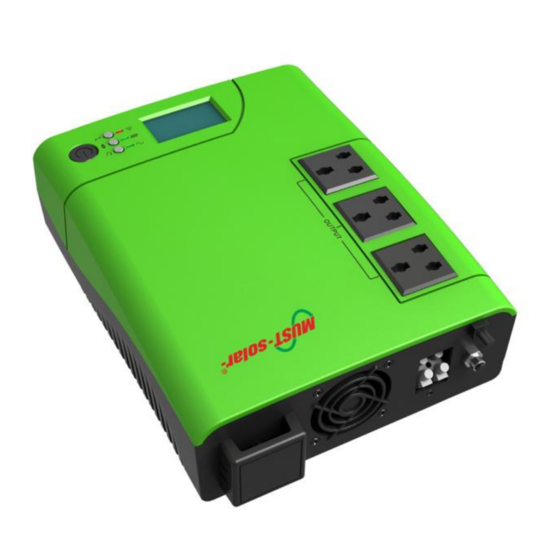
- Page 1 Service Manual PV1100 PLUS Series (1200VA/1800VA/2400VA) Solar Inverter/Charger PV1100 PLUS (1200VA/1800VA/2400VA)
-
Page 2: Table Of Contents
Service Manual PV1100 PLUS Series (1200VA/1800VA/2400VA) Table of Contents 1. General Information………………………………………………….......1 1.1 Brief Introduction………………………………………………………………….……1 1.2 Inverter Schematic Diagram………………………………………………………….1 1.3 Inverter Components Instructions............... 2 2. Fault Code........................3 3. Maintenance......................4 4. Fault Symptom ......................4 4.1 Inverter Failure in Starting..................4 4.2 PV Failure in Charging..................5 4.3 Fault Code 00/01 When Starting Inverter............6... -
Page 3: General Information
Service Manual PV1100 PLUS Series (1200VA/1800VA/2400VA) 1. General Information 1.1 Brief introduction This manual mainly introduces the maintenance methods of PV11-1200 model, disassembly and some attention; please refer to PV11-1200 maintenance manual when repairing PV11-1800/PV11-2400. 1.2 Inverter Schematic Diagram INVERTER... -
Page 4: Inverter Components Instructions
Service Manual PV1100 PLUS Series (1200VA/1800VA/2400VA) 1.3 Inverter Components Instructions Figure 1.6 Figure 1.1 Battery Reverse Protection Part Control Board PV Charger Main Board Board Figure 1.8 Button Board Figure 1.4 LCD Screen Figure 1.5 Figure 1.2 Figure 1.7 Figure 1.2... -
Page 5: Fault Code
Service Manual PV1100 PLUS Series (1200VA/1800VA/2400VA) 2. Fault Code Note: No.00-No.07 is fault code; No.10-No.16 is warning code Fault Code Description Output short circuit Output overload Battery damaged Inverter output volt is over 280VAC Inverter output volt is below 170VAC... -
Page 6: Maintenance
PV1100 PLUS Series (1200VA/1800VA/2400VA) 3. Maintenance Note: When repairing, in order to avoid second damage caused by large current, you must use DC power supply analog battery to connect to open the inverter, and make sure the current is below 3A. -
Page 7: Pv Failure In Charging
Service Manual PV1100 PLUS Series (1200VA/1800VA/2400VA) D. Main Board MOS Broken when Boosting (Figure 1.2) Position Type Normal Value Failure Status Main board Q1-Q7 Boost reversely Short circuit or other between D-S 0.248 value Note: If confirmed MOS broken, need to check if relative drive resistor is burned, broken resistor value is larger than normal one. -
Page 8: Fault Code 00/01 When Starting Inverter
Service Manual PV1100 PLUS Series (1200VA/1800VA/2400VA) C. PV Charger Board (Figure 1.8) Position Type Normal Value Failure Status PV charger board Triode Boost 0.660 Short circuit or big gap Q7\Q8\Q9 compared with normal value 4.3 Fault Code 00/01 When Starting Inverter Possible Reasons as follows A. -
Page 9: Fault Code 03
Service Manual PV1100 PLUS Series (1200VA/1800VA/2400VA) 4.5 Fault Code 03 Possible Reasons as Follows A. One group of output invert MOS on main board doesn’t work (Figure 1.3) Position Type Normal Value Failure Status Main board Q8-Q16 Boost reversely Short circuit or other between D-S 0.515... -
Page 10: Fault Code 14
Service Manual PV1100 PLUS Series (1200VA/1800VA/2400VA) 4.9 Fault Code 07 Possible Reasons as Follows A. Fan is broken. B. Fan is blocked. 4.10 Fault Code 10 Possible Reasons as Follows A. PV charger board charge MOS is broken, current is not limited (Figure 1.5) - Page 11 Service Manual PV1100 PLUS Series (1200VA/1800VA/2400VA) 4.12 Fault Code 14 Possible Reasons as Follows A. Utility frequency is below 40Hz or over 70Hz Position Type Normal Value Failure Status Utility input socket Socket 40-70 Hz Beyond normal value 4.13 Fault Code 15 Possible Reasons as Follows A.
-
Page 12: Inverter Disassemble & Assemble
Service Manual PV1100 PLUS Series (1200VA/1800VA/2400VA) 5. Inverter Disassemble & Assemble 5.1 Take out the 5 screws in the inverter bottom side, then you can open the unit; 5.2 Take off the connection cable of LCD and button board; 5.3 Dis-assembly battery reverse protection board, take off all cables on main board;...


Need help?
Do you have a question about the PV1100 PLUS Series and is the answer not in the manual?
Questions and answers