Table of Contents
Advertisement
Advertisement
Table of Contents

Related Manuals for Must PV18 MPPT 3 KW


Summary of Contents for Must PV18 MPPT 3 KW
- Page 1 3KW~5KW 420-00314-A1...
-
Page 2: Table Of Contents
Table of Contents Appendix: Approximate Back-up Time Table Load(W) Backup Time@48Vdc 100Ah(min) Backup Time@48Vdc 200Ah(min) Model 1054 2107 1054 ABOUT THIS MANUAL ......................1 Purpose ......................... .1 1200 Scope ..........................1 1500 1800 SAFETY INSTRUCTIONS ....................1 2100 INTRODUCTION .......................2 2400 Features ..........................2 2700... -
Page 3: About This Manual
TROUBLE SHOOTING ABOUT THIS MANUAL Purpose What to do Problem Explanation / Possible cause LCD/LED/Buzzer This manual describes the assembly, installation, operation and troubleshooting of this unit. Please read this manual LCD/LEDs and buzzer Unit shuts down carefully before installations and operations. Keep this manual for future reference. will be active for 3 The battery voltage is too low 1. -
Page 4: Introduction
INTRODUCTION This is a multi-function inverter/charger, combining functions of inverter, solar charger and battery charger to offer uninterruptible power support with portable size. Its comprehensive LCD display offers user-configurable and easy-accessible button operation such as battery charging current, AC/solar charger priority, and acceptable input voltage based on different applications. -
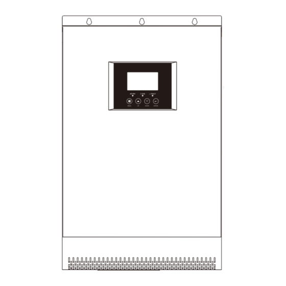
Page 5: Product Overview
Product Overview Low DC Cut-off Voltage @ load < 20% 42.0Vdc @ 20% ≤ load < 50% 40.8Vdc @ load ≥ 50% 38.4Vdc High DC Recovery Voltage 58Vdc High DC Cut-off Voltage 60Vdc No Load Power Consumption <50W Table 3 Charge Mode Specications Utility Charging Mode INVERTER MODEL 3KW~5KW... -
Page 6: Installation
INSTALLATION Line mode: Circuit Breaker Output Short Circuit Protection Unpacking and Inspection Battery mode: Electronic Circuits Before installation, please inspect the unit. Be sure that nothing inside the package is damaged. You should have Efficiency (Line Mode) >95%(Rated R load, battery full charged) received the following items inside of package: 10ms typical (UPS,VDE) The unit x 1... -
Page 7: Battery Connection
SPECIFICATIONS Table 1 Line Mode Specifications WARNING! All wiring must be performed by a qualified personnel. WARNING! It's very important for system safety and efficient operation to use INVERTER MODEL 3KW~5KW appropriate cable for battery connection. - Page 8 CAUTION!! Do not apply anti-oxidant substance on the terminals before terminals are connected tightly. CAUTION!!Before making the final DC connection or closing DC breaker/disconnector, be sure positive (+) must be connected to positive (+) and negative (-) must be connected to negative (-). The inverter stop working if...
-
Page 9: Ac Input/Output Connection
Icon flashing Warning Code Warning Event WARNING! All wiring must be performed by a qualified personnel. WARNING! It's very important for system safety and efficient operation to use appropriate cable for AC input Fan is locked when inverter is on. - Page 10 CAUTION: Before connecting to PV modules, please install separately a DC circuit breaker between inverter and PV Inverter load current sensor error modules. WARNING! All wiring must be performed by a qualified personnel. Inverter grid over current error WARNING! It's very important for system safety and efficient operation to use appropriate cable for PV module connection.
- Page 11 Recommended PV module configuration Backlight on Backlight off (default) Maximum Power (Pmaxl) 250W Max. PV module numbers in series 2 30.9 x 2 =56~72 → Backlight control Max. Power Voltage Vmpp(V) 30.9V Max. Power Current Impp(A) Alarm off 8.42A Alarm on (default) PV module numbers in parallel 8 60 A/8.42 Total PV module →...
- Page 12 30A (default) Setting range is from 1A to 60A. Maximum utility charging current Increment of each click is 1A. AGM (default) Flooded LEAD Battery type Lithium Ion User-Defined If "User-Defined" LI is selected, battery charge voltage and low DC cut-off voltage can be set up in program 17, 18 and 19. 48V model default setting: 56.4V Bulk charging voltage If self-defined is selected in program 14, this program can be set...
- Page 13 Solar energy provides power to the loads as first priority. If the battery voltage is lower than the setting point in program 20, the solar energy will never supply to the load or feed into the grid, only charge the battery. If the battery voltage is higher than the setting point in program 20, the solar energy will supply to the load or feed...
-
Page 14: Final Assembly
Final Assembly Solar energy provides power to the After connecting all wirings, please put bottom cover back by screwing two screws as shown below. loads as first priority. If battery voltage has been higher than the setting point in program 21 for 5 minutes, and the solar energy has been available for 5 minutes too, the inverter will turn to battery mode, solar and... -
Page 15: Operation
LCD Setting OPERATION After pressing and holding "ENTER" button for 2 seconds, the unit will enter setting mode. Press "UP" or "DOWN" Power ON/OFF button to select setting programs. And then, press "ENTER" or "MENU" button to confirm the selection and exit. Setting Programs: Program Description... -
Page 16: Lcd Setting
LCD Display Icons In battery mode, it will present battery capacity. Load Percentage Battery Voltage LCD Display <1.717V/cell 1.717V/cell~1.8V/cell Load >50% 1.8V/cell~1.883V/cell >1.883 V/cell <1.817V/cell Function description Icon Input Source Information and Output Information 1.817V/cell~1.9V/cell Iindicates the AC information 50%> Load>20% 1.9 V/cell ~1.983V/cell Indicates the DC information Indicate input voltage, input frequency, PV voltage, battery voltage and charger current.
Need help?
Do you have a question about the PV18 MPPT 3 KW and is the answer not in the manual?
Questions and answers