Advertisement
Table of Contents
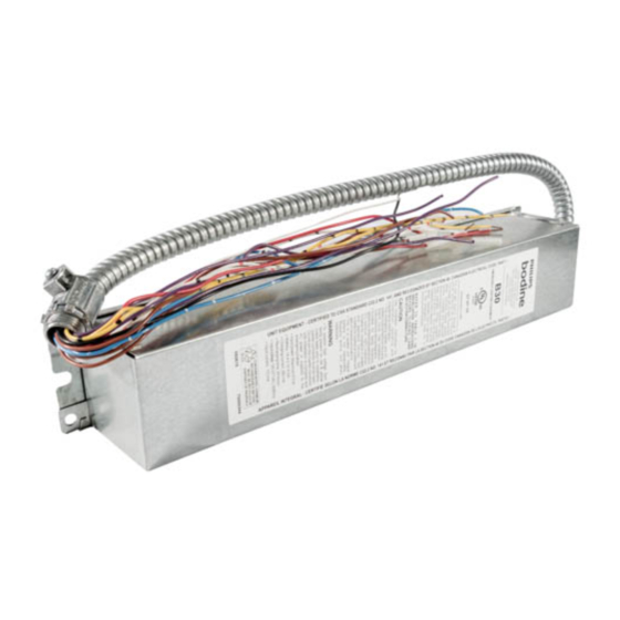
B30
Installation Instructions
EMERGENCY LIGHTING EQUIPMENT
! IMPORTANT SAFEGUARDS !
READ AND FOLLOW ALL SAFETY INSTRUCTIONS
1. To prevent high voltage from being present on red & yellow output leads prior to installation, inverter
connector must be open. Do not join inverter connector until installation is complete and AC power is
supplied to the emergency ballast.
2. This product is for use with most 2' through 8' (17 W - 215 W) T5, T8, T9, T10 and T12 single pin or
bipin fluorescent lamps, including energy saving, circline, U-shaped and rapid-start (4-pin) long
compact fluorescent lamps.
3. Make sure all connections are in accordance with the National Electrical Code or Canadian Electrical Code
and any local regulations.
4. To reduce the risk of electric shock, disconnect both normal and emergency power supplies and battery
connector of the emergency ballast before servicing.
5. This emergency ballast is for factory or field installation.
6. This product is suitable for damp locations where the ambient temperature is +5°C minimum, +50°C
maximum. Not suitable for heated air outlets and wet or hazardous locations.
7. An unswitched AC power source is required (120 or 277 VAC, 60 Hz).
8. Do not install near gas or electric heaters.
9. The use of accessory equipment not recommended by the manufacturer may cause an unsafe
condition.
10. Do not use this product for other than intended use.
11. Servicing should be performed by qualified service personnel.
CAUTION: Verify that all replacement lamp types marked on the installed luminaire are also identified as suitable for
use with this inverter/charger pack.
THIS PRODUCT CONTAINS A RECHARGEABLE NICKEL-CADMIUM BATTERY.
236 Mt. Pleasant Rd. • Collierville, TN USA 38017-2752 • Tech Support 888-263-4638 • Fax 901-854-1630 • www.philips.com/bodine
SAVE THESE INSTRUCTIONS
THE BATTERY MUST BE RECYCLED OR DISPOSED OF PROPERLY.
© Philips Emergency Lighting
A Division of Philips Electronics North America Corporation
WHEN USING ELECTRICAL EQUIPMENT, BASIC
SAFETY PRECAUTIONS SHOULD ALWAYS BE
FOLLOWED, INCLUDING THE FOLLOWING:
Ni - Cd
12/10/13
73000001
NRTL/C
Advertisement
Table of Contents

Related Manuals for Philips bodine B30


Summary of Contents for Philips bodine B30
- Page 1 THE BATTERY MUST BE RECYCLED OR DISPOSED OF PROPERLY. 12/10/13 © Philips Emergency Lighting A Division of Philips Electronics North America Corporation 236 Mt. Pleasant Rd. • Collierville, TN USA 38017-2752 • Tech Support 888-263-4638 • Fax 901-854-1630 • www.philips.com/bodine 73000001...
-
Page 2: Installation
INSTALLATION WARNING: TO PREVENT HIGH VOLTAGE FROM BEING PRESENT ON RED & YELLOW OUTPUT LEADS PRIOR TO INSTALLATION, INVERTER CONNECTOR MUST BE OPEN. DO NOT JOIN INVERTER CONNECTOR UNTIL INSTALLATION IS COMPLETE AND AC POWER IS SUPPLIED TO THE EMERGENCY BALLAST. NOTE: Make sure that the necessary branch circuit wiring is available. -
Page 3: Operation
Switched Fixtures Unswitched Fixtures WALL SWITCH WHT/RED WHT/RED VIOLET VIOLET(+) VIOLET VIOLET(+) BROWN BROWN(-) BROWN BROWN(-) BLACK 120V BLACK 120V BLACK BLACK ORANGE 277V ORANGE 277V (CAP UNUSED LEAD) (CAP UNUSED LEAD) COMMON WHITE COMMON WHITE WHT/BLK WHT/BLK BLACK BLACK WHITE WHITE Breaking Hot... -
Page 4: Wiring Diagrams
Table 1 - Lamp Compatibility WIRING DIAGRAMS LAMP DIAMETER BASE WATTAGE NO. of LAMPS BROWN (T8, T9, T10, T12) (Length) (EMERGENCY) CONNECTOR CLOSED Single 17 - 40 W (2’ - 4’) OPEN 1”, 1¼”, 1½” The following diagrams are typical schematics only. 32 - 215 W (5' -8') OPEN Bipin... - Page 5 WIRING DIAGRAMS FOR 1-LAMP EMERGENCY OPERATION WIRING DIAGRAMS FOR 1-LAMP EMERGENCY OPERATION FIG K TWO (2) LAMP RAPID START STEP DIMMING BALLAST THE WHITE/BLACK LEAD MUST CONNECT TO THE WHITE BROWN INVERTER WARNING: Refer to Table 1 before connecting BROWN CONNECTOR LEAD OF THE STEP-DIMMING BALLAST ASSOCIATED WITH WHITE...
Need help?
Do you have a question about the bodine B30 and is the answer not in the manual?
Questions and answers