Advertisement
Quick Links
Advertisement

Related Manuals for Mr.Ken MELA


Summary of Contents for Mr.Ken MELA
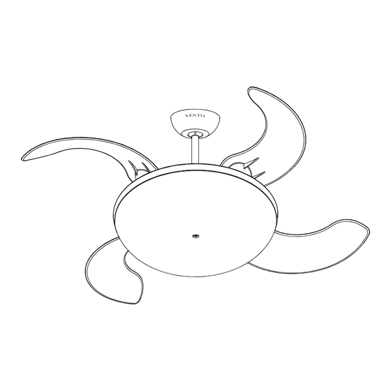
- Page 1 ASSEMBLY AND INSTALLATION MANUAL OF CEILING FAN MELA...
-
Page 2: Important Safety Instructions
I. IMPORTANT SAFETY INSTRUCTIONS Installation must be carried out by a qualified electrician. Turn off the electrical mains at the circuit breaker/fuse box. Do not use power supply other than 220V / 50Hz. This appliance must be earthed. When mounting the fan, ensure that the safety wire is looped across the mounting bracket. The mounting bracket must be able to withhold a min. - Page 3 II. FOR YOUR CONVENIENCE ON ASSEMBLY & INSTALLATION, PLEASE FOLLOW THIS MANUAL DESCRIPTION 1. Tools: Philips Screwdriver Slotted Screwdriver Adjustable wrench Cutter Ladder Install the power cord in accordance with the cord Check if all parts and accessories are present: Mounting Bracket Remote Control Screw Pack...
-
Page 4: Installation Instruction
III. INSTALLATION INSTRUCTION ATTENTION: Do not install the fan onto the partition ceiling or chapped wall. The ceiling fan must be mounted at a min. height of 7.5ft/2.3m of clearance from the floor. 2. 3m Floor The mounting bracket must be securely fastened to a structural ceiling member. NOTE: Make sure all screws are tightened. - Page 5 Before installation, remove two polyester bars from the fan body. Otherwise, the fan will not function properly. Polyester Bar Polyester Bar Loosen 2 screws at the yoke of the motor assembly. Slide the canopy into the downrod. Thread the power leads from the fan through the canopy and downrod (take extra care not to pull power wires damage).
- Page 6 Tighten the two downrod set screws to make sure the fan run stably. Then, install downrod (ball part) into mounting bracket opening that already securely fastened to a structural ceiling member. The tab opposite of the mounting bracket opening should fit in slot on ball.
- Page 7 Plug G10Q 40W assembly chart After locking the canopy, loosen the screw on lampshade. Install T5 circular lamp into the spring clips, then push lamp holder into the T5 circular lamp socket. Align holes on lampshade to the fan body. Finally tighten the washers and screw with 6mm wrench.
- Page 8 IV. INSTALLATION INSTRUCTIONS FOR CEILING FAN REMOTE CONTROL A. IMPORTANT POINTS: Please read this manual and keep it for future use. Turn off the electrical mains at the circuit breaker/fuse box. Please note that all wiring connections should be done by a qualified electrician. This unit is to be used in an AC220V / 50Hz supply zone only.
- Page 9 V. CODE SWITCH SETTING These DIP code can be pushed upward and downward to change the setting. Both of these remote control components (receiver and transmitter) have a set of four switches that need to have the same settings. (The total combination becomes 16 frequency codes).
- Page 10 VI. WIRING FOR CEILING FAN INSTALLATION NOTE: a.) Incorrect wire connection may damage this fan and receiver. b.) Do not attempt to shorten the receiver’s antenna wire. A typical ceiling fan remote control is wired as shown in this wiring diagram. (Fig. 1) Make sure that the wire of brown/blue/orange is connected.
-
Page 11: Fuse Replacement
VII. FUSE REPLACEMENT Push both side of the fuse capsule towards each other and twist it to open the fuse capsule. Remove the damaged 5A glass fuse from the capsule then replace a new 5A glass fuse. To close the fuse capsule aline the latch and groove then push in and twist to lock the fuse capsule. -
Page 12: Troubleshooting
VIII. TROUBLE SHOOTING PROBLEM A: FAN WILL NOT START REMEDIES: Check fuse or circuit breaker and replace if necessary. Turn off electrical power, check all wire connections. Check to make sure the dip switches from the transmitter and receiver are set on the same frequency. PROBLEM B: FAN EXCESSIVELY NOISY REMEDIES: Check that all screws in fan assembly are tight and properly seated. - Page 13 B40519B KE...
Need help?
Do you have a question about the MELA and is the answer not in the manual?
Questions and answers