Table of Contents
Advertisement
We advise you to read this manual carefully, which contains all the instructions for
maintaining the appliance's aesthetic and functional qualities.
For further information on the product: www.smeg.com
Contents
46
46
50
50
50
50
51
52
52
53
53
54
55
56
56
58
58
59
59
61
65
65
68
69
76
76
76
77
78
78
78
80
81
81
83
86
45
Advertisement
Table of Contents

Related Manuals for Smeg A2PYID-81


Summary of Contents for Smeg A2PYID-81
-
Page 1: Table Of Contents
5 Installation 5.1 Electrical connection 5.2 Positioning 5.3 Instructions for the installer We advise you to read this manual carefully, which contains all the instructions for maintaining the appliance’s aesthetic and functional qualities. For further information on the product: www.smeg.com... -
Page 2: Instructions
Instructions 1 Instructions • Keep children under the age of 8 away from the appliance when it 1.1 General safety instructions is in use. • Cleaning and maintenance must Risk of personal injury not be carried out by unsupervised • During use the appliance and its children. - Page 3 Instructions • Do not place metal objects, such • DO NOT USE AEROSOLS IN as dishes or cutlery, on the hob THE VICINITY OF THIS surface during use as they may APPLIANCE WHILST IT IS IN overheat. USE. • Do not insert pointed metal objects •...
- Page 4 Instructions Risk of damaging the appliance • DO NOT FOR ANY REASON USE THE APPLIANCE AS A • Do not use abrasive or corrosive SPACE HEATER. detergents (e.g. scouring • Do not spray any spray products powders, stain removers and near the oven.
- Page 5 Instructions • If any liquid does boil over or spill, • Do not use rough or abrasive remove the excess from the hob. materials or sharp metal scrapers. • Take care not to spill acid • Do not use cleaning products substances such as lemon juice or containing chlorine, ammonia or vinegar on the hob.
-
Page 6: Identification Plate
Instructions • To avoid potential overheating, the 1.3 Manufacturer’s liability appliance must not be installed The manufacturer declines all liability behind a decorative door or a for damage to persons or property panel. caused by: • Have the electrical connection •... -
Page 7: Disposal
Instructions 1.6 Disposal • Deliver the appliance to the appropriate recycling centre for This appliance conforms to the electrical and electronic WEEE European directive (2012/19/EU) and must be equipment waste, or return it to the disposed of separately from other retailer when purchasing an waste at the end of its service life. -
Page 8: How To Read The User Manual
Instructions 1.7 How to read the user manual 1.8 To save energy This user manual uses the following reading • Only preheat the appliance if the conventions: recipe requires you to do so. • Unless otherwise indicated on the Instructions package, defrost frozen foods General information on this user before placing them in the oven. -
Page 9: Description
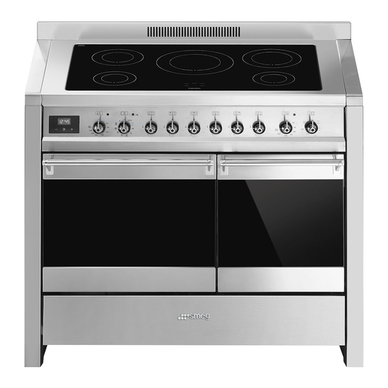
Description 2 Description 2.1 General description 1 Hob 2 Control panel 3 Inside lights 4 Seal 5 Main oven door 6 Auxiliary oven door 7 Fan 8 Storage compartment Rack/tray support frame shelf... -
Page 10: Hob
Description 2.2 Hob Pan Ø Dimensions Max. power Power draw in Zone minimum H x L (mm) draw (W)** booster function (W)** (mm)* 145 x 145 1400 2200 180 x 180 1850 3000 210 x 210 2300 3700 260 x 260 2600 3700 *Pans with smaller diameters can be detected as long as they are suitable for induction cooking. -
Page 11: Control Panel
Description 2.3 Control panel 1 Programmer clock 6 Hob cooking zone knobs Useful for displaying the current time, setting Useful for controlling the cooking zones of programmed cooking operations and the induction hob. Turn the knobs clockwise programming the minute minder timer. to adjust the operating power of the hot plate from a minimum of 1 to a maximum 2 Main oven temperature knob... -
Page 12: Other Parts
Description 2.4 Other parts 2.5 Available accessories Shelves The oven accessories intended to come into contact with food are The appliance features shelves to position made of materials that comply with trays and racks at different heights. The the provisions of current legislation. position of the shelf is indicated from the bottom upwards (see 2.1 General Original supplied and optional... - Page 13 Description Deep tray Rack Useful for collecting fat from foods placed on the rack above and for cooking pies, pizzas and baked desserts. Tray rack Useful for supporting containers with food during cooking. Rotisserie support (auxiliary oven) To be used to support the rotisserie rod. Rotisserie rod (auxiliary oven) To be placed over the top of the oven tray;...
-
Page 14: Use
3 Use Improper use Danger of burns 3.1 Instructions High temperature inside the oven • Make sure that the flame-spreader during use crowns are correctly positioned in their housings with their respective burner Danger of burns caps. • Keep the oven door closed during •... -
Page 15: First Use
3.2 First use Improper use 1. Remove any protective film from the Risk of damage to surfaces outside or inside of the appliance, including accessories. • Do not cover the bottom of the oven 2. Remove any labels (apart from the cavity with aluminium or tin foil sheets. - Page 16 Racks and trays Auxiliary oven rotisserie Racks and trays have to be inserted into the 1. Position the rotisserie support on the side guides until they come to a complete third shelf of the auxiliary oven. stop. 2. Screw on the handle provided so that •...
-
Page 17: Using The Hob
3.4 Using the hob To see whether the pan is suitable, bring a magnet close to the bottom: if it is attracted, On first connection to the electrical the pan is suitable for induction cooking. If mains, an automatic check will be you do not have a magnet, you can put a carried out that will switch on all small amount of water in the pan, place it... - Page 18 Cookware recognition Limiting the cooking duration The hob has an automatic device which When there is no saucepan on a cooking zone or if the saucepan is too small, no limits the duration of use. If the cooking zone settings are not energy will be transmitted and the changed, the maximum duration of symbol will appear on the display.
- Page 19 This function allows the selected power to Booster function be achieved in the shortest amount of time. The booster function allows the 1. Turn the knob anticlockwise to position cooking zone to be activated at A and then release it. The display maximum power for as long as 5 shows the symbol.
- Page 20 The flashing of a power level indicates that Residual heat it will be automatically limited to a new level Improper use selected by the power control module. Danger of burns • Supervise children carefully as they cannot easily see the residual heat indicator.
-
Page 21: Using The Storage Compartment
In order to remove the control lock repeat 3.6 Using the oven the same operations described previously. Switching on the oven If the knobs have been kept turned To switch on the oven: to the A position for more than 1. - Page 22 The ECO function is a delicate Small grill cooking function and is Using only the heat released from recommended for cooking that the central element, this function does not require temperatures allows you to grill small portions of higher than 210°C. It is meat and fish for making kebabs, recommended that you select a toasted sandwiches and any types...
- Page 23 Fan + lower element Turbo The combination of the fan with just The combination of fan assisted the lower heating element allows cooking and traditional cooking cooking to be completed more allows different foods to be cooked rapidly. This system is on several levels extremely quickly recommended for sterilising or for and efficiently, without odours and...
-
Page 24: Cooking Advice
3.7 Cooking advice Lower element The heat coming just from the General advice bottom allows you to complete the • Use a fan assisted function to achieve cooking of foods that require a consistent cooking at several levels. higher bottom temperature, without •... -
Page 25: Programmer Clock
• Foods should be seasoned before • To defrost meat, use the rack placed on cooking. Foods should also be coated the second level and a tray on the first with oil or melted butter before cooking. level. In this way, the liquid from the defrosting food drains away from the •... - Page 26 Timed cooking Setting the time Timed cooking is the function If the time is not set, the oven will which allows a cooking operation not switch on. to be started and then ended after a specific length of time set by the On the first use, or after a power failure, the user.
- Page 27 7. Press the clock button to reset the 4. Press the button to set the required minutes. (for example 1 hour). programmer clock. 5. Press the menu button . The text It is not possible to set a cooking time of more than 10 hours. will appear on the display in sequence with the pre-set cooking To cancel the set programming...
- Page 28 10. Return the function and temperature Minute minder timer knobs to 0. The minute minder timer does not 11. To turn off the buzzer just press any stop the cooking operation but button of the programmer clock. rather informs the user when the set time has run out.
- Page 29 Modifying the set data 1. Press the clock button 2. Use the value increase and value decrease buttons to set the number of minutes required. Deleting the set data 1. Press the clock button 2. Hold down the value increase value decrease buttons at the same time.
- Page 30 Main oven cooking information table Runner Temperature position Food Weight (Kg) Function Time (minutes) (°C) from the Lasagne 3 - 4 Static 220 - 230 45 - 50 Pasta bake 3 - 4 Static 220 - 230 45 - 50 Veal roast Turbo/Circulaire 180 - 190...
- Page 31 Auxiliary oven cooking information table Runner Temperature Weight Food Function position from Time (minutes) (Kg) (°C) the bottom Spit-roast chicken Grill + rotisserie 220 - 250 70 - 80 Rotisserie pork neck Grill + rotisserie 200 - 220 Roast rabbit Static 190 - 200 85 - 90...
-
Page 32: Cleaning And Maintenance
Cleaning and maintenance 4 Cleaning and maintenance Food stains or residues Do not use steel sponges and sharp 4.1 Instructions scrapers as they will damage the surface. Use normal, non-abrasive products and a Improper use wooden or plastic tool, if necessary. Rinse Risk of damage to surfaces thoroughly and dry with a soft cloth or a microfibre cloth. -
Page 33: Removing The Doors
Cleaning and maintenance Igniters and thermocouples 2. Grasp the door on both sides with both hands, lift it forming an angle of around For correct operation the igniters and 30° and remove it. thermocouples must always be perfectly clean. Check them frequently and clean them with a damp cloth if necessary. -
Page 34: Cleaning The Door Glazing
Cleaning and maintenance 4.4 Cleaning the door glazing 4.6 Pyrolytic cycle The glass in the door should always be kept • Pyrolytic cleaning is an thoroughly clean. Use absorbent kitchen automatic, high-temperature roll. In case of stubborn dirt, wash with a cleaning procedure that causes damp sponge and an ordinary detergent. - Page 35 Cleaning and maintenance Setting up the pyrolytic function 8. Wait for the oven to cool down and collect the residues deposited inside 1. Turn the function knob to the with a damp microfibre cloth. symbol. Will appear on the Setting of programmed pyrolytic cycle display alternating with the minimum It is possible to program the pyrolytic cycle pyrolytic cycle time (2 hours).
-
Page 36: Extraordinary Maintenance
Cleaning and maintenance 4. Slide out and remove the light bulb. During the pyrolytic cycle the fans produce a more intense level of noise due to a greater rotation speed. This is an absolutely normal operation, intended to provide more effective heat dispersal. At the end of the pyrolytic cycle, the fans will continue to operate for long enough to avoid overheating... -
Page 37: Installation
Installation 5 Installation The appliance can work in the following modes: 5.1 Electrical connection • 220-240 V 2~ Power voltage Danger of electrocution • Have the electrical connection 3 x 10 mm² three-core cable. performed by authorised technical • 220-240 V 3~ personnel. - Page 38 Installation 2. Gently rotate the plate and remove it The aforementioned power cables from its seat. are sized taking into account the coincidence factor (in compliance with standard EN 60335-2-6). Replacement clamp 3. Proceed with installation of the power supply cable. In the event of connection to a two- or three-phase supply, the installed clamp must be replaced with the one supplied in order...
-
Page 39: Positioning
Installation Fixed connection General information Fit the power line with an all-pole circuit This appliance may be installed next to breaker with a contact separation distance walls, one of which must be higher than the sufficient to provide complete disconnection worktop, at a minimum distance of 150 mm in category III overvoltage conditions, from the side of the appliance, as shown in... - Page 40 Installation Dimensions Position of gas and electrical connections (measurements given in mm). 150 mm B - Class 2 subclass 1 81 mm (Built-in appliance) E = Electrical connection Depending on the type of installation, this appliance belongs to classes: C - Class 2 subclass 1 A - Class 1 (Built-in appliance) (Free-standing appliance)
- Page 41 Installation Assembling the upstand Installing the grille strip The upstand should only be The strip should only be installed if installed if the appliance is wall the appliance is installed as an mounted. island. If the appliance is installed as an island, the The upstand provided is an strip provided should be installed instead of integral part of the product.
-
Page 42: Instructions For The Installer
Installation Keep a minimum clearance of 150 mm Positioning and levelling the appliance between the appliance and the other After making the electrical and/or gas furnishings or decorative elements connections, properly level the appliance according to the diagram below. on the floor to ensure better stability. Screw or unscrew the bottom part of the leg until the appliance is stable and level on the floor.
Need help?
Do you have a question about the A2PYID-81 and is the answer not in the manual?
Questions and answers