Table of Contents
Advertisement
Quick Links
Owner's Manual
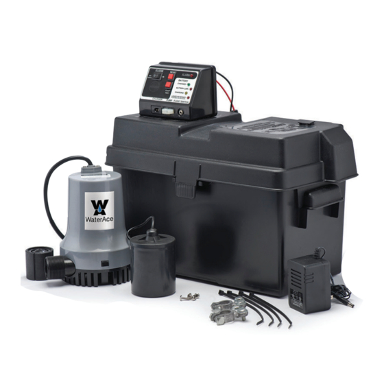
12 Volt Battery Backup
Sump Pump System
TABLE OF CONTENTS
General Safety . . . . . . . . . . . . . . . . . 2 & 3
Contents & Tools. . . . . . . . . . . . . . . . . . . 4
Installation. . . . . . . . . . . . . . . . . . . . 4 & 6
Parts. . . . . . . . . . . . . . . . . . . . . . . . . . . . 5
Testing & Operation . . . . . . . . . . . . . . . . 7
Warranty. . . . . . . . . . . . . . . . . . . . . . . . . 8
Advertisement
Table of Contents

Related Manuals for Eco-Flo Water Ace WASBB


Summary of Contents for Eco-Flo Water Ace WASBB
- Page 1 Owner’s Manual 12 Volt Battery Backup Sump Pump System TABLE OF CONTENTS General Safety ....2 & 3 Contents & Tools....4 Installation.
- Page 2 STOP Before you start A sump pump is an electrical device designed to operate in inherently wet environments. ALWAYS USE EXTREME CAUTION when installing or maintaining this product! Need Help: Call 1-844-394-2604 for assistance; Do Not Return to Store GENERAL SAFETY Important Safety Instructions General Safety Carefully read and follow all safety...
- Page 3 Provide proper ventilation. The battery enclo- 2. Do not open or mutilate the battery. Released sures should be designed to prevent accumu- electrolyte is harmful to the skin and eyes. It lation and concentration by hydrogen gas in may be toxic. “pockets”...
- Page 4 CONTENTS 2 - Wire ties 1 - 12 volt battery backup sump pump 1 - Plastic battery case (Battery not included) 1 - Control/alarm panel 1 - Dual pipe size (1-1/2” or 1-1/4”) PVC tee 1 - Float switch with a 1” threaded check valve fitting for 1 - 12 volt battery charger installing the pump 1 - Extra fuse...
- Page 5 INSTALLATION STEP 3: Thread the Battery Backup Sump Pump onto thedual size pipe tee provided. Once the pump is threaded tight and oriented parallel to the discharge pipe, turn the pipe to the 2 o’clock position to prevent air from being trapped in the pump housing. Then cement the installation tee to the discharge pipe with PVC primer and PVC cement.
- Page 6 BATTERY & CONTROL/ALARM PANEL ASSEMBLY STEP 6: Feed the pump and float switch cords through the sump pump vent or utility hole and cover the sump with the sump cover. Power Cord Float Switch Cord STEP 1: Pre-drilled Mount the Control/Alarm Panel to the battery case Mounting Holes using the four mounting screws provided.
- Page 7 TESTING THE SYSTEM STEP 1: Disconnect the power to the primary sump pump so the only pump available is the Battery Backup Sump Pump. STEP 2: With a garden hose or buckets of water fill the sump basin with water. At the designated level of water, the Bat- tery Backup Sump Pump should activate and the ALARM and ALARM INDICATOR LIGHT should come on.
- Page 8 WARRANTY Retain Original Purchase Receipt for Warranty Eligibility Limited Warranty Manufacturer warrants to the original consumer purchaser (“Purchaser” or “You”) that its products are free from defects in material and workmanship for a period of twelve (12) months from the date of the original consumer purchase. If, within twelve (12) months from the original consumer purchase, any such product shall prove to be defective, it shall be repaired or replaced at manufacturer’s option, subject to the terms and conditions set forth herein.
Need help?
Do you have a question about the Water Ace WASBB and is the answer not in the manual?
Questions and answers