PS Engineering PM3000 Installation And Operation Manual
High-fidelity stereo 6-place intercom system
Hide thumbs
Also See for PM3000:
- Pilot's manual (9 pages) ,
- Operation and installation manual (13 pages)
Table of Contents
Advertisement
Quick Links
9800 Martel Road
Lenoir City, TN 37772
PM3000
High-fidelity Stereo 6-place Intercom System
Operation and Installation Manual
Document P/N 200-193-0000
Revision 0 May 1998
PS Engineering, Inc. 1998 ©
Copyright Notice
Any reproduction or retransmittal of this publication, or any portion thereof, without the expressed written permission of PS
Engineering, Inc. is strictly prohibited. For further information contact the Publications Manager at PS Engineering, Inc., 9800
Martel Road, Lenoir City, TN 37772. Phone (423) 988-9800
Advertisement
Table of Contents

Related Manuals for PS Engineering PM3000


Summary of Contents for PS Engineering PM3000
- Page 1 Any reproduction or retransmittal of this publication, or any portion thereof, without the expressed written permission of PS Engineering, Inc. is strictly prohibited. For further information contact the Publications Manager at PS Engineering, Inc., 9800 Martel Road, Lenoir City, TN 37772. Phone (423) 988-9800...
-
Page 2: Table Of Contents
PS Engineering Incorporated PM3000 Installation and Operation Manual Table of Contents 1. SECTION I GENERAL INFORMATION NTRODUCTION COPE ESCRIPTION PPROVAL ASIS PECIFICATIONS QUIPMENT REQUIRED BUT NOT SUPPLIED ICENSE EQUIREMENTS 2 SECTION II INSTALLATION ENERAL NFORMATION NPACKING AND PRELIMINARY INSPECTION QUIPMENT INSTALLATION PROCEDURES ABLE HARNESS WIRING 2.4.1... -
Page 3: Section I General Informationi
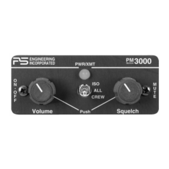
With few controls for the pilot to use, the operation of the PM3000 is very straightforward. Yet the unit outperforms its much more complicated competition. Although there is only one volume control knob, when an adjustment is made to the volume control, many output amplifiers are being changed simultaneously. -
Page 4: Approval Basis
RTCA DO-160C/DO-214 Temperature -20º to +55ºC Equipment required but not supplied A. Interconnecting cables as required (may be ordered from PS Engineering) B. Headphones, 150 stereo, up to six as required C. Microphones, up to six, as required D. Interconnect wiring E. -
Page 5: Section Ii Installation
Section II Installation General Information The PM3000 comes with all mounting hardware and jacks for installation. Installation of the PM3000, using the hardware supplied and available wiring does not require special tools or knowledge other than described in FAA Advisory Circular 43.13-2. It is the installer's responsibility to determine the approval basis for this installation. -
Page 6: Cable Harness Wiring
To connect intercom into the aircraft audio system, parallel the appropriate set of cables from the intercom to the Auxiliary Aircraft Radio Headset Jacks. Finally, install new headset jacks into the aircraft and connect them directly to the appropriate pins of the PM3000. See the wiring diagram for all details of the wire harness interconnect. -
Page 7: Power Requirements
PM3000 Installation and Operation Manual 2.4.2 Power Requirements The PM3000 was designed to work with 12.8 to 27.5 volt DC negative ground systems. The PM3000 must be externally protected with a one ampere (1A) circuit breaker or fuse. 2.4.3 Sidetone The PM3000 can be modified to produce sidetone (hearing your voice during transmit), if the aircraft radios do not produce it. -
Page 8: Post Installation Checkout
1. Apply power to the aircraft and avionics. 2. Plug headsets into the pilot, copilot and passenger positions. 3. Verify that the pilot position can transmit and receive with the PM3000 in the OFF position (left hand knob controls on/off). -
Page 9: Section Iii Operation
Regardless of configuration, the pilot will always hear the aircraft radio. NOTE: If there is a power failure to the PM3000, or if the power switch is turned off, the copilot will not hear the aircraft radio. Only the pilot is connected directly to the aircraft radio. -
Page 10: Section 4 Warranty And Serviceb
In order for the factory warranty to be valid, the installations in a certified aircraft must be accomplished by an FAA- certified avionics shop and authorized PS Engineering dealer. If the unit is being installed by a non-certified individual in an experimental aircraft, a factory-made harness must be used for the warranty to be valid. -
Page 11: Appendix A - Ptt Modificationsc
(Airframe, Powerplant, Propeller, or Appliance) In the case of the PMA3000, 11930, you may use the following text as a guide. Installed 6-place intercom, PS Engineering PM3000, part number 11930 in ( location ) at station . Installed per AC43.13-2, Chapter 2, paragraph 23 (Instrument Panel Mounting). - Page 12 Installation and Operation Manual Aircraft equipment list, weight and balance amended. Compass compensation checked. A copy of the operation instructions, contained in PS Engineering document 200-193-0000, revision 0, May 1998, is placed in the aircraft records. All work accomplished listed on Work Order...
-
Page 13: Appendix C, Instructions For Continuing Airworthiness
Installation and Operation Manual Appendix C, Instructions for continuing airworthiness The PM3000 is considered an “on-condition” maintenance item. It is checked prior to each flight during normal operation. There are no additional considerations for continuing airworthiness other than the practices detailed in AC 43.13-1A, Chapter 15, Paragraph 750. This includes inspecting the unit to be sure it is securely fastened in its location, and that the wiring harness is not chafed or pinched, and remains secure. -
Page 14: Appendix D Wiring Diagram
PS Engineering Incorporated PM3000 Installation and Operation Manual Appendix D Wiring Diagram PM3000 Sub-D DB- 25 Male 11-33 VDC Power In Ground T o A irc raf t R adi o P hon e Au dio Hi A/C Radio Phone Audio Hi...
Need help?
Do you have a question about the PM3000 and is the answer not in the manual?
Questions and answers