Table of Contents
Advertisement
INSTRUCTIONS FOR USE
AND MAINTENANCE OF THE
8-28 KG WASHING MACHINE
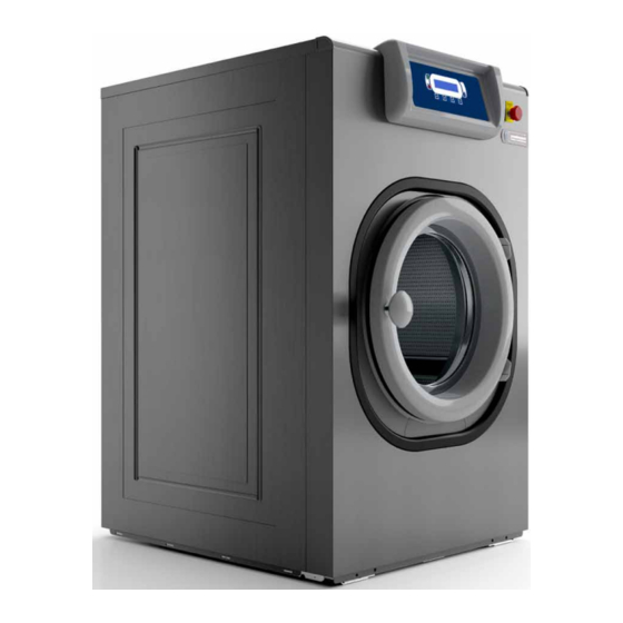
WASHING MACHINE series GWM - GWN - GWH
Edition 01.2015
TRANSLATION OF ORIGINAL INSTRUCTIONS
via Masiere 211/c - 32037 - Sospirolo (BL) - Italy
Tel. +39 (0) 437 848 711 Fax +39 (0) 437 879 108
e-mail: info@grandimpianti.com web: www.grandimpianti.com
Advertisement
Table of Contents

Related Manuals for grandimpianti GWM Series


Summary of Contents for grandimpianti GWM Series
- Page 1 WASHING MACHINE series GWM - GWN - GWH Edition 01.2015 TRANSLATION OF ORIGINAL INSTRUCTIONS via Masiere 211/c - 32037 - Sospirolo (BL) - Italy Tel. +39 (0) 437 848 711 Fax +39 (0) 437 879 108 e-mail: info@grandimpianti.com web: www.grandimpianti.com...
- Page 2 It is essential to train the personnel in charge of running, performing maintenance, and inspecting the machine in compliance with the operating procedures and safety standards indicated in these user manual. Remember that the Manufacturer, in any case, is always available to provide clarifications or further information. INDEX OF REVISIONS Version Revision Date 01.2015 COPYRIGHT © 2015 GRANDIMPIANTI S.p.A.
-
Page 3: Table Of Contents
TABLE OF CONTENTS MACHINE IDENTIFICATION ........................5 MANUFACTURER IDENTIFICATION ......................5 SUPPLIER IDENTIFICATION ........................6 DISTRIBUTOR IDENTIFICATION ........................6 MACHINE VERSIONS ..........................7 IDENTIFICATION PLATE ..........................8 DECLARATION OF CONFORMITY (copy).....................9 WARRANTY ..............................10 RECIPIENTS ..............................11 SUPPLY AND STORAGE ..........................11 UPDATES ..............................11 LANGUAGE ..............................11 SYMBOLS USED IN THE MANUAL ......................12 GLOSSARY OF THE TERMS USED ......................13 RELEVANT DIRECTIVES ..........................14 DEFINING THE OPERATOR QUALIFICATIONS ....................15... - Page 4 WASHING MACHINE Series GWH / GWM / GWN INSTALLATION............................42 PERMISSIBLE AMBIENT CONDITIONS ........................... 42 INSTALLATION AND POSITIONING SITE ........................42 SECURING ..................................46 ADJUSTMENTS ............................48 IMBALANCE MICRO SWITCH ADJUSTMENT (GWH model only) ..................48 CONNECTIONS ............................49 WATER CONNECTION ..............................49 DRAIN PIPE CONNECTION ............................
-
Page 5: Machine Identification
GWH / GWM / GWN Year of manufacture 2015 Serial number MANUFACTURER IDENTIFICATION Name GRANDIMPIANTI ILE ALI S.p.A. via Masiere 211/c 32037 - Sospirolo (BL) - Italy Tel. +39 (0) 437 848 711 Address Fax +39 (0) 437 879 108 e-mail: info@grandimpianti.com... -
Page 6: Supplier Identification
WASHING MACHINE Series GWH / GWM / GWN SUPPLIER IDENTIFICATION Supplier (importer) Importer stamp DISTRIBUTOR IDENTIFICATION Distributor Distributor stamp... -
Page 7: Machine Versions
Column 6 Column 7 Char. 1 Char. 2 Char. 3 Char. 4-5-6 Char. 7 Char. 8 Char. Extra COIN Key: Grandimpianti Column 1 = Manufacturer Technolaundry Washing machine Dryer Column 2 = Type of machine Ironer Barrier High spin Factor G400... -
Page 8: Identification Plate
WASHING MACHINE Series GWH / GWM / GWN IDENTIFICATION PLATE The CE plate bearing the identification data and CE mark is permanently attached on the rear side of the appliance. A plate bearing the identification data and the weight of the appliance is also applied to the packaging. IMPORTANT! Check that the model of the appliance specified on the identification plate and on the packaging plate is the same as that stated on the transport document or invoice. -
Page 9: Declaration Of Conformity (Copy)
DECLARATION OF CONFORMITY (copy) -
Page 10: Warranty
WASHING MACHINE Series GWH / GWM / GWN WARRANTY The warranty covers a period of twelve months, from the date of purchase of the appliance or of an integral part thereof. The warranty consists in replacing any failed parts for ascertained manufacturing causes and it is applied directly by your supplier. The workforce along with shipping and packaging costs as well as transport risks shall always be borne by the purchaser. -
Page 11: Recipients
DESCRIPTION OF THE MANUAL RECIPIENTS The instructions for use and maintenance are designed for the people in charge of using and managing the appliance and the technician enabled to perform installation and maintenance procedures. Here, reference is made to a correct use of the appliance, with a veiw to maintaining the functional characteristics and quality thereof unchanged over time. -
Page 12: Symbols Used In The Manual
WASHING MACHINE Series GWH / GWM / GWN SYMBOLS USED IN THE MANUAL Below is a list of symbols used in this manual: Symbol Description Refer to the manual/instruction booklet. Mandatory action general signal. General warning signal. Explosion hazard warning signal. Electrical hazard warning signal. -
Page 13: Glossary Of The Terms Used
GLOSSARY OF THE TERMS USED To facilitate the understanding of the manual, the following are some definitions of the terms used. Term Definition SOAKING Phase of the washing cycle that helps loosen dirt or stains that are difficult to remove. APPLIANCE Product covered by the manual. -
Page 14: Relevant Directives
WASHING MACHINE Series GWH / GWM / GWN GENERAL INFORMATION RELEVANT DIRECTIVES For the appliance design, construction and installation, the following directives and standards have been referred to: 2006/42/CE MACHINE DIRECTIVE 2004/108/EC ELECTRO MAGNETIC COMPATIBILITY DIRECTIVE 2006/95/EC LOW VOLTAGE DIRECTIVE... -
Page 15: Defining The Operator Qualifications
DEFINING THE OPERATOR QUALIFICATIONS Operators are people responsible for the installation, operation, adjustment, and implementation of the appliance routine maintenance and cleaning (each within the limits of the tasks assigned). They are classified as: Term Definition Person adequately advised or supervised by a trained person in such a way as to be able INFORMED PERSON to perceive risks and prevent dangers potentially posed by the appliance operation or maintenance. - Page 16 WASHING MACHINE Series GWH / GWM / GWN WARNING! The appliance can be used by children and people with reduced physical, sensory or mental capabilities, or lack of experience or necessary knowledge, provided they are supervised or have received instructions for the safe use of the appliance and understand the dangers associated with it.
- Page 17 WARNING! Any installation changes must be approved by the Manufacturer. Otherwise, the manufacturer will not be responsible for any damage to the appliance and/or injury to operators. WARNING! The drum of the washing machine may contain residues of products used during the production process.
- Page 18 WASHING MACHINE Series GWH / GWM / GWN WARNING! If the appliance is not in use for two or more weeks, hydrogen may form inside it, i.e. in the hot water system. Hydrogen gas is explosive. Open the taps and let the hot water run for a few minutes before using the appliance.
- Page 19 WARNING! In the case in which the appliance operates in self-service laundries, an emergency stop device must be installed inside the laundry room. The emergency stop device must be positioned in a visible place, accessible to all users. For installation, please refer to standard EN10472-1. According to it, the "Manufacturer/Installer" must ensure that there are enough devices so that at least one is visible from any location within the operator access area, 2 m away from the machine, and that each device must be located within 8 m from the operator workstations.
-
Page 20: Obligations
WASHING MACHINE Series GWH / GWM / GWN OBLIGATIONS • Only allow properly trained personnel to operate on the appliance. • Do not use the appliance improperly, i.e. for uses other than those specified in the "Intended Use" paragraph. • Do not allow the appliance to be used by children, people with limited physical and mental abilities, and/or personnel not yet trained, without proper supervision. -
Page 21: Residual Risks
RESIDUAL RISKS Safety has been integrated, as far as possible, in the appliance design and construction. Therefore, the operators must be protected against residual risks especially during maintenance, installation, and cleaning operations. Residual risk Provision Picture Do not place hands or objects in the tube RISK OF SHEARING connecting the tank to the dispenser or in the AND BURNING... - Page 22 WASHING MACHINE Series GWH / GWM / GWN Residual risk Provision Picture Risk of burning Do not open the appliance dispenser door nor position your hands near the air-break RISK OF BURNING/ device, as steam or irritating sprays of hot SCALDING liquid may come out of it.
-
Page 23: Symbols Applied To The Appliance
Residual risk Provision Picture Pay special attention not to mix detergents, soaps, or other chemical substances used to remove dirt from the treated fabric in the RISK OF same washing bath or in the intake pipes. POISONING In fact, chemical reactions may result from AND INTOXICATION reagents capable of developing dangerous liquids or gases for human health or capable... - Page 24 WASHING MACHINE Series GWH / GWM / GWN Symbol Description Attention, electric hazard. Disconnect the appliance from the mains before any intervention. Equipotential connection. Burn injury hazard. Attention, dangerous voltage hazard. Capacity of the fuses on the appliance. Enabling the programming of no. tokens in the appliances required for self-service operation. Steam supply input.
- Page 25 Symbol Description Entanglement and cutting hazard due to rotating parts, and prohibition to operate with moving parts. USB port. Attention, electric hazard. Disconnect the appliance from the mains before any intervention. Do not tread. Crushing hazard. Advice for the installation and the wire section of the power supply wires. Power supply disconnector device on the machine.
-
Page 26: Intended Use
WASHING MACHINE Series GWH / GWM / GWN GENERAL DESCRIPTION INTENDED USE The appliance concerned is intended for industrial use: Operation Allowed Forbidden Processing environment Industrial laundries, • Fabrics soaked with self-service laundries, condo Fabrics flammable substances, laundries WASHING of: solvents, acids, grease. -
Page 27: Noise
• Use in environments subject to atmospheric agents (and system exposure to lightning, and brackish or salty environments). • Use in environments with a high risk of fire and/or explosion. • Use in environments subject to electromagnetic disturbances. WARNING! The use of the appliance for performance other than that specified, is considered "improper use". Any other use needs prior authorisation in writing by the Manufacturer. -
Page 28: General Description
WASHING MACHINE Series GWH / GWM / GWN GENERAL DESCRIPTION The appliance structure consists of: • A moving part, including the steel drum, mechanical transmission with pulley system, motor, springs, shock absorbers (springs and shock absorbers are only available in the GWH version). •... -
Page 29: Main Components
MAIN COMPONENTS The appliance consists of: Pos. Element Detergent dispenser Control panel Side panels Laundry loading/unloading porthole Mixer Frame Pulley Drum unit and tank Electric motor Transmission belt Emergency button Drain Disconnector... -
Page 30: Technical Data
WASHING MACHINE Series GWH / GWM / GWN TECHNICAL DATA GWH GENERAL DATA Characteristics kg 8 kg 11 kg 14 kg 18 kg 24 kg 28 Load ratio 1:10 kg/ 4 ÷ 8 5.3 ÷ 10.5 6.75 ÷ 13.5 9 ÷ 18 12 ÷... - Page 31 Characteristics kg 8 kg 11 kg 14 kg 18 kg 24 kg 28 220-240V 1~50/60 Hz 230-240V 3~50/60 Hz Power supply 380-415V 3N~50/60 Hz 440-480V 3~60 Hz Net/gross weight (kg) 135/145 170/185 190/200 255/270 275/290 290/305 Dynamic floor load 1.6± 2.4 1.9 ±...
-
Page 32: Gwh Dimensions
WASHING MACHINE Series GWH / GWM / GWN GWH DIMENSIONS kg 8 kg 11 kg 14 kg 18 kg 24 kg 28 A (mm) 1140 1250 1250 1455 1455 1455 B (mm) 1090 C (mm) D (mm) E (mm) F (mm) G (mm) J (mm) K (mm) - Page 33 kg 8 kg 11 kg 14 kg 18 kg 24 kg 28 N (mm) P (mm) R (mm) 1100 1100 1270 1270 1270 S (mm) 1060 1155 1155 1310 1310 1320 T (mm) 1060 1170 1170 1350 1360 1360 U (mm) V (mm) W (mm) X (mm)
-
Page 34: Gwm / Gwn Dimensions
WASHING MACHINE Series GWH / GWM / GWN GWM / GWN DIMENSIONS... - Page 35 kg 8 kg 11 kg 14 kg 18 kg 24 kg 28 A (mm) Width B (mm) Height 1120 1230 1230 1440 1440 1440 C (mm) D (mm) 1086 E (mm) F (mm) G (mm) H (mm) I (mm) 1035 1148 1148 1336...
-
Page 36: Safety Devices
WASHING MACHINE Series GWH / GWM / GWN SAFETY DEVICES The appliance has been designed and provided with a safety data sheet to minimise risks for the user. The safety data sheet installed on the appliance allows you to make checks on: Element Pressure switch water level Emergency stop... -
Page 37: Safety Warnings For Transport
TRANSPORT SAFETY WARNINGS FOR TRANSPORT IMPORTANT! After receiving the appliance, check the condition of the packaging. In case of visible damage, remove the packaging in the presence of the carrier and sign the transport document with reservation. WARNING! The manufacturer is not liable for any material damage or personal injury due to accidents caused by failure to comply with the instructions in this manual. -
Page 38: Table Of Dimensions And Weights (For Transport)
WASHING MACHINE Series GWH / GWM / GWN TABLE OF DIMENSIONS AND WEIGHTS (FOR TRANSPORT) Model Gross weight Width * Depth * Height * Min. fork length kg 8 205 kg 810 mm 880 mm 1280 mm 1100 mm kg 11 240 kg 895 mm 880 mm... -
Page 39: Transport With Transpallet
TRANSPORT WITH TRANSPALLET WARNING! The transport and handling activities described in this section must be performed by qualified personnel with specific skills for such operations. WARNING! Refer to the "Technical data" section for the weight of the appliance. The appliance is transported to the point closest to the installation lsite on a pallet by means of a transpallet. Observe the minimum fork length specified in the section "TABLE OF DIMENSIONS AND WEIGHT FOR TRANSPORT". -
Page 40: Unpacking
WASHING MACHINE Series GWH / GWM / GWN WARNING! Do not lift the appliance without first anchoring it to a pallet. WARNING! Any damage caused by handling the machine in a different way from that described in this manual shall not be attributed to the Manufacturer. UNPACKING IMPORTANT! After delivering the appliance, check the condition of the packaging. -
Page 41: Storage
STORAGE The product must be stored in a closed environment, protected from the elements. The minimum and maximum conditions for the appliance storage are listed below. Model Room temperature (°C) Room relative humidity (%) All models without condensation without condensation If the appliance is not used for a period exceeding one month, please observe the following: Step Element... -
Page 42: Installation
WASHING MACHINE Series GWH / GWM / GWN INSTALLATION, CONNECTIONS, AND ADJUSTMENTS INSTALLATION WARNING! Installation must be carried out by a qualified installer trained by the Manufacturer, in the presence of an electrical technician able to make the electrical connections required. WARNING! Any installation changes must be approved by the Manufacturer. - Page 43 Model 522 mm 474 mm 69 mm 139 mm 57.5 mm 660 mm 670.5 mm kg 8 20.55 inch 18.66 inch 2.71 inch 5.47 inch 2.26 inch 25.98 inch 26.39 inch 615 mm 474 mm 67.5 mm 139 mm 57.5 mm 750 mm 670.5 mm kg 11...
- Page 44 WASHING MACHINE Series GWH / GWM / GWN min 50 min 50 min 50 min 50 Note: For the reference points in the figures, refer to paragraph “DIMENSIONS”. Place the appliance near the discharge on the floor or near the discharge channel. To allow installation and support interventions, comply with the recommended distances:...
- Page 45 • at least 500 mm of free space between the appliance and the rear wall; • at least 50 mm of free space between appliance side and side wall or other appliance. Moreover, check that: • the electric absorption of the appliance is lower than that supplied by the electric company; •...
-
Page 46: Securing
WASHING MACHINE Series GWH / GWM / GWN SECURING To secure the appliance, perform the operations described below. After locating the appliance in the place of installation, proceed to remove the appliance upper, front, rear, central and lower panels (the latter only in some models where fixings are less accessible): Step Action Unscrew the two M6 Torx head rear screws to remove the top panel. - Page 47 Then proceed to secure the device to the floor (or metal base, only for GWM/GWN) models, as described below: Step Action Place the appliance on the drilled holes. Make sure the appliance has a steady, horizontal position in all corners. If this is not the case, balance the appliance by inserting stainless steel supports or “A”...
-
Page 48: Adjustments
WASHING MACHINE Series GWH / GWM / GWN ADJUSTMENTS WARNING! Adjustment operations must be performed by a certified technician who has been trained by the Manufacturer. IMBALANCE MICRO SWITCH ADJUSTMENT (GWH model only) Adjust the imbalance micro switch to prevent excessive imbalances of the tank drum unit during spinning, and ensure proper operation of the appliance. -
Page 49: Connections
CONNECTIONS WARNING! The connections to the appliance must be carried out by a qualified installer trained by the manufacturer, in the presence of an electrical technician able to make the electrical connections required. WARNING! The Manufacturer will not be responsible for any damage to the appliance caused by faulty connections, or use of connection materials other than those described. - Page 50 WASHING MACHINE Series GWH / GWM / GWN Water hardness can be determined using the table below: °fH (French English Classification mmol/dm °dH (German degrees) degrees) degrees 0 → 1.25 0 → 7 0 → 12 0 → 8.75 Soft 1.25 →...
-
Page 51: Drain Pipe Connection
DRAIN PIPE CONNECTION The appliance is equipped with a connector for the drain pipe (A) of the water used during the washing process. For the drain pipe connection, the Manufacturer provides the following: • A 3” rubber elbow • two metal strips to connect the drain. Model Drain pipe kg 8... - Page 52 WASHING MACHINE Series GWH / GWM / GWN Some special versions are equipped with a drain to recover the water of some washing phases. WARNING! Make sure that the distance between the appliance drain connector and the floor drain is not greater than the supplied elbow-joint length.
-
Page 53: Steam And Condensate Connection (Only For Appliances With Steam Heating)
STEAM AND CONDENSATE CONNECTION (ONLY FOR APPLIANCES WITH STEAM HEATING) Incoming steam Model Inlet size Steam type pressure All models with 50 KPa ÷ 600 KPa M 3/4" threaded dry saturated steam heating Provide for a valve to disconnect the appliance in case of maintenance or failure. Insert the supplied filter with F/F 3/4”... - Page 54 WASHING MACHINE Series GWH / GWM / GWN Step Action Connect to the clamp on the side of the disconnector switch protected by the rear cover of the electrical panel. Note: Use the cable gland mounted on the rear panel. WARNING! Should multiple appliances be installed in the same room, ensure that a protective equipotential connection is made between all appliances, using the outer protective clamp on the rear of the...
- Page 55 POWER SUPPLY CONNECTION Below is the connection diagram of the appliance to the electrical mains (with differential switch): Pos. Element Description • Operating current = 100mA (if it is not allowed in the installation site, use 30mA current, and choose the minimum delay type).
- Page 56 WASHING MACHINE Series GWH / GWM / GWN WARNING! The power supply cable is not part of the supply. The power supply cable must be: • Conducting with copper nuclei • Flexible • Short and straight from the power protection device to the appliance, without deviation •...
- Page 57 POWER SUPPLY CABLE CONDUCTOR ENDS Pos. Element Protective conductor Phase conductor Phase conductor Phase conductor Neutral conductor Tube terminal Stripped conductor length MAIN SUPPLY CONNECTION Pos. Element Master switch Loop Power supply cable loosening To make the power supply connection, follow this procedure: Step Action Insert the cable into the hole on the rear panel.
- Page 58 WASHING MACHINE Series GWH / GWM / GWN Step Action Leave the (PE) protective earth conductor slightly longer. Note: So that it disconnects last in case of accidental detachment of the cable. For stripped conductor ends, use isolated pins for L1/U, L2/V, L3/W, N. Note: Make sure no accidental contact is possible as the power supply cable remains live even if the master switch is turned off.
-
Page 59: Liquid Detergent Introduction Pump Connection (Optional)
LIQUID DETERGENT INTRODUCTION PUMP CONNECTION (OPTIONAL) WARNING! The appliance connections must be carried out by a qualified installer, trained by the Manufacturer. In the back of the device there are 13 inputs (1) for the hydraulic connection of the liquid detergent automatic dispensing system. Three different diameters are available to allow the connection of the different sections of pipes that can be provided with the automatic dispensing systems. -
Page 60: Electrical Connection Of The Liquid Detergent Automatic Dispensing System
WASHING MACHINE Series GWH / GWM / GWN ELECTRICAL CONNECTION OF THE LIQUID DETERGENT AUTOMATIC DISPENSING SYSTEM WARNING! The appliance electrical connections must be performed by a qualified, enabled technician. Refer to the wiring diagram for connection modes. For the electrical connection of the signals controlling the dispensing system, a terminal block for the corresponding pump connection is provided on the back of the appliance. -
Page 61: Testing
TESTING Functional testing, designed to check the appliance for proper operation, is carried out at the factory. On-site, during installation, a technician must check that the machine is properly installed. This means checking: • Floor anchors • Transport damage • Levelling •... -
Page 62: Safety Instructions For Maintenance
WASHING MACHINE Series GWH / GWM / GWN MAINTENANCE SAFETY INSTRUCTIONS FOR MAINTENANCE The appliances must undergo regular technical maintenance, and any detected defect which can jeopardise the workers' health and safety must be eliminated immediately. WARNING! Maintenance operations must be performed by qualified, authorised personnel. From an operational point of view, maintenance operations can be divided in two main categories: Routine All those preventive operations that the operator must carry out to ensure the smooth operation of... -
Page 63: Routine Maintenance
ROUTINE MAINTENANCE To ensure the appliance proper operation, regular and preventive checks and maintenance work must be carried out according to the tables provided and the maintenance schedule indicated therein. Failure to observe the above exempts the Manufacturer from any liability to the effects of the warranty. The intervals indicated refer to normal operating conditions, i.e. -
Page 64: Operations To Be Performed Every 1000 Cycles
WASHING MACHINE Series GWH / GWM / GWN OPERATIONS TO BE PERFORMED EVERY 1000 CYCLES Required IPD Operator qualification Required equipment • Key kit USER • Screwdriver • Torx The appliance electronic control counts its cycles and operating hours. Every 1000 cycles (or manually), it indicates the request for maintenance. Proceed as follows as soon as the message is displayed: Pos. -
Page 65: Cleaning
Freestanding machines: 14 kg / 30 lb 79 - 83 Hz 18 kg / 40 lb 64 - 69 Hz 24 - 28 kg / 55 - 65 lb 72 - 75 Hz Rigid-mount machines: 8 kg / 18 lb 88 - 98 Hz 11 kg / 25 lb 62 - 67 Hz... - Page 66 WASHING MACHINE Series GWH / GWM / GWN DISPLAY CLEANING. Required IPD Operator qualification Required equipment USER • Damp cloth To clean the display, use a slightly damp cloth without exerting too much pressure. Part of the display consists of a fluid. WARNING! Breaking the display can cause fluid leakage.
- Page 67 SOFTENER SYPHON CLEANING Required IPD Operator qualification Required equipment USER • Screwdriver To clean the softener syphon, proceed as described: Pos. Element Picture Open the dispenser lid. Remove the water nozzle deflector (pulling upwards). Remove the softener pan. Remove the softener syphon and rinse it with running water.
-
Page 68: Extraordinary Maintenance
WASHING MACHINE Series GWH / GWM / GWN EXTRAORDINARY MAINTENANCE WARNING! Extraordinary maintenance operations are reserved for qualified, technical employees, trained and authorised by the Manufacturer or the Authorised After-Sales Centre. These interventions require in-depth, specific knowledge of the appliance as well as the operations required, associated risks and correct procedures for safe operation. -
Page 69: Replacing The Door Gasket
REPLACING THE DOOR GASKET Required IPD Operator qualification Required equipment • Rope ENABLED TECHNICIAN • Silicone To replace the door gasket, proceed as follows: Step Action Open the door. Remove the glass of the door with the gasket, pulling the gasket of the door steel frame in the drum direction. Tear off the gasket from the glass. -
Page 70: Replacing Fuses
WASHING MACHINE Series GWH / GWM / GWN REPLACING FUSES Required IPD Operator qualification Required equipment ENABLED TECHNICIAN WARNING! Make sure the appliance is not connected to the power supply and cannot be accidentally turned on. The fuse precise values can be found close to the fuse casings and in the circuit diagram supplied with the appliance. If a fuse blows, it can be replaced with a fuse with the same value, but never with a fuse having a higher value. -
Page 71: Decommissioning
DECOMMISSIONING DECOMMISSIONING To decommission the appliance, proceed as described: Pos. Element Disconnect the appliance external power supply. Disconnect the appliance main switch. Close the water and steam supply (if any) and disconnect the pipes. Unscrew the floor fixing screws. Remove the machine following the transport procedures described in this manual. Remove the appliance door to prevent the appliance from being re-commissioned. -
Page 72: Disposal
WASHING MACHINE Series GWH / GWM / GWN DISPOSAL IMPORTANT! In compliance with the standards for waste disposal in force in the installation country, and with a view to safeguarding the environment in which the appliance is installed, all appliance parts must be divided so as to be properly disposed of and recovered. -
Page 73: Troubleshooting
RICERCA GUASTI TROUBLESHOOTING The following information is intended to assist you in identifying faults and restore the appliance functionality and efficiency. MALFUNCTIONS OR FAULT MESSAGES IMPORTANT! To search for "possible causes" and "remedies", refer to the tables contained in the following paragraphs. - Page 74 WASHING MACHINE Series GWH / GWM / GWN Malfunction or fault message Possible causes Remedy A 103 "Water drain too slow" 7,33,40,42,67,74,75,85,87,139 4,8,16,19,33,36,41,42,50 A 104 "Load Timeout" ,56,57,64,65,67,78 A 105 "Recirculation pump thermal protection" 53.135 A 106 ""Recirculation pump overtemperature protection" 53,135,136 A 107 "Empty recovery tank"...
- Page 75 Malfunction or fault message Possible causes Remedy E5 "Overtemperature or disconnected probe" 17,82,83,137 7,15,24,25,30,32,33,36,3 E6 "Failure to lock/unlock" 8,52,140,142 7,11,15,24,25,30,32,33,3 E7 "Door fault" 6,38,52,55 E8 "Level fault" 14,67,71,72,81,88,90,96,141 E9 "Imbalance" 14,35,60,61,85,86,114 Machine malfunctions 12,13,14,16,17,24,26,27, The cycle does not start 28,30,48,55 The cycle is not performed properly 12,13,14,35,52,53,56 12,13,24,26,27,28,29,41...
- Page 76 WASHING MACHINE Series GWH / GWM / GWN Malfunction or fault message Possible causes Remedy The machine produces splashes from the soap dispenser 70,79,80 Powder is not loaded in the machine from the dispenser 70.78 The water level drops during the cycle and the machine tops it up 68,71,72 Inconsistency between displayed value and real level in the tank 71,72,96...
-
Page 77: Possible Causes
Malfunction or fault message Possible causes Remedy Burnt motor 6,14,54,67,130 Burnt transformer 54.120 24V - 10A fuse burnt "ESAF" flashes on the inverter "SA" flashes on the inverter 4,45,67,122,123,124 POSSIBLE CAUSES Possible causes No power supply / plug disconnected or faulty Disconnector in the OFF position or faulty Appliance fuses actuated or not present Board connectors disconnected... - Page 78 WASHING MACHINE Series GWH / GWM / GWN Misalignment Broken handle spring Burnt power supply 24V fuse Lack of all necessary signals Failed/incomplete inverter programming Disconnected flat cable Damaged lock cable Burnt lock coil Discontinued resistors Faulty contactor Relay board fault Faulty cable Loose belt Belt is broken or out of the pulley...
- Page 79 Damaged/perforated pressure switch Air loss in the pressure switch circuit Correct weighing level Burnt discharge valve Jammed/dirty discharge valve Water leak Faulty valves Low water pressure Excessively high water pressure No secondary flow limiter Jammed inlet valves Faulty temperature probe Wrong hot and cold water connection to the water mains Still drum during water loading Clogged drain...
-
Page 80: Remedies
WASHING MACHINE Series GWH / GWM / GWN Wrong TT-TNC-TNS configuration Faulty or disconnected imbalance micro switch Drum left in neutral from programming to final spin Odd or imbalanced load Breakage of tie rods fixing weights Noisy belt Resistors and their fixings loose Loose panels Collision between cables/pipes with the moving part 24V utility (valves, contactors, coils) in cc or overload...
Need help?
Do you have a question about the GWM Series and is the answer not in the manual?
Questions and answers