Table of Contents
Advertisement
Quick Links
Advertisement
Table of Contents

Summary of Contents for Toledo PWi Forging
- Page 1 PWi Forging Tonnage Monitor By Toledo Integrated Systems User’s Manual 17664...
- Page 3 PWi Forging User’s Manual PWi Forging User’s Manual Revision: A Doc #17663 Rev A Page Toledo Integrated Systems...
-
Page 4: Table Of Contents
Features Overview .......................... 6 Specifications ..........................7 Mounting the PWi Forging – Standard Installation ................ 9 Mounting the PWi Forging – Flush Mount Option ..............10 PWi Forging Components ......................11 Conduit Hole Selection ......................... 12 ... - Page 5 PWi Forging User’s Manual Threshold Menu ........................55 Learn Menu ..........................56 Delay Menu ..........................57 Offset Menu ..........................58 Mode Menu ..........................59 E-Stop Menu ..........................60 Setup Count Menu ........................61 ...
- Page 6 Table of Figures Figure 1.1: Standard Mounting Dimensions ..................9 Figure 1.2: Flush Mount Mounting Dimensions ................10 Figure 1.3: PWi Forging Components ................... 11 Figure 1.4: Conduit Hole Selection ....................12 Figure 1.5: AC Power Connection and Jumper Settings ............... 13 Figure 1.6: DC Power Connection ....................
-
Page 7: Installation
Installation Limited Warranty This unit is warranted by the manufacturer, Toledo Transducers, Inc., to be free of defects in workmanship and materials for one year from date of manufacturer’s shipment. This warranty is limited to repairing or replacing products which manufacturer’s investigation shows were defective at the time of shipment by the... -
Page 8: Features Overview
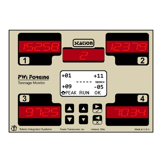
PWi Forging User’s Manual Features Overview The PWi Forging is a full-featured load monitor that interfaces with load sensors to provide force measurement for press protection and quality control. Unlike traditional tonnage monitors, the PWi Forging monitor is designed for the specific needs of forging applications. The total press load is displayed on high-visibility 7-segment LED displays for up to four forging stations. -
Page 9: Specifications
PWi Forging User’s Manual Specifications No. of Channels Four standard (Two optional) Load Input Sensor Inputs Full bridge strain gage sensors 120 to 1,000 ohms Up to (8) 350 ohm sensors Sensor Excitation Built-in 12VDC @ 300mA max (Short circuit protected) Sensor Input Connections 5-pin .15"... - Page 10 PWi Forging User’s Manual Supply Power Requirements 30 Watts max 85-132VAC @ 50-60Hz or (AC units) 170-264VAC @ 50-60Hz Power Input is jumper selectable Fuse 0.5A for 110VAC input 0.25A for 220VAC input TR5 type, Slow-Blow Requirements 24VDC @ 1.25A minimum...
-
Page 11: Mounting The Pwi Forging - Standard Installation
Failure to use these shock mounts may result in premature failure of the instrument and possibly void your warranty. The PWi Forging may be mounted directly to the press or to an adjacent structure. It should be positioned so that the display is easily read and the instrument is readily accessible. Figure 1.1 below provides the mounting dimensions and demonstrates the proper attachment of the provided shock mounts. -
Page 12: Mounting The Pwi Forging - Flush Mount Option
As with the standard installation, the flush mount option allows the PWi Forging to be mounted directly to the press or to an adjacent structure. It should be positioned so that the display is easily read and the instrument is readily accessible. -
Page 13: Pwi Forging Components
PWi Forging User’s Manual PWi Forging Components Analog Board Control Board Figure 1.3: PWi Forging Components Doc #17663 Rev A Page Toledo Integrated Systems... -
Page 14: Conduit Hole Selection
PWi Forging User’s Manual Conduit Hole Selection Follow Figure 1.4 to select the proper conduit hole for cabling. The holes are for ½" conduit, but they can be enlarged in the field if a larger fitting is required. BOTTOM VIEW... -
Page 15: Ac Power Connection And Configuration
Hole #3 (see Figure 1.4) for the AC Power Wiring. Use the proper fuse as indicated. With the proper jumper settings, the PWi Forging can be powered by either 110 VAC or 220 VAC (Factory set at 110 VAC.) The jumpers are located on the Analog Board as shown below. -
Page 16: Dc Power Connection
DC Power Connection (DC unit only) DC power is connected to the PWi Forging’s Analog Board as shown in Figure 1.6. The external 24VDC power supply should be rated at 1.25A or higher. Use Conduit Hole #3 (see Figure 1.4) for the DC Power Wiring. -
Page 17: Sensor Input Configuration
PWi Forging User’s Manual Sensor Input Configuration Each channel input on the PWi Forging Analog Board can be configured to accept a signal from a strain gage sensor, a 4-20 mA signal, or a 0-10 VDC signal. Balance and gain adjustments are made via two potentiometers for each channel. -
Page 18: Load Sensor Connection
Refer to Figure 1.8 for the procedures below to connect tonnage sensors properly: 1) Power down the unit. Open the door of the PWi Forging enclosure. 2) Run Load Sensor cables through Conduit Hole #1 (see Figure 1.4), and route cables upward to the Analog Board. -
Page 19: Sensor Cable Termination
PWi Forging User’s Manual Sensor Cable Termination 1) Strip the sensor cable as shown in the figure below. Be sure not to nick any of the signal conductors or cut the braid shield. Figure 1.9: Sensor Cable Stripping 2) Strip approximately ¼" of insulation from each of the four signal conductors. -
Page 20: Sensors Connection
PWi Forging User’s Manual Sensors Connection The PWi Forging accepts the signals from Toledo Transducers T-400 sensors as well as other strain gage sensors. Figure 1.10 illustrates the sensor connections. T400 Sensor T400 Sensor Tension Compression Force (Column-mounted sensor) (Pitman-mounted sensor) Tension connection shown. -
Page 21: Analog Output
PWi Forging User’s Manual Analog Output The analog outputs are provided on a 9-pin connector for easy access and for interfacing with other peripherals. BOTTOM VIEW Analog Voltage Output: Swing between 12V 1.25V @ Capacity Figure 1.11: Analog Output Wiring... -
Page 22: Probe Input
PWi Forging User’s Manual Probe Input The probe supply voltage (+12VDC) is supplied by the PWi Forging on the Vo terminal. The figure below shows the probe input location on the Analog Board and illustrates different wiring possibilities. Use Conduit Hole #2 (see Figure 1.4) to run the probe wiring. After wiring is completed, you must configure the unit for Probe triggering (see Page 54). -
Page 23: Figure 1.13: Probe Timing
PWi Forging User’s Manual The timing of the probe should be such that it turns on just before the machine begins generating a load, typically at (140) and remains on until the load is removed, typically at (240). Load Signal... -
Page 24: External Reset Switch Connection
PWi Forging User’s Manual External Reset Switch Connection Two terminals are provided for connecting an external reset switch. The rating of the switch and wiring can be minimal because they interface with a small signal. Use Conduit Hole #2 (see Figure 1.4) to run the wiring for the reset switch. -
Page 25: Serial Port Connection
PWi Forging User’s Manual Serial Port Connection An RS422 serial port is available for interfacing the PWi Forging with a computer running the PressNet software. RS422 allows the implementation of a daisy chain (multi-drop) serial network as a standard feature. -
Page 26: Figure 1.16: Rs232 Serial Port Wiring
PWi Forging User’s Manual Computer to single PWi Forging monitor wiring: Figure 1.16: RS232 Serial Port Wiring Computer to multiple PWi Forging monitors wiring (Networking): Figure 1.17: RS422 Serial Network Wiring Doc #17663 Rev A Page Toledo Integrated Systems... -
Page 27: Shutdown Relays
PWi Forging User’s Manual Shutdown Relays The PWi Forging provides a Top Stop Relay and an E-Stop (Emergency Stop) Relay. When enabled, the E-Stop Relay is used to stop the press immediately in case of a capacity violation. Each relay provides both Normally Open (N.O.) and Normally Close (N.C.) contacts. A toggle switch is provided to manually bypass the shutdown relays, if necessary. - Page 28 PWi Forging User’s Manual Doc #17663 Rev A Page Toledo Integrated Systems...
-
Page 29: Operation
Operation User Interface The PWi Forging is equipped with an easy to use menu-driven user interface. The six push buttons are used to view and change parameters. The following describes the layout of the LCD screen and the push buttons. -
Page 30: Operation Mode And Configuration Mode
PWi Forging User’s Manual Operation Mode and Configuration Mode The “Operation Mode” is used in normal operation, and the “Configuration Mode” is for initial setup. Dip- Switch 1 in SW1 is used to select these modes. SW1 is located on the side of the Control Board which is mounted on the inside of the door. -
Page 31: The Security Code Feature
PWi Forging User’s Manual The Security Code Feature When it is enabled, the security code feature restricts unauthorized personnel from making changes while in the Operation mode. It requires the entry of a 4-digit code before performing the following functions: ... -
Page 32: The Low Battery Indicator
PWi Forging User’s Manual The Low Battery Indicator All critical settings, including system configuration (Capacities, threshold, etc.) and job-related setpoints are stored in nonvolatile flash memory to prevent data loss. However, some non-critical information, including alarm counts, statistics, and live load values, are stored in battery-backed memory. -
Page 33: Replacing The Backup Battery
To replace the battery: 1) Remove power from the PWi Forging unit. 2) Open the enclosure door and locate the Control Board. It is the board mounted on the door. 3) Remove the (6) screws that secure the cover plate to the Control Board. Place the screws and the cover plate aside. -
Page 34: Operation Mode - Overview
PWi Forging User’s Manual Operation Mode - Overview To view other menus Push until the desired menu is shown. To return to the Home menu From any menu, push to return to the Home menu. The home symbol on the bottom left corner of the display indicates that the current menu is home. -
Page 35: Operation Mode - Description
PWi Forging User’s Manual Operation Mode - Description Home Menu The Home menu displays the current peak load and the variation from the benchmark load, as well as the current station number. Setup and Learn mode can be enabled from this menu and the alarm and bypass status can be viewed. If the unit is configured for resolver triggering, the position is displayed here, as well. - Page 36 PWi Forging User’s Manual About the operating modes The operating mode determines how the monitor reacts to the load. Run mode is used for production. All setpoint alarms are active in Run mode. Setup mode is used for die setup. Only capacity limits are active in Setup mode.
-
Page 37: Signature Menu
PWi Forging User’s Manual Signature Menu The Signature menu displays the load signature for the current stroke for analysis and troubleshooting purposes. Doc #17663 Rev A Page Toledo Integrated Systems... - Page 38 PWi Forging User’s Manual Signature Detail for Probe or Threshold Trigger Signature Detail for Resolver Trigger To view each corner’s signature The corners are represented graphically by four quadrants on the signature menu which correspond to the press corners. For example, in the signature detail above, the upper-left quadrant is filled in while the remaining three quadrants are empty.
- Page 39 PWi Forging User’s Manual To pause and resume the signature updating 1) While the right menu is showing PAUSE: Push to stop the signature updating. The right menu now changes to BACK. In this state, the press can continue to run but the signatures will not update. Also, notice that the corner selection menu option has shifted from the center menu to the left menu position.
- Page 40 PWi Forging User’s Manual To analyze a signature using the Cursor tool 1) While the signature is paused and the center menu is showing ANLYZ: Push to access the signature analysis tools. The center menu is now selected and the right menu now changes to APPY.
-
Page 41: Setpoint Menu
PWi Forging User’s Manual Setpoint Menu The Setpoint menu displays information for the various types of setpoints and allows each station’s setpoint value to be adjusted. Other information, such as Corner Tonnage Distribution, Capacity, and Benchmark values, can be viewed. - Page 42 PWi Forging User’s Manual To change setpoints 1) Push to enter change mode. Station 1 is then selected. 2) Push to select the desired station. 3) Push to change the value, or Push to change in a larger increment. 4) Push...
-
Page 43: Alarm Menu
PWi Forging User’s Manual Alarm Menu The Alarm menu displays detailed alarm information for each of the stations. If there is an active alarm, it can be reset from this menu. To view the alarm list Push to see each alarm if more than one type of alarm has occurred. If an alarm is active, its associated station load value will flash. -
Page 44: Reverse Menu
PWi Forging User’s Manual Reverse Menu The Reverse menu displays the current reverse load data for each station. To view Reverse Load Reverse load values are shown in the associated stations and the Reverse load as a percentage of capacity is shown on the LCD display. -
Page 45: Statistics Menu
PWi Forging User’s Manual Statistics Menu The Statistics menu displays historical load information for the current job. Various data, such as last alarm, highest load, number of high alarms, etc., can be viewed and reset. The statistics are automatically reset when a job is loaded. - Page 46 PWi Forging User’s Manual To clear individual statistics 1) Push until the desired statistic is shown. to enter clear mode 2) Push . All stations are then selected and the cleared statistics values for each station are shown. 3) Push to accept the clear, or push to cancel the clear.
-
Page 47: Job Menu
PWi Forging User’s Manual Job Menu Jobs provide a convenient way to save and recall the settings associated with a particular part. Setpoints and benchmark data can be saved to a particular job number and recalled later when needed. The Job menu displays the active job number and allows the user to change to a previously created job or create a new job. -
Page 48: Station Menu
PWi Forging User’s Manual Station Menu The PWi Forging monitor supports up to four forming stations. If a job calls for less than this, the number of stations can be changed in the Station menu. To change the number of Stations displayed 1) Push to enter change mode. -
Page 49: Security Code Menu (Operation Mode)
PWi Forging User’s Manual Security Code Menu (Operation mode) (only available when the security code is enabled) In the Operation mode, the Security Code screen is used to enter the 4-digit security code to unlock access to the protected features, and to lock the unit again after the desired changes are made. - Page 50 PWi Forging User’s Manual Sequence to Enter a Security Code Notes: Highlighted digits start with a value of zero. To enter a zero, like the third digit in the above example, simply press without pressing any other button. Digits can be entered with either the buttons.
- Page 51 This is done on the Security Code screen. To lock the security code, press . The PWi Forging monitor will return to the Main screen and the lock indicator will reappear to indicate the security code is once again locked.
-
Page 52: Configuration Mode - Overview
PWi Forging User’s Manual Configuration Mode - Overview To view other menus Push until the desired menu is shown. Note: Depending on the trigger method and mode selected, some menus will not be shown. Doc #17663 Rev A Page Toledo Integrated Systems... -
Page 53: Configuration Mode - Description
PWi Forging User’s Manual Configuration Mode - Description Channel Menu The Channel menu controls the number of load channels that the monitor will display. To change the Number of Channels 1) Push to enter change mode. Current value is then selected. -
Page 54: Decimal Point Menu
PWi Forging User’s Manual Decimal Point Menu The Decimal Point menu controls the precision with which the load values are displayed. Up to 3 decimal places can be displayed. To change the Decimal Point 1) Push to enter change mode. Current value is then selected. -
Page 55: Capacity Menu
PWi Forging User’s Manual Capacity Menu The Capacity menu allows the user to enter the rated capacity value for the press. To view Capacity Values Capacity values are shown in the associated corners. To change Capacity Values 1) Push to enter change mode. -
Page 56: Trigger Menu
PWi Forging User’s Manual Trigger Menu The Trigger menu determines the method that the monitor uses to capture the load. To change the Trigger Method 1) Push to enter change mode. Current setting is then selected. 2) Push to change the setting. -
Page 57: Threshold Menu
PWi Forging User’s Manual Threshold Menu (only available when trigger mode is set to Threshold) When using threshold triggering for load capture, the Threshold menu provides a means of adjusting the load value at which the monitor will capture the stroke. -
Page 58: Learn Menu
PWi Forging User’s Manual Learn Menu The Learn menu provides a way to control the method that is used to calculate the high and low setpoints when the Learn function is used. To change the setpoint learning method 1) Push to enter change mode. -
Page 59: Delay Menu
PWi Forging User’s Manual Delay Menu (only available when trigger mode is set to Threshold) When using threshold triggering for load capture, the Delay menu provides a means of manually controlling the duration of the stroke capture. Load capture begins when the load crosses the threshold value and ends after the fixed delay time. -
Page 60: Offset Menu
PWi Forging User’s Manual Offset Menu (only available when trigger mode is set to Resolver) The press stroke can be viewed as a 360º circle with the top position at 0º (fully opened) and the bottom dead center position at 180º (fully closed). When using resolver triggering for load capture, the offset value allows the resolver position to be zeroed. -
Page 61: Mode Menu
PWi Forging User’s Manual Mode Menu The Mode menu provides an alternate method for processing load data. To change the Load Processing Mode 1) Push to enter change mode. Current setting is then selected. 2) Push to change the setting. -
Page 62: E-Stop Menu
PWi Forging User’s Manual E-Stop Menu The E-Stop menu configures the operation of the Emergency Stop (E-Stop) shutdown relay. See page 25 for E-Stop relay location and wiring. Description of Emergency Stop relay operation When E-Stop is set to “OFF”: ... -
Page 63: Setup Count Menu
PWi Forging User’s Manual Setup Count Menu The Setup Count is the maximum number of strokes allowed in Setup mode. It provides a way to ensure that the monitor will not be left in Setup mode indefinitely, protected only by the capacity limits. After the Setup Count value has been reached, the monitor will enter Run mode. -
Page 64: Address Menu
PWi Forging User’s Manual Address Menu The Address menu displays the current communications address of the monitor and allows it to be changed to provide a unique networking address for use with PressNet or other communications software. To change the Address 1) Push to enter change mode. -
Page 65: Baud Rate Menu
PWi Forging User’s Manual Baud Rate Menu The Baud Rate menu allows the communications speed for the PressNet (RS422-1) Port to be adjusted. To change the Baud Rate 1) Push to enter change mode. Current setting is then selected. -
Page 66: Calibration Menu
PWi Forging User’s Manual Calibration Menu The Calibration menu allows for balance and gain adjustment for each load channel. To view the Balance Values, Gain Numbers, or Peak Load 1) Push until the desired item is shown. 2) Values are shown in the associated corners. -
Page 67: Security Code Menu (Configuration Mode)
PWi Forging User’s Manual Security Code Menu (Configuration mode) The Security Code menu is used to configure and change the 4-digit security code. When the security code is enabled, most functions in the Operation mode are restricted until the security code is entered. - Page 68 PWi Forging User’s Manual To enable or disable the Security Code feature Once a valid security code has been entered, the following options will appear. If the security code feature is currently enabled, the DSABL (Disable) option appears. In this case, pressing will disable the security code.
- Page 69 PWi Forging User’s Manual Sequence to Change the Security Code Doc #17663 Rev A Page Toledo Integrated Systems...
- Page 70 PWi Forging User’s Manual To reset the Security Code There is a way to reset the security code to its default value of 4-1-7-0, in case the code is forgotten. First, navigate to the Configuration mode’s Security Code menu. Then follow this sequence...
-
Page 71: Calibration Procedure
Use the buttons to navigate to the Calibration menu. Open the PWi Forging enclosure and locate the Balance and Gain pots on the Analog Board (see Figure 1.7 and Figure 1.8). Adjust the balance pot for CH1 until the balance value for channel 1 reads zero. Turn the pot clockwise to increase the balance value and counter-clockwise to decrease the balance value. - Page 72 Record the load cell numbers for each of the channels. These are the load values of the press corners. Record the peak tonnage values from the PWi Forging. While still in the Calibration menu, push to display the GAIN numbers. This enables the PWi Forging’s shunt.
- Page 73 While still in the Calibration menu, push Cycle the press. Verify that the load cell values and the PWi Forging’s peak tonnage values are same. If not, repeat step 7 until the values are the same. 9) Make Linearity Check Raise the shut-height in .020 to .030 inch increments to decrease tonnage.
- Page 74 PWi Forging User’s Manual Doc #17663 Rev A Page Toledo Integrated Systems...
-
Page 75: Calibration Information Label
PWi Forging User’s Manual Calibration Information Label The Calibration Information Label is provided to document the Gain Numbers (CAL#) and other important configuration data. This card is located inside of the unit on the door. Below is an example of the information that should be documented. - Page 76 PWi Forging User’s Manual If the optional Resolver Board was purchased, an additional calibration label is included to document the resolver information and/or the channel 6-9 analog input information. 13) Capacity (CH5) The total capacity associated with load sensors 6-9. For example, in the case of a double-action press where sensors 6-9 are used to measure the load for the inner slide, the CH5 capacity is the total capacity for the inner slide.
-
Page 77: Operator's Guide
The Corner Displays show peak station load and the LCD Display shows %Variation from the Benchmark for each station. From this menu, you can place the PWi Forging into Setup Mode or Learn Mode and view the run status. While setting a die in the press, place the PWi Forging into Setup Mode by pressing the buttons until the LCD Display shows SETUP. - Page 78 PWi Forging User’s Manual Doc #17663 Rev A Page Toledo Integrated Systems...
-
Page 79: Appendix
PWi Forging User’s Manual Appendix I) Sensor Installation (Doc# 11080) II) Calibration Sheets (2) (Form# 1224) Doc #17663 Rev A Page Toledo Integrated Systems... - Page 81 INSTALLING T400 LOAD SENSORS The above illustrations represent the proper arrangement of Model T400 Load Sensor kit parts using either the Drill and Tap method or the Weld method. A proper installation is necessary to produce good results. Before installing the sensors, please read the appropriate instructions listed below. Sensor Placement Page 2 Press Frame...
- Page 82 Doc #: 11080 Rev :A T400 INSTALLATION PAGE 2...
- Page 83 Doc #: 11080 Rev :A T400 INSTALLATION PAGE 3...
- Page 84 Doc #: 11080 Rev :A T400 INSTALLATION PAGE 4...
- Page 85 USING THE T400 SENSOR INSTALLATION FIXTURE KIT No. 1977-749 (METRIC INSTALLATION FIXTURE KIT No. 1974-749) DRILL AND TAP METHOD FOR MOUNTING SENSORS BE SURE THE SENSOR LOCATION FOLLOWS THE BEST LOCATION DESCRIBED ON THE PREVIOUS PAGES. STEP 1 Remove all paint and grease from sensor mount area. If the machine surface is flat (total indicated reading of .002”) and smooth (125 µ...
- Page 86 USING THE T400 SENSOR INSTALLATION FIXTURE KIT No. 1977-749 WELD PAD METHOD FOR MOUNTING SENSORS BE SURE THE SENSOR LOCATION FOLLOWS THE BEST LOCATION DESCRIBED ON THE PREVIOUS PAGES. STEP 1 Remove all paint, grease, and or rust from surface to be welded. (Surface should be flat T.I.R.
- Page 87 Doc #: 11080 Rev :A T400 INSTALLATION PAGE 7...
Need help?
Do you have a question about the PWi Forging and is the answer not in the manual?
Questions and answers