GE PVB94 Installation Instructions Manual
Downdraft vent systems
Hide thumbs
Also See for PVB94:
- Owner's manual (20 pages) ,
- Installation instructions manual (32 pages) ,
- Manual (20 pages)

Related Manuals for GE PVB94


Summary of Contents for GE PVB94
- Page 1 Installation Instructions Downdraft Vent Systems PVB94 PVB98 ZVB30 ZVB36 31-10728-8 11-14 GE...
-
Page 2: Safety Information
Safety Information “If you have questions, call 800.GE.CARES or visit our website at: GEAppliances.com” BEFORE YOU BEGIN PARTS SUPPLIED Open the carton and remove parts package. Read these instructions completely and carefully. Check contents to be sure all pieces are present. - Page 3 Safety Information WARNING: TO REDUCE THE RISK OF FIRE, ELECTRIC SHOCK, OR INJURY TO PERSONS, OBSERVE THE FOLLOWING. Installation work and electrical wiring must be • rated construction. • fuel burning equipment to prevent back drafting. Follow the heating equipment manufacturer’s guidelines and safety standards such as those published by the National Fire Protection for Heating, Refrigeration and Air Conditioning...
-
Page 4: Installation Preparation
Above cord. Cabinet Floor Gas Cooktops • If this vent is installed in combination with a GE or Monogram gas cooktop, it may operate from the same duplex outlet. Electric Cooktops • IMPORTANT If this vent is installed in combination with a GE or Monogram electric cooktop, the vent must (Please read carefully.) -
Page 5: Product Dimensions
Installation Preparation PRODUCT DIMENSIONS 2.01 30" Models 30" 28-5/16" 36" Models 36" 33-15/16" 1.40 NOTE: This flange NOTE: The cooktop sits on the overlaps this surface. countertop. 2.49 2.24 32.36 ACCESSORIES JXRB67 – Optional accessory for indoor remote location of the blower/motor assembly. Use this kit when the blower and motor assembly will be located... -
Page 6: Preparing For Installation
Installation Preparation PREPARING FOR INSTALLATION • Refer to the Creative Solutions section on page 8 if • Unpack the cooktop and read the Installation more counter space is needed. Instructions to understand the required countertop cutout dimensions and location in the countertop, •... -
Page 7: Venting Options
• The hood must vent down or to the left when in- stalled with a GE or Monogram gas cooktop to avoid To change to a left or right discharge: interference with the inlet of the gas cooktop. -
Page 8: Design Information
Design Information Creative Solutions • When the kitchen be moved forward, providing additional countertop Maintain Cutout Clearances design calls for an depth and interior cabinet space. to Front Edge as Specified against-the-wall installation, move the base cabinet forward 3" to 5". Filler panels or complementary moldings can be... - Page 9 Design Information PREPARE FOR DUCTWORK Determine the best route for ductwork; it can be Outside wall routed in a variety of ways depending on the kitchen cabinet Inside wall layout. cabinet IMPORTANT: The downdraft air discharge outlet accordingly. Typical duct arrangement countertop series. To maximize the ventilation performance of the vent Up inside wall to roof or Directly to outside...
-
Page 10: Installation Instructions
Installation Instructions 1 INSTALL DOWNDRAFT VENT A Two stabilizing brackets must be installed on each side of the downdraft vent. • For right-side or straight-down blower discharge, fasten the stabilizing brackets at locations A, B, D and E. • For left-side blower discharge, fasten the Level stabilizing brackets at locations B, C, D and E. - Page 11 Installation Instructions 2 INSTALL REMOTE SWITCH WARNING: BURN HAZARD Connect Remote Switch to Remote Harness The remote switch must be located so that it can be • Thread the remote harness through the 1/2"-dia. operated without reaching over the cooktop. Failure hole and attach the harness connector to the to do so may result in ignition of clothing which could remote connector.
-
Page 12: Connect Power
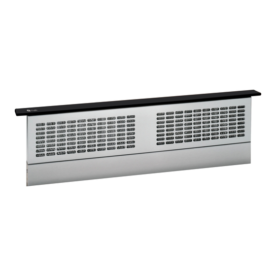
Installation Instructions 3 CONNECT POWER Plug power cord into properly grounded receptacle. 4 INSTALL FILTERS, CHECK OPERATION • Press the ON/OFF pad on the control to raise the vent. straight up and pull forward. Retainers Filter Tabs • Press the Fan Speed HIGHER pad to start the blower.
Need help?
Do you have a question about the PVB94 and is the answer not in the manual?
Questions and answers