Table of Contents
Advertisement
Quick Links
Advertisement
Chapters
Table of Contents

Related Manuals for GW Instek C-1200


Summary of Contents for GW Instek C-1200
- Page 1 LoRa Tester C-1200 USER MANUAL ISO-9001 CERTIFIED MANUFACTURER...
- Page 2 This manual contains proprietary information, which is protected by copyright. All rights are reserved. No part of this manual may be photocopied, reproduced or translated to another language without prior written consent of Good Will company. The information in this manual was correct at the time of printing. However, Good Will continues to improve products and reserves the rights to change specification, equipment, and maintenance procedures at any time without notice.
-
Page 3: Table Of Contents
Table of Contents SAFETY INSTRUCTIONS ..........5 Safety Symbols ............. 5 Safety Guidelines ..........6 GETTING STARTED ............9 C-1200 Introduction ..........10 Appearance ............12 First Use Instructions ........... 14 BASIC OPERATION ............26 Frequency Settings ..........27 Span Settings ............29 Amplitude Settings .......... - Page 4 C-1200 User Manual USING C-1200 PC SOFTWARE ........197 Transmitter (TX) Mode ......... 198 Receiver (RX) Mode ..........210 MP Test..............221 Specification Pretest Mode ........224 IO Extension ............232 APPENDIX ..............233 ASCII to Binary Coded Decimal Table ....233 C-1200 Specifications..........
-
Page 5: Safety Instructions
SAFETY INSTRUCTIONS AFETY INSTRUCTIONS This chapter contains important safety instructions that you must follow during operation and storage. Read the following before any operation to ensure your safety and to keep the instrument in the best possible condition. Safety Symbols These safety symbols may appear in this manual or on the instrument. -
Page 6: Safety Guidelines
C-1200 User Manual Safety Guidelines General Do not place any heavy object on the instrument. Guideline Avoid severe impact or rough handling that leads to damaging the instrument. CAUTION Do not discharge static electricity to the instrument. - Page 7 SAFETY INSTRUCTIONS Power Cord The connector that plugs into the socket outlet must Requirements be a grounding-type male plug designed for use in your region. It must have certification marks showing certification by an agency in your region. The connectors that plug into the Appliance Inlets (AC receptacle) must be an IEC 60320, sheet C13, female connector.
- Page 8 C-1200 User Manual Storage Location: Indoor environment Temperature: -20°C to 70°C Humidity: <90% (non condensing) Altitude:< 2,000 meters Do not dispose this instrument as unsorted municipal Disposal waste. Please use a separate collection facility or contact the supplier from which this instrument was purchased.
-
Page 9: Getting Started
This chapter provides a brief overview of the C- 1200, the package contents, instructions for first time use and an introduction to the front panel, rear panel. C-1200 Introduction ............ 10 Main Features ..................10 Accessories ..................11 Appearance ..............12 Front Panel .................. -
Page 10: C-1200 Introduction
C-1200 User Manual C-1200 Introduction C-1200, a LoRa tester with 4 channels TRx ports supporting both Sub-GHz and 2.4 GHz frequency band, is able to provide complete parameter setting of both LoRa and (G) FSK modulated signals. This document applies to device software version V3.03.180424_25. -
Page 11: Accessories
GETTING STARTED Diverse marker functions and features with Peak Table Four RF input/output channels 433.92M, 490M, 868M, 915M, 923M, 2400 MHz modulation output. The message content is editable. Two trigger outputs and one external trigger input. ... -
Page 12: Appearance
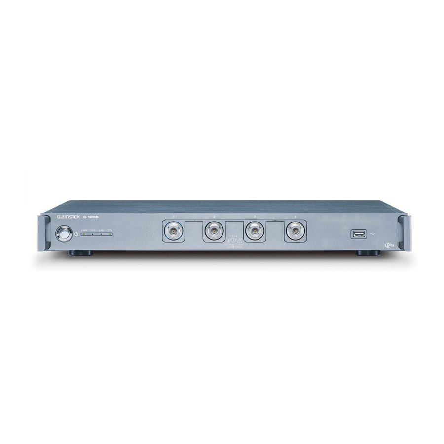
C-1200 User Manual Appearance Front Panel Turns the instrument on/off. 1. Power key It indicates system state. 2. LED RF input port. Accepts RF inputs. 3. RF input terminal Maximum input: +30dBm Input impedance: 50Ω RF INPUT 50W DC ±50V... -
Page 13: Rear Panel
GETTING STARTED Rear Panel BNC female 2.5V & 3.3V CMOS 1. TRIG OUT trigger output. OUT 1 OUT 1 OUT 2 TRIGGER BNC female 3.3V CMOS trigger 2. TRIG IN input/gated sweep input. OUT 2 BNC female reference output: 3. REF OUT 10MHz, 50Ω... -
Page 14: First Use Instructions
C-1200 User Manual First Use Instructions Use the procedures below when first using the C-1200 to tilt the stand, power up the instrument, update the firmware and to restore the default settings. Lastly, the Conventions sections will introduce you to the basic operating conventions used throughout the user manual. -
Page 15: Power Down
GETTING STARTED Power Down The C-1200 has two methods to power down: Description Normal and Forced Power Down. The normal power down method will save the system state and end any running processes. The state is saved for the next time the instrument is turned back on. -
Page 16: System Status
C-1200 User Manual System status The C-1200 has four status indicators. Each represents a different state. Power indictor. PWR LED This indicator lights in orange when the AC power cord is inserted to the power socket of the C-1200. This indicator lights in green when the power switch is turned on. - Page 17 GETTING STARTED updated. The C-1200 has four RF inputs. The RF input LED exterior of selected RF input port will light in blue. The C-1200 has four RF ouputs. The RF output exterior of selected RF ouput port will light...
- Page 18 “KL730819” of the 3rd segment applies to the “XXX” of http://gsp9300-XXX.local. For instance, http://gsp9300- 819.local. And here comes the other example for reference: GWINSTEK,C-1200,Sample003,V4.1.0.6, of which the “003” from “Sample003” of the 3rd segment applies to the “XXX” of http://C-1200-XXX.local. For instance, http://C-1200-003.local, which user can copy to browser and obtain the IP address as the red indicator below.
-
Page 19: Firmware Update
IP Address 192.168.1.100 Subnet Mask 255.255.255.0 Default Gateway 192.168.1.1 Firmware Update The C-1200 allows the firmware to be updated by Description end-users. Before using the C-1200, please ask your local distributor for the latest firmware. Before updating the firmware, please check the System version firmware version. -
Page 20: Method 1: Via Usb Flash Drive
The firmware version should be V3.0 above. 2. Insert the USB flash drive with updated file in the folder gsp3310 of root directory to the USB port on the C-1200 front panel. And then use the following command to updated the system. :SYSTem:UPDate 3. -
Page 21: Method 2: Through Tftp
GETTING STARTED Method 2: Through TFTP The C-1200 supports link between TFTP client and server. The firmware of C-1200 can be updated to the latest version through the remote control. 1. Use the RJ45 port and connect the TFTP server Steps to update the software via remote control. - Page 22 C-1200 User Manual TFTP default directory TFTP server IP 4. Copy the latest software to Current Directory. The latest software should contain four or more files, including arm_loopgpp_new, arm_loopgpp_new.md5, dsp_loop_new and dsp_loop_new.md5 (LoRa_MCU1, LoRa_MCU2)
- Page 23 Please check if the RJ45 connector is connected. Next, you need to use the following command to configure the IP address of the TFTP server in C-1200 through LAN. :SYSTem:COMMunicate:TFTP:ADDRess "172.16.22.99" You can also use the following command to query IP address of setting current TFTP server.
- Page 24 : SYSTem:UPDate TFTP server displays the data transfer status during the update process. The STA LED on the C-1200 front panel flashes quickly. C-1200 will reboot automatically after all updating process is complete. 7. After update is complete, you can use the following command to query the status of the last update process.
- Page 25 GETTING STARTED...
- Page 26 C-1200 User Manual ASIC OPERATION Frequency Settings ............27 Center Frequency................27 Start and Stop Frequency ..............27 Span Settings ...............29 Span ....................29 Full Span .................... 29 Amplitude Settings ............30 Reference Level .................. 30 Bandwidth Settings ............31 Resolution Bandwidth Setting (RBW) ..........31 Video Bandwidth Settings (VBW) .............
-
Page 27: Basic Operation
BASIC OPERATION Frequency Settings Center Frequency The center frequency function sets the center Description frequency and centers the display to the center frequency. SCPI command: Operation [:SENSe]:FREQuency:CENTer Range: 0kHz~3.25GHz Resolution: Default 1.625GHz Start and Stop Frequency The start/stop frequency function will set the start Description and stop frequency of the span. - Page 28 C-1200 User Manual The start and stop frequency can change when the Note span settings are used. The stop frequency must be set higher than the start frequency (for spans 0), otherwise the span will be automatically set to 100Hz.
-
Page 29: Span Settings
BASIC OPERATION Span Settings Span The Span function will set the frequency range of Description the sweep. The sweep will be centered on the center frequency. Setting the span will alter the start and stop frequencies. SCPI command: Operation [:SENSe]:FREQuency:SPAN Range: 0kHz~3.25GHz Resolution:... -
Page 30: Amplitude Settings
C-1200 User Manual Amplitude Settings The vertical display scale is defined by the reference level amplitude, attenuation, scale and external gain/loss. Reference Level The reference level defines the absolute level of the Description amplitude on the top graticule in voltage or power. -
Page 31: Bandwidth Settings
BASIC OPERATION Bandwidth Settings BW/AVG key sets the resolution bandwidth (RBW), video bandwidth (VBW) and averaging functions. The resolution, sweep time, and averaging are in a trade-off relationship, so configuration should be done with care. Resolution Bandwidth Setting (RBW) RBW (Resolution Bandwidth) defines the width of Description the IF (intermediate frequency) filter that is used to separate signal peaks from one another. -
Page 32: Video Bandwidth Settings (Vbw)
C-1200 User Manual Set the resolution bandwidth and unit for Man Operation mode. SCPI command: [:SENSe]:BANDwidth[:RESolution] Mode: Auto, Man Frequency Range(3dB): 1Hz~1MHz (1-3-10 step) Frequency Range(6dB): 200Hz, 9kHz, 120kHz, 1MHz Video Bandwidth Settings (VBW) VBW (Video Bandwidth) defines the smoothness Description of the trace on the display. -
Page 33: Sweep
BASIC OPERATION Sweep The C-1200 has a number of sweep options including setting the sweep time, the sweep run mode (continuous, single) and sweep mode (fast, slow). The C-1200 also has gated sweep modes. Sweep Time Sweep time defines the length of time the system Description takes to "sweep”... -
Page 34: Continuous Sweep
When a single sweep has been performed, you can still perform frequency, span, amplitude and other functions on the “frozen” trace. Continuous Sweep The C-1200 has two main sweeping run modes: Description single and continuous. Use the continuous mode to have the sweep constantly updated. -
Page 35: Trigger
Please refer to section “LoRa/ FSK Measurement” through page 38 to 49 for the further application. Trigger output: C-1200 provides two set of trigger output. Trigger output The trigger signal can be output via command as Description shown in the diagram below. -
Page 36: Rx Scan Mode
Both trigger output terminal can be used at to output at the same time. SCPI command: :OUTPut:TRIGger:IMMediate:AON RX scan mode The C-1200 has four RF input channels. The Description channels are switchable for receiving different signals Use the command to switch the input port. -
Page 37: Advanced Operation
ADVANCED OPERATION DVANCED OPERATION Measurement .............. 38 LoRa Measurement ................38 FSK Measurement ................44 2FSK Measurement ................49 2FSK Pass Fail Testing ..............53 RF generator ..................54 Manual Calibration ............59... -
Page 38: Measurement
C-1200 User Manual Measurement This section describes how to use the automatic measurement modes. The C-1200 includes the following measurements: LoRa Measurement → from page 38 FSK Measurement → from page 44 2FSK Measurement → from page 49 ... - Page 39 ADVANCED OPERATION [:SENSe]:LORA:RF:FREQuency It requires some additional delay time before and after the above command is executed. Note 100ms for delay time is highly recommended. 3. Turn on the LoRa mode and the decoder IC enters the standby mode simulataneously. SCPI command: :CALCulate:DEMod:LORA:STATe ON Confirm if it enters the LoRa mode.
- Page 40 C-1200 User Manual 5. Set the Spreading Factor, Coding rate, Bandwidth and IF Bandwidth of the LoRa signal. SCPI command: [:SENSe]:LORA:SF SCPI command: [:SENSe]:LORA:CRATe SCPI command: [:SENSe]:LORA:BWID|BAND SCPI command: [:SENSe]:DEMod:IFBW 6. Sets length of preamble, Low datarate optimize, Display View header type, AGC auto, LNA boost, Payload CRC.
- Page 41 ADVANCED OPERATION SCPI command: [:SENSe]:LORA:LDRO:STAte SCPI command: [:SENSe]:LORA:IMPLicit:HEADer:STAte SCPI command: [:SENSe]:LORA:RX:AGC:STAte SCPI command: [:SENSe]:LORA:LNABoost:STATe SCPI command: [:SENSe]:LORA:PayLoadCRCErrorState 7. Sets X axis to observe length of signal. Ref. Value Sets the starting time on the time axis. SCPI command: :DISPlay:DEMod[:WINDow]:TRA :X[:SCALe]:RVALue Ref.
- Page 42 C-1200 User Manual Scale/Div Sets the grid division scale. SCPI command: :DISPlay:DEMod[:WINDow]:TRA :X[:SCALe]:PDIVision 8. Sets Y axis to change scale of signal. Ref.Value Offsets the reference position as a percentage of the vertical scale/div. SCPI command: :DISPlay:DEMod[:WINDow]:TRA :Y[:SCALe]:RVALue Ref.Pos Sets the reference position of the waveform on a vertical grid subdivision (1:10).
- Page 43 ADVANCED OPERATION Auto Scale Toggles auto-scaling execution. SCPI command: :DISPlay:DEMod[:WINDow]:TRA :Y[:SCALe]:AUTO 9. Setting conditions for trigger mode (triggering Operation: conditions): AF trigger configuration Free Run Disables the trigger, this is the default setting. SCPI command: :TRIGger[:SEQuence]:DEMod :SOURce IMMediate RF Trigger Sets the RF trigger level: -80 to +16dBm SCPI command:...
-
Page 44: Fsk Measurement
C-1200 User Manual Mode Norm.: Normal trigger Sgl.: Single trigger Cont.: Continuously trigger SCPI command: :TRIGger[:SEQuence]:DEMod:MO Trigger Sets the trigger delay time: Delay 0 to 1ks SCPI command: :TRIGger[:SEQuence]:DEMod:DEL Action Now Turns Free Run mode off and uses the user-defined AF Trigger settings. - Page 45 ADVANCED OPERATION 1. Set the carrier frequency as center frequency. Operation: configuration SCPI command: [:SENSe]:FREQuency:CENTer 2. Turn on the FSK mode and the decoder IC enters the standby mode simultaneously. Any other measurement mode will automatically be disabled. SCPI command: :CALCulate:DEMod:FSK:STATe ON Confirm if it enters the FSK mode.
- Page 46 C-1200 User Manual Waveform view FSK measurements Spectrum view Symbol view 4. Set the Bit Rate and IF Bandwidth of the FSK signal. SCPI command: [:SENSe]:DEMod:BRATe 5. You can set the parameters for the vertical axis. Ref. Value Sets the starting time on the time axis.
- Page 47 ADVANCED OPERATION Scale/Div Sets the grid division scale when Auto Scale is Off. SCPI command: :DISPlay:DEMod[:WINDow]:TRA Ce:X[:SCALe]:PDIVision 6. You can set the parameters for the vertical axis. Ref.Value Offsets the reference position (in frequency). SCPI command: :DISPlay:DEMod[:WINDow]:TRA Ce:Y[:SCALe]:RVALue Ref.Pos Sets the reference position of the waveform on a vertical grid subdivision (1:10).
- Page 48 C-1200 User Manual configuration Free Run Disables the trigger, this is the default setting. SCPI command: :TRIGger[:SEQuence]:DEMod :SOURce IMMediate RF Trigger Sets the RF trigger level: -80 to +16dBm SCPI command: :TRIGger[:SEQuence]:DEMod :INTernal:LEVel Ext.Edge Sets the external trigger slope: Pos, Neg.
-
Page 49: 2Fsk Measurement
ADVANCED OPERATION Trigger Delay Sets the trigger delay time: 0 to 1ks SCPI command: :TRIGger[:SEQuence]:DEMod:DE Action Now Turns FreeRun mode off and uses the user-defined AF trigger settings. SCPI command: :TRIGger[:SEQuence]:DEMod :SOURce SCPI command: [:SENSe]:DEMod:DECode 2FSK Measurement 2FSK is a binary FSK (frequency shift keying) form Description of modulation. - Page 50 C-1200 User Manual Example Peak threshold limit Max Hold limit Max Hold trace 2FSK trace Freq. 2 Freq. 1 1. Set the frequency span to cover the 2FSK carrier Operation and hop frequency. 2. Turn on the 2FSK function. Any other...
- Page 51 ADVANCED OPERATION Threshold range: -120dBm ~ 30.0 dBm SCPI command: :CALCulate:MARKer:PEAK:THReshold :CALCulate:MARKer:PEAK:THReshold:STATe...
- Page 52 C-1200 User Manual 4. Set the max hold limit. Max Hold range: -130dBm ~ 30.0 dBm SCPI command: :DISPlay[:WINDow]:TRACe2:MODE:MAXHol 5. Recall the measurement value of peak1, peak2 and 2FSK by command. SCPI command: :CALCulate:BFSK:RESult? 6. The setting conditions of trigger mode...
-
Page 53: 2Fsk Pass Fail Testing
ADVANCED OPERATION 2FSK Pass Fail Testing The Limit Edit function puts a pass limit on the Description frequency deviation and carrier power and a high/low limit on the amplitude of each peak. Freq. Deviation: 1Hz ~ 400kHz Measurement Carr. Offset: 1Hz ~ 400kHz Range High Limit:... -
Page 54: Rf Generator
C-1200 User Manual Low Limit If the amplitude for one of the peaks is below the low limit, it will be judged as Fail. SCPI command: :CALCulate:BFSK:LIMit:LOW 2. Turn on Pass/Fail Test. 3. Recall the status of Pass/ Fail through commands. - Page 55 ADVANCED OPERATION LoRa mode: Operation: configuration 1. Set the output modulation mode. SCPI command: :CALCulate:DEMod:LORA:STATe ON Confirm if it enters the LoRa mode. SCPI command: *opc? 2. Set the output frequency: 433.92MHz Range: 433MHz to 435MHz 490MHz Range: 470MHz to 510MHz 868MHz Range: 862MHz to 875MHz 915MHz...
- Page 56 C-1200 User Manual 3. Set Spreading Factor, Coding rate, Bandwidth(Only available in LoRa mode) for LoRa. SCPI command: [:SENSe]:LORA:SF SCPI command: [:SENSe]:LORA:CRATe SCPI command: [:SENSe]:LORA:BWID|BAND 4. Set the Preamble length: 4 to 400 symbols SCPI command: [:SENSe]:LORA:PRELength 5. Set the output data in hexadecimal format.
- Page 57 ADVANCED OPERATION FSK mode: Set as FSK mode. SCPI command: :CALCulate:DEMod:FSK:STATe ON Confirm if it enters the FSK mode. SCPI command: *opc? Set the output frequency: 433.92MHz Range: 433MHz to 435MHz 490MHz Range: 470MHz to 510MHz 868MHz Range: 862MHz to 875MHz 915MHz Range: 900MHz to 928MHz 923MHz...
- Page 58 C-1200 User Manual FSK: Set the bit rate:1200, 2400, 4800, 9600, 19200, 38400, 57600, 76800, 115200 bps(Only available in FSK mode). SCPI command: :SENSe:TXPower:DEViation Set the deviation: 1kHz to 100kHz(Only available in FSK mode) SCPI command: :SENSe:TXPower:DEViation Set the Preamble length: 10 to 400 bytes...
-
Page 59: Manual Calibration
ADVANCED OPERATION Manual Calibration It is available to calibrate output level via manual Description: calibration when operating temperature is either below 20°C or above 30°C. 1. Set the command. Operation: configuration :SYSTem:TEMperature:GET 2. Wait for 2 seconds before setting the next command. -
Page 60: Remote Control
C-1200 User Manual EMOTE CONTROL This chapter describes the basic configuration of IEEE488.2 based remote control. This chapter includes interface configuration, a remote control overview as well as the control syntax and commands. Interface Configuration ..........61 Configure the LAN Interface ............. 62 Command Syntax ............ -
Page 61: Interface Configuration
And here comes the other example for reference: GWINSTEK,C-1200,Sample003,V4.1.0.6, of which the “003” from “Sample003” of the 3rd segment applies to the “XXX” of http://C-1200-XXX.local. For instance, http://C- 1200-003.local, which user can copy to browser and obtain the IP address as the red indicator below. -
Page 62: Configure The Lan Interface
C-1200 User Manual Configure the LAN Interface The C-1200 supports HiSlip. HiSlip (High-Speed LAN Instrument Protocol) is an advanced LAN based standard for 488.2 communications. The LAN interface is used for remote control over Background a network. The C-1200 supports DHCP connections so the instrument can be automatically connected to an existing network. - Page 63 REMOTE CONTROL DNS Server 172.16.1.252, 172.16.1.248 DHCP on/off Manual Connect an Ethernet cable from the Connection network to the rear panel LAN port. Use the following command to set the IP address. User Settings :SYSTem:COMMunicate:LAN:ADDRess 1. Use the following command to set the subnet mask.
-
Page 64: Command Syntax
C-1200 User Manual Command Syntax Full compatibility IEEE488.2 Compatible Full compatibility Standard SCPI, 1999 SCPI (Standard Commands for Programmable Command Instruments) commands follow a tree-like structure, Structure organized into nodes. Each level of the command tree is a node. Each keyword in a SCPI command represents each node in the command tree. - Page 65 REMOTE CONTROL Query A query is a simple or compound command followed by a question mark (?). A parameter (data) is returned. Example :CALCulate:BFSK:STATe? Compound Two or more commands on the same command line. Compound commands are separated with either a semi- colon (;) or a semi-colon and a colon (;:).
- Page 66 C-1200 User Manual Commands and queries have two different Command Forms forms, long and short. The command syntax is written with the short form of the command in capitals and the remainder (long form) in lower case. The commands can be written in capitals or lower-case, just so long as the short or long forms are complete.
- Page 67 REMOTE CONTROL Type Description Example Common Input Parameters <Boolean> Boolean logic 0, 1 <Binary> Binary data #B0101010001 <Hexadecimal Hexadecimal #H2345ACDF > data <NR1> integers 0, 1, 2, 3 <NR2> decimal 0.1, 3.14, 8.5 numbers <NR3> floating point 4.5e-1, 8.25e+1 <NRf> any of NR1, 2, 3 1, 1.5, 4.5e-1 <freq>...
- Page 68 C-1200 User Manual Note: The unit can be omitted (unit defaults to dB). Return: <NR3> 2.0e+1 Note: Units = dB. <ampl> Input: 30 mv NR3 +unit type Note: The unit can be omitted. (Unit defaults to current y-axis unit). Return: <NR3>...
- Page 69 REMOTE CONTROL Note: <digits> represents the data block length descriptor. Expressed as an integer number equal to the total number of <8 bit data bytes> that follows. <nonzero digit> represents the number of digits that are part of the data block length descriptor. Example: #41202<8 bit data bytes>...
-
Page 70: Status Registers
Status Registers Overview The status registers are used to determine the Description status of the C-1200. The status registers maintain the status of the pass/fail limits, trigger status and other operation statuses. The status registers are arranged in a number of groups: ... - Page 71 REMOTE CONTROL...
- Page 72 Event Enable Register The condition registers report the state of the Condition Registers C-1200. Condition registers can only be read. The positive transistion registers are used to PTR Registers filter for events that occur from a negative to a positive transition.
-
Page 73: Status Byte Register (Stb)
REMOTE CONTROL To higher order register Condition PTR / Event Enable Register Register Register & & & & & & & & & & Status Byte Register (STB) The Status Byte register consolidates the status Overview events of all the status registers. The Status Byte register can be cleared with the *CLS command. -
Page 74: Standard Event Status Register (Esr)
C-1200 User Manual ESB: This is the summary bit for the Standard Event Register. MSS/RQS: The MSS bit is the summary bit for the Service Request Enable Register. The RQS bit is set to 1 when the MSS bit is set to 1. -
Page 75: Operation Status Register
REMOTE CONTROL Operation Status Register The Operation Status Register Group indicates the Overview operating status of the C-1200. Weight Description Bit Summary Sweeping: Indicates that a sweep is in progress. Measuring: The instrument is currently performing a measurement. Waiting for Trigger: The instrument is in a “wait for trigger”... -
Page 76: Questionable Status Frequency Register
C-1200 User Manual Questionable Status Frequency Register The Questionable Status Frequency Register Overview indicates if the span or BW settings are invalid. Weight Description Bit Summary Invalid Span or BW: This bit is set to 1 when there is an invalid span or bandwidth (setting) during the frequency count. -
Page 77: Command List
REMOTE CONTROL Command List *CLS ................ 84 SCPI Commands *IDN? ..............84 *ESE ................ 85 *ESR? ..............85 *OPC ............... 85 *RST ................ 86 *SRE ................ 86 *STB? ..............86 *TST?............... 86 *WAI ................ 87 :CALCulate:BFSK:LIMit:STATe ....... 89 CALCulate :CALCulate:BFSK:LIMit:FAIL? ........ 89 Commands :CALCulate:BFSK:LIMit:FDEViation ....... - Page 78 C-1200 User Manual :CALCulate:MARKer<n>:NOISe:Y? ......99 :CALCulate:MARKer<n>:VSWR:STATe ....100 :CALCulate:MARKer<n>:VSWR:Y? ......100 :CALCulate:MARKer<n>:PEAK ....... 101 :CALCulate:MARKer:PEAK:CTRack:STATe ..... 101 :CALCulate:MARKer:PEAK:DATA? ......102 :CALCulate:MARKer:PEAK:EXCursion ....102 :CALCulate:MARKer:PEAK:SORT:TYPE ....102 :CALCulate:MARKer:PEAK:TABLe:STATe ....103 :CALCulate:MARKer:PEAK:THReshold ....103 :CALCulate:MARKer:PEAK:THReshold:STATe ..104 :CALCulate:MARKer<n>:SET ........104 :CALCulate:MARKer<n>:STATe......105 :CALCulate:MARKer:TABLe:STATe ......
- Page 79 REMOTE CONTROL :DISPlay[:WINDow]:TRACe:Y[:SCALe]:RLEVel:OFFSet ................. 115 :DISPlay[:WINDow]:TRACe:Y[:SCALe]:SPACing ..116 :INITiate:CONTinuous ........... 117 INITiate :INITiate[:IMMediate] ..........117 Commands :INPut:ATTenuation ..........118 INPut :INPut:ATTenuation:AUTO ........118 Commands :INPut:IMPedance ..........119 :INPut:OFFSet ............119 :OUTPut:TRIGger<n>:LEVel ........120 OUTPut :OUTPut:TRIGger<n>:IMMediate ......121 commands :OUTPut:TRIGger:IMMediate:AON ....... 121 :OUTPut:USBCable:FORmate ........
- Page 80 C-1200 User Manual [:SENSe]:BANDwidth|BWIDth[:RESolution] ..130 [:SENSe]:BANDwidth|BWIDth[:RESolution]:AUTO 131 [:SENSe]:BANDwidth|BWIDth:VIDeo ....131 [:SENSe]:BANDwidth|BWIDth:VIDeo:AUTO ..131 [:SENSe]:DEMod:BWIDth ........132 [:SENSe]:TXPower:DCFree ........132 [:SENSe]:DEMod:FDEViation ......... 133 [:SENSe]:DEMod:IFBW........... 133 [:SENSe]:DEMod:MEAS:WAVeform:LENGth ..133 [:SENSe]:LORA:PRELength ........134 [:SENSe]:TXPower:PREamble:SIZE ......134 [:SENSe]:TXPower:SYNChronous1:SIZe ....134 [:SENSe]:TXPower:SYNChronous:CONBination ... 135 [:SENSe]:TXPower:SYNChronous1:DATA [:SENSe]:DETector[:FUNCtion] ......
- Page 81 REMOTE CONTROL [:SENSe]:TXPower:STATe ........146 [:SENSe]:LORA:CRATe ..........146 [:SENSe]:LORA:IMPLicit:HEADer:STAte ....146 [:SENSe]:LORA:PAYLoad:CRC:STATe ....147 [:SENSe]:LORA:SF ..........147 [:SENSe]:LORA:BWIDth | BANDwidth ....148 [:SENSe]:LORA:TXOutputLevel ......148 [:SENSe]:LORA:LongRange:Mode ......149 [:SENSe]:LORA:STATe ..........149 [:SENSe]:LORA:IQ:INVert:STATe ......149 [:SENSe]:LORA:FREQuency:HOPPing:STATe ..150 [:SENSe]:LORA:FREQuency:HOPPing:PERiod ..150 [:SENSe]:LORA: SYNChronous:DATA ....
- Page 82 C-1200 User Manual :SYSTem:DATE ............162 :SYSTem:ERRor:CLEar ..........163 :SYSTem:ERRor[:NEXT]? ........163 :SYSTem:PRESet ............. 164 :SYSTem:REBoot ............ 164 :SYSTem:SHUTdown..........164 :SYSTem:TIME ............164 :SYSTem:UPDate ............ 164 :SYSTem:UPDate:FILEsystem ........ 165 :SYSTem:UPDate:METHod ........165 :SYSTem:UPDate:STATus? ........165 :SYSTem:VERSion:HARDware? ......165 :SYSTem:VERSion:SOFTware? ....... 166 :SYSTem:MCU:VERSion:SOFTware? .....
- Page 83 REMOTE CONTROL :TRIGger[:SEQuence]:DEMod:VIDeo:LEVel ... 181 :TRIGger[:SEQuence]:DEMod:MODE ....182 :TRIGger[:SEQuence]:DEMod:VIDeo:SLOPe ..182 :TRIGger[:SEQuence]:DEMod:SOURce ....182 :TRIGger[:SEQuence]:DEMod:SUBSequent ..183 :TRIGger[:SEQuence]:EXTernal:SLOPe ....183 :TRIGger[:SEQuence]:INTernal:LEVel ....185 :TRIGger[:SEQuence]:MODE ......... 185 :TRIGger[:SEQuence]:SOURce ....... 185 :TRIGger[:SEQuence]:VIDeo:FREQuency ....186 :TRIGger[:SEQuence]:VIDeo:LEVel ......186 :TRIGger[:SEQuence]:VIDeo:SLOPe ...... 186 :UNIT:PMETer:POWer ........... 188 UNIT commands :UNIT:POWer ............
-
Page 84: Cls
C-1200 User Manual SCPI Commands *CLS ................ 84 *IDN? ..............84 *ESE ................ 85 *ESR? ..............85 *OPC ............... 85 *RST ................ 86 *SRE ................ 86 *STB? ..............86 *TST? ..............86 *WAI ............... 87 *CLS The *CLS command clears the Standard Event... -
Page 85: Ese
REMOTE CONTROL Manufacturer: GWINSTEK Model number : C-1200 Serial number : XXXXXXXX Firmware version : V3.X.X.X *ESE Query Sets or queries the Standard Event Status Enable Description register. *ESE <NR1> Syntax *ESE? Query Syntax <NR1> 0~255 Parameter Return parameter <NR1> Returns the bit sum of the Standard Event Status Enable register. -
Page 86: Rst
Return parameter <NR1> Returns the bit sum of the Status Byte register with the MSS bit (bit 6). *TST? Query Returns the result of a self-test. The C-1200 does Description not support performing a selftest and thus will always return “0” for this query. -
Page 87: Wai
REMOTE CONTROL *TST? Query Syntax Return parameter 0 Returns “0” *WAI Prevents any other commands or queries from Description being executed until all outstanding commands have completed. *WAI Syntax... - Page 88 C-1200 User Manual CALCulate Commands :CALCulate:BFSK:LIMit:STATe ....... 89 :CALCulate:BFSK:LIMit:FAIL? ........ 89 :CALCulate:BFSK:LIMit:FDEViation ....... 90 :CALCulate:BFSK:LIMit:CARRier:OFFSet ....90 :CALCulate:BFSK:LIMit:HIGH ....... 90 :CALCulate:BFSK:LIMit:LOW ......... 91 :CALCulate:BFSK:RESTart ........91 :CALCulate:BFSK:RESult? ........91 :CALCulate:BFSK:STATe ......... 92 :CALCulate:DELTamarker<n>:PAIR:SPAN .... 92 :CALCulate:DELTamarker<n>:PAIR:CENTer ..92 :CALCulate:DELTamarker<n>:X ......93 :CALCulate:DELTamarker<n>:Y? ......
-
Page 89: Calculate:bfsk:limit:state
REMOTE CONTROL :CALCulate:MARKer:PEAK:THReshold:STATe ..104 :CALCulate:MARKer<n>:SET ........104 :CALCulate:MARKer<n>:STATe ......105 :CALCulate:MARKer:TABLe:STATe ......105 :CALCulate:MARKer<n>:TRACe ......105 :CALCulate:MARKer<n>:TRACe:AUTO ....106 :CALCulate:MARKer<n>:TYPE ........ 107 :CALCulate:MARKer<n>:X ........107 :CALCulate:MARKer<n>:Y? ........107 :CALCulate:NDB:BANDwidth? ....... 108 :CALCulate:BFSK:LIMit:STATe Query Sets or queries the state of the 2FSK (BFSK) limit Description function. -
Page 90: Commands :Calculate:bfsk:limit:fdeviation
C-1200 User Manual :CALCulate:BFSK:LIMit:FDEViation Query Sets or queries the frequency deviation limit for Description 2FSK. The frequency limit indicates the maximum frequency deviation for a pass judgement. :CALCulate:BFSK:LIMit:FDEViation <freq> Syntax :CALCulate:BFSK:LIMit:FDEViation? Query Syntax <freq> <NR3> frequency in Hz. Parameter/ Return Parameter... -
Page 91: Calculate:bfsk:limit:low
REMOTE CONTROL :CALCulate:BFSK:LIMit:HIGH? Query Syntax <ampl> <NR3> amplitude in dBm. Parameter/ Return Parameter :CALC:BFSK:LIM:HIGH? Example >3.000e+01 :CALCulate:BFSK:LIMit:LOW Query Sets or queries the 2FSK low limit. If the amplitude Description of the trace is above the low limit, it will be judged as Fail. -
Page 92: Calculate:bfsk:state
C-1200 User Manual Return parameter <freq deviation>,<carrier offset> <freq Frequency deviation in NRf deviation> format <carrier offset> Carrier offset in NRf format :CALC:BFSK:RES? Query Example >4.416666667e+04,4.416666667e+04 :CALCulate:BFSK:STATe Query Sets or queries the state of the 2FSK measurement Description function. :CALCulate:BFSK:STATe {OFF|ON|0|1}... -
Page 93: Calculate:deltamarker
REMOTE CONTROL Takes the current span between the chosen Description markers and relocates that center frequency to the chosen center frequency. :CALCulate:DELTamarker<n>:PAIR:CENTer Syntax <freq> <n> Marker number. Parameter <freq> <NRf> center frequency. :CALC:DELT1:PAIR:CENT 1e+9 Example :CALCulate:DELTamarker<n>:X Query Sets or queries the selected delta marker position. Description :CALCulate:DELTamarker<n>:X <freq>...:X -
Page 94: Calculate:demod:fsk:state
C-1200 User Manual Sets or queries whether the LoRa function is on or Description off. :CALCulate:DEMod:LORA:STATe {ON|OFF|0|1} Syntax :CALCulate:DEMod:LORA:STATe? Query Syntax Return parameter ON | 1 <boolean>On OFF | 0 <boolean>Off Return parameter 1 <boolean>On <boolean>Off :CALC:DEM:LORA:STAT? Query Example >0... -
Page 95: Calculate:demod:fsk:result:current
REMOTE CONTROL Reutrn Parameter <RSSI>,<SNR>,<Symbol rate>,<FEI>,<Preamble FEI>,<Payload FEI>,<Preamble BW>,<Payload BW>,<TOA> < RSSI > RSSI Value < SNR > SNR Value < Symbol rate > Symbol rate < FEI > FEI(Frequency Error Indicator) <Preamble FEI> FEI on the entire section of preamble <Payload FEI>... -
Page 96: Calculate:demod:fsk:result:minimum
C-1200 User Manual :CALC:DEM:FSK:RES:CURR? Query Example >8.749949037e+09, -6.023e+01, -8.749322018e+09, 9601 :CALCulate:DEMod:FSK:RESult:MINimum? Query Returns the minimum FSK measurements. Description :CALCulate:DEMod:FSK:RESult:MINimum? Query Syntax Reutrn Parameter <Freq Deviation>,<Carrier Power>,<Carrier Frequency Offset> <Freq. Deviation> FM deviation <Carr. Power> Carrier power <Carr. Freq Carrier frequency offset Offset>... -
Page 97: Calculate:marker:aoff
REMOTE CONTROL This command will reset the max and min records Description for the current demodulation analysis. :CALCulate:DEMod:RESet Syntax :CALCulate:MARKer:AOFF Turns all the markers off. Description :CALCulate:MARKer:AOFF Syntax :CALC:MARK:AOFF Example :CALCulate:MARKer<n>:FCOunt: RESolution Query Sets or queries the frequency counter resolution in Description Hz for the selected marker. -
Page 98: Calculate:marker
C-1200 User Manual :CALCulate:MARKer<n>:FCOunt: RESolution:AUTO Query Sets the frequency counter resolution Auto setting Description on/off. :CALCulate:MARKer<n>:FCOunt:RESolution:AU Syntax TO {ON|OFF|1|0} :CALCulate:MARKer<n>:FCOunt:RESolution:AU Query Syntax <n> <NR1>Marker number 1~6 Parameter Auto is off. Auto is on. Auto is off. Auto is on. Return parameter 0 Auto is off.:Fcount:resolution:auto -
Page 99: Calculate:marker
REMOTE CONTROL :CALC:MARKer1:FCO:STAT 1 Example :CALCulate:MARKer<n>:FCOunt:X? Query Returns the counter frequency of the selected Description marker in Hz. :CALCulate:MARKer<n>:FCOunt:X? Query Syntax <n> <NR1> Marker number 1~6. Parameter Return parameter <freq> <NR3> Frequency in Hz. :CALC:MARK1:FCO:X? Example >2.0083e+8 :CALCulate:MARKer<n>:NOISe:STATe Query Sets or queries the state of the Marker Noise Description function.:Fcount:x -
Page 100: Calculate:marker
C-1200 User Manual Returns the normalized noise level over a BW of Description 1Hz from the marker position. :CALCulate:MARKer<n>:NOISe:Y? Query Syntax <n> <NR1> Maker number 1~6. Parameter Normalized noise level in the Y-axis Return parameter <NR3> unit. :CALC:MARK1:NOIS:Y? Example >1.166e+2 :CALCulate:MARKer<n>:VSWR:STATe...:Vswr:state -
Page 101: Calculate:marker
REMOTE CONTROL <n> <NR1> Maker number 1~6. Parameter Return parameter <NR2> VSWR value. :CALC:MARK1:VSWR:Y? Example >1.35 :CALCulate:MARKer<n>:PEAK Sets the selected marker to the selected peak. Description :CALCulate:MARKer<n>:PEAK {MAXimum| Query Syntax MINimum|NEXT|RIGHt|LEFT} <n> <NR1> Marker number 1~6 Parameter MAXimum Highest peak value MIMimum Lowest peak value NEXT Next peak...:Peak -
Page 102: Calculate:marker:peak:data
C-1200 User Manual :CALCulate:MARKer:PEAK:DATA? Query Returns all the top 10 peak data values in CSV Description format (returns the contents of the peak table). The <csv data> data contains 10 pairs of data from the top 10 peaks. Each pair includes the peak frequency and the peak amplitude. -
Page 103: Calculate:marker:peak:table:state
REMOTE CONTROL :CALCulate:MARKer:PEAK:SORT:TYPE Syntax {FREQuency|AMPLitude} :CALCulate:MARKer:PEAK:SORT:TYPE? Query Syntax FREQuenc Sort by frequency. Parameter/ Return parameter AMPLitud Sort by amplitude. :CALC:MARK:PEAK:SORT:TYPE FREQ Example :CALCulate:MARKer:PEAK:TABLe:STATe Query Sets or queries the state of the Peak Table. Description :CALCulate:MARKer:PEAK:TABLe:STATe Syntax {ON|OFF|1|0} :CALCulate:MARKer:PEAK:TABLe:STATe? Query Syntax Turn peak table off. -
Page 104: Calculate:marker:peak:threshold:state
C-1200 User Manual Peak threshold. Note: the unit Return parameter <NR3> returned depends on the currently set vertical units. :CALC:MARK:PEAK:THR -3 dBm Example :CALCulate:MARKer:PEAK:THReshold: STATe Query Sets or queries the state of the Peak Threshold. Description :CALCulate:MARKer:PEAK:THReshold:STATe Syntax {ON|OFF|1|0} :CALCulate:MARKer:PEAK:THReshold:STATe? Query Syntax Turn peak threshold off. -
Page 105: Calculate:marker
REMOTE CONTROL :CALCulate:MARKer<n>:STATe Query Sets or queries the state of the selected marker. Description :CALCulate:MARKer<n>:STATe {ON|OFF|1|0} Syntax :CALCulate:MARKer<n>:STATe? Query Syntax <n> <NR1> Marker number 1~6 Parameter Turn the selected marker off. Turn the selected marker on. Turn the selected marker off. Turn the selected marker on.:State -
Page 106: Calculate:marker
C-1200 User Manual Assigns the selected marker to a trace. Queries Description which trace the selected marker is assigned to. :CALCulate:MARKer<n>:TRACe <trace name> Syntax :CALCulate:MARKer<n>:TRACe? Query Syntax <n> <NR1> Marker number 1~6 Parameter/ Return parameter <trace The name of the trace: (1, 2, 3, 4) name>...:Trace:auto -
Page 107: Calculate:marker
REMOTE CONTROL :CALCulate:MARKer<n>:TYPE Query Sets or queries the marker type. Description :CALCulate:MARKer<n>:TYPE Syntax {NORMal|DELTa} :CALCulate:MARKer<n>:TYPE? Query Syntax <n> <NR1> Marker number 1~6 Parameter/ Return parameter <NORMal Normal marker > <DELTa> Delta marker :CALC:MARK1:TYPE NORM Example :CALCulate:MARKer<n>:X Query Sets or returns the marker position in Hz. Description :CALCulate:MARKer<n>:X <freq>...:Type -
Page 108: Calculate:ndb:bandwidth
C-1200 User Manual <n> <NR1> Marker number 1~6 Parameter Return parameter <NR3> Power or voltage :CALC:MARK1:Y? Example >-5.43e+1 :CALCulate:NDB:BANDwidth? Query Returns the NdB bandwidth measurement. Description :CALCulate:NDB:BANDwidth? Query Syntax Return parameter <NR3> NdB bandwidth in Hz. :CALCulate:NDB:BANDwidth? Example >-5.43e+1... - Page 109 REMOTE CONTROL DISPlay Commands :DISPlay:DEMod[:WINDow]:FILTer:ALPHa ... 110 :DISPlay:DEMod[:WINDow]:FILTer:SYMBol ..110 :DISPlay:DEMod[:WINDow]:FILTer:MEASurement 110 :DISPlay:DEMod[:WINDow]:SYMBol:DATA? ..111 :DISPlay:DEMod[:WINDow]:SYMBol:SDATA? ..111 :DISPlay:DEMod[:WINDow]:TRACe:Y[:SCALe] :PDIVision ............... 111 :DISPlay:DEMod[:WINDow]:TRACe:Y[:SCALe] :RPOSition .............. 112 :DISPlay:DEMod[:WINDow]:TRACe:Y[:SCALe]:RVALue ................. 112 :DISPlay:DEMod[:WINDow]:SPECtrum ....112 :DISPlay[:WINDow]:NORMal ......... 113 :DISPlay[:WINDow]:TRACe<n>:MODE....113 :DISPlay[:WINDow]:TRACe<n>:MODE :MAXHold?113 :DISPlay[:WINDow]:TRACe:Y[:SCALe]:AUTO ..114 :DISPlay[:WINDow]:TRACe:Y[:SCALe] :PDIVision .
-
Page 110: Display:demod[:Window]:Filter:alpha
C-1200 User Manual :DISPlay:DEMod[:WINDow]:FILTer:ALPHa Query Sets alpha value of gaussian filter. Description :DISPlay:DEMod:FILTer:ALPHa <NR3> Syntax :DISPlay:DEMod:FILTer:ALPHa? Query Syntax <NR3> Range: 0.2 ~ 2 Parameter/ Return parameter :DISPlay:DEMod:FILTer:ALPHa 0.3 Example :DISPlay:DEMod[:WINDow]:FILTer:SYMBol Query Sets length of gaussian filter. Description :DISPlay:DEMod:FILTer: SYMBol Syntax... -
Page 111: Display:demod[:Window]:Symbol:data
REMOTE CONTROL :DISPlay:DEMod[:WINDow]:SYMBol:DATA? Query Returns all symbol data. Description :DISPlay:DEMod:WINDow:SYMBol:DATA? Query Syntax Return parameter <binary> or <4 bit data> … <hexadecimal > :DISP:DEM:SYMB:DATA? Example >#HEED2124...,HED2124...,..:DISPlay:DEMod[:WINDow]:SYMBol:SDAT Query Response to the latest symbol data after triggering. Description :DISPlay:DEMod:WINDow:SYMBol:SDATA? Query Syntax Return parameter <binary> or <4 bit data>... -
Page 112: Rposition
C-1200 User Manual :DISPlay:DEMod[:WINDow]:TRACe:Y [:SCALe]:RPOSition Query Sets or queries the Reference Position of the trace Description for AM/FM demodulation (y-axis grid division). :DISPlay:DEMod[:WINDow]:TRACe:Y[:SCALe]: Syntax RPOSition <integer> :DISPlay:DEMod[:WINDow]:TRACe:Y[:SCALe]: Query Syntax RPOSition? <integer> <NR1>1~10 Parameter/ Return parameter :DISP:DEM:TRAC:Y:RPOS 2 Example :DISPlay:DEMod[:WINDow]:TRACe:Y [:SCALe]:RVALue Query Sets or queries the Reference value. -
Page 113: Display[:Window]:Normal
REMOTE CONTROL 0 & OFF Disable the function of displaying the Parameter spectrum 1 & ON Enable the function of displaying the spectrum :DISP:DEM:SPEC ON Example :DISPlay[:WINDow]:NORMal Sets the display window to the normal trace mode. Description :DISPlay[:WINDow]:NORMal Syntax :DISP:NORM Example :DISPlay[:WINDow]:TRACe<n>:MODE Sets the operation mode of the selected trace. -
Page 114: Display[:Window]:Trace:y[:Scale]:Auto
C-1200 User Manual Return parameter <n> <NR1> Trace number. <NR3> :DISP:TRAC2:MODE:MAXH? Example >-2.000e+01 :DISPlay[:WINDow]:TRACe:Y[:SCALe]:AUTO Adjusts amplitude level to the most fitting Description position. :DISPlay[:WINDow]:TRACe:Y[:SCALe]:AUTO Syntax {ONCE} <ONCE> Compulsory parameter. Parameter :DISP:TRAC:Y:AUTO ONCE Example :DISPlay[:WINDow]:TRACe:Y[:SCALe] :PDIVision Query Sets or queries the Y-axis scale/div when the Description amplitude scale is logarithmic. -
Page 115: Display[:Window]:Trace:y[:Scale]:Rlevel
REMOTE CONTROL :DISPlay[:WINDow]:TRACe:Y[:SCALe]:POSition Syntax {LEFT|CENTer|RIGHt} :DISPlay[:WINDow]:TRACe:Y[:SCALe]:POSition? Query Syntax LEFT Position the scale to left Parameter/ Return parameter CENTer Position the scale to the center RIGHt Position the scale to right :DISP:TRAC:Y:POS LEFT Example :DISPlay[:WINDow]:TRACe:Y[:SCALe]: RLEVel Query Sets or queries the Y-axis reference level. The units Description depend on the scale type (logarithmic/linear). -
Page 116: Display[:Window]:Trace:y[:Scale]:Spacing
C-1200 User Manual :DISPlay[:WINDow]:TRACe:Y[:SCALe]: SPACing Query Sets or queries the type of scale: logarithmic or Description linear. :DISPlay[:WINDow]:TRACe:Y[:SCALe]:SPACing Syntax {LINear|LOGarithmic} :DISPlay[:WINDow]:TRACe:Y[:SCALe]:SPACing? Query Syntax LINear Linear scale Parameter/ Return parameter LOGarithmic Logarithmic scale :DISP:TRAC:Y:SPAC LOG Example... -
Page 117: Initiate:continuous
REMOTE CONTROL INITiate Commands :INITiate:CONTinuous ........... 117 :INITiate[:IMMediate] ..........117 :INITiate:CONTinuous Query Sets the sweep mode to continuous or single mode Description or queries its state. :INITiate:CONTinuous {OFF|ON|0|1} Syntax :INITiate:CONTinuous? Query Syntax single Parameter continuos single continuos Return parameter 0 single continuos :INIT:CONT ON... -
Page 118: Input:attenuation
C-1200 User Manual INPut Commands :INPut:ATTenuation ..........118 :INPut:ATTenuation:AUTO ........118 :INPut:IMPedance ..........119 :INPut:OFFSet ............119 :INPut:ATTenuation Query Sets or queries the input attenuation. Description :INPut:ATTenuation <integer> Syntax :INPut:ATTenuation? Query Syntax <integer> <NR1> 0 to 50 Parameter/ Return parameter... -
Page 119: Commands :Input:impedance
REMOTE CONTROL :INPut:IMPedance Query Sets or queries the input impedance in Ω. Description :INPut:IMPedance {50|75} Syntax :INPut:IMPedance? Query Syntax <NR1> Ω Parameter/ Return parameter <NR1> Ω :INP:IMP 75 Example :INPut:OFFSet Query Sets or queries the input offset (Input Z Description Calibration). -
Page 120: Output:trigger
C-1200 User Manual OUTPut Commands :OUTPut:TRIGger<n>:LEVel ........120 :OUTPut:TRIGger<n>:IMMediate ......121 :OUTPut:TRIGger:IMMediate:AON ....... 121 :OUTPut:USBCable:FORmate ........ 121 :OUTPut:USBCable:Reset ........121 :OUTPut:USBCable:SPI#:SETting ......121 :OUTPut:USBCable:SPI#:STRing:Write ....122 :OUTPut:USBCable:SPI#:STRing:Read ....122 :OUTPut:USBCable:SPI:REAd? ......122 :OUTPut:USBCable:UART#:STRing:Write ..... 122 :OUTPut:USBCable:UART#:STRing:Read? .... 123 :OUTPut:USBCable:I2C1:STRing:Write ....123 :OUTPut:USBCable:I2C1:STRing:REAd ....:Level -
Page 121: Output :Output:trigger
REMOTE CONTROL :OUTPut:TRIGger<n>:IMMediate Sets the selected trigger number to output. Description :OUTPut:TRIGger<n>:IMMediate Syntax <n> <NR1>trigger number 1~2 Parameter :OUTP:TRIG2:IMMediate Example :OUTPut:TRIGger:IMMediate:AON Sets two trigger to output. Description :OUTPut:TRIGger:IMMediate:AON Syntax :OUTP:TRIG:IMM:AON Example :OUTPut:USBCable:FORmate Sets output format as either HEX or String. Description HEXadecimal Sets output format as Hexadecimal.:Immediate -
Page 122: Output:usbcable:spi#:String:write
C-1200 User Manual :OUTPut:USBCable:SPI#:STRing:Write Sets SPI String write setting. Description SPI Channel 1, 2, 3, 4 Parameter IO Extension The initial H is necessarily required. Position Numeric length is from 1 to 100, and each digit ranges from 0 to F. -
Page 123: Output:usbcable:uart#:String:read
REMOTE CONTROL :OUTPut:USBCable:UART#:STRing:Read? Query Reads the UART String setting from IO Extension. Description UART Channel 1, 2, 3, 4 Parameter :OUTPut:USBCable:UART1:STRing:Read? Example :OUTPut:USBCable:I2C1:STRing:Write Sets I2C String write setting. Description IO Extension The initial H is necessarily required. Parameter Position Numeric length is from 1 to 100, and each digit ranges from 0 to F. -
Page 124: Output:usbcable:interface
C-1200 User Manual :OUTPut:USBCable:INterface? Query Returns the currently applied interface. Description :OUTPut:USBCable:INterface? Example :OUTPut:USBCable:GPIO#:STATe Sets the state of GPIO Description HIGH, LOW, INPUT State Parameter 1, 2 GPIO Channel :OUTPut:USBCable:GPIO1:STATe HIGH Example :OUTPut:USBCable:GPIO#:STATe? Query Returns the current state of GPIO. - Page 125 REMOTE CONTROL SENSe Commands [:SENSe]:ASET:AMPLitude ........127 [:SENSe]:ASET:AMPLitude:AUTO ......127 [:SENSe]:ASET:RUN ..........127 [:SENSe]:ASET:SPAN ..........128 [:SENSe]:ASET:SPAN:AUTO ........129 [:SENSe]:AVERage:COUNt ........129 [:SENSe]:AVERage:STATe ........129 [:SENSe]:AVERage:TYPE ......... 130 [:SENSe]:BANDwidth|BWIDth[:RESolution] ..130 [:SENSe]:BANDwidth|BWIDth[:RESolution]:AUTO 131 [:SENSe]:BANDwidth|BWIDth:VIDeo ....131 [:SENSe]:BANDwidth|BWIDth:VIDeo:AUTO ..131 [:SENSe]:DEMod:BWIDth........132 [:SENSe]:TXPower:DCFree ........
- Page 126 C-1200 User Manual [:SENSe]:SWEep:TIME ..........141 [:SENSe]:SWEep:TIME:AUTO ........ 141 [:SENSe]:TXPower:ATTenuation ......142 [:SENSe]:TXPower:BAUD ........142 [:SENSe]:TXPower:CH<n>:MODE ......143 [:SENSe]:TXPower:DATA ........143 [:SENSe]:LORA:PLOADLength ....... 143 [:SENSe]:TXPower:FREQuency:DEViation ..... 144 [:SENSe]:LORA:RF:FREQuency ......144 [:SENSe]:TXPower:PREamble ......... 145 [:SENSe]:TXPower:PREamble:POLarity ....145 [:SENSe]:TXPower:STATe ........146 [:SENSe]:LORA:CRATe ........... 146 [:SENSe]:LORA:IMPLicit:HEADer:STAte ....
-
Page 127: [:Sense]:Aset:amplitude
REMOTE CONTROL [:SENSe]:TXPower:AFC:FILTer:BWIDth ....158 [:SENSe]:TXPower:BANDwidth ......158 [:SENSe]:TXPower:MODulation:INDex ....159 [:SENSe]:ASET:AMPLitude Query Sets or queries the autoset amplitude floor level. Description [:SENSe]:ASET:AMPLitude <ampl> Syntax [:SENSe]:ASET:AMPLitude? Query Syntax <ampl> <NRf> power or voltage Parameter Return parameter <NR3> :ASET:AMPL 8.0e+1 Example [:SENSe]:ASET:AMPLitude:AUTO Query Sets autoset amplitude floor level to auto or... -
Page 128: [:Sense]:Aset:span
C-1200 User Manual Activates the Autoset function. Description [:SENSe]:ASET:RUN Syntax :ASET:RUN Example [:SENSe]:ASET:SPAN Query Sets or queries the Autoset span. Description [:SENSe]:ASET:SPAN <freq> Syntax [:SENSe]:ASET:SPAN? Query Syntax <freq> <NRf> Parameter Return parameter <NR3> :ASET:SPAN 2.0e+6 Example... -
Page 129: [:Sense]:Aset:span:auto
REMOTE CONTROL [:SENSe]:ASET:SPAN:AUTO Query Turns the Autoset span to auto or manual or Description queries its state. [:SENSe]:ASET:SPAN:AUTO {OFF|ON|0|1} Syntax [:SENSe]:ASET:SPAN:AUTO? Query Syntax Turn Autoset span to manual (off). Parameter Turn Autoset span to automatic (on). Turn Autoset span to manual (off). Turn Autoset span to automatic (on). -
Page 130: [:Sense]:Average:type
C-1200 User Manual Turn the Average function off. Parameter Turn the Average function on. Turn the Average function off. Turn the Average function on. Return parameter 0 The Average function is off. The Average function is on. :AVER:STAT ON Example... -
Page 131: [:Sense]:Bandwidth|Bwidth[:Resolution]:Auto
REMOTE CONTROL [:SENSe]:BANDwidth|BWIDth [:RESolution]:AUTO Query Turns the RBW to auto (on) or manual (off) or Description queries its state. [:SENSe]: Syntax BANDwidth|BWIDth[:RESolution]:AUTO {OFF|ON|0|1} [:SENSe]: Query Syntax BANDwidth|BWIDth[:RESolution]:AUTO? Turn RBW to manual (off). Parameter Turn RBW to automatic (on). Turn RBW to manual (off). Turn RBW to automatic (on). -
Page 132: [:Sense]:Demod:bwidth
C-1200 User Manual [:SENSe]:BANDwidth|BWIDth:VIDeo:AUTO Syntax {OFF|ON|0|1} [:SENSe]:BANDwidth|BWIDth:VIDeo:AUTO? Query Syntax Turn VBW to manual (off). Parameter Turn VBW to automatic (on). Turn VBW to manual (off). Turn VBW to automatic (on). Return parameter 0 VBW is set to manual (off). VBW is set to automatic (on). -
Page 133: [:Sense]:Demod:fdeviation
REMOTE CONTROL [:SENSe]:DEMod:FDEViation Query Sets or queries the frequency deviation in Description demodulation mode. [:SENSe]:DEMod:FDEViation <freq> Syntax <freq> <NRf> Parameter :SENS:DEM:FDEV 10kHz Example [:SENSe]:DEMod:IFBW Query Sets or queries the IF bandwidth for the LoRa/FSK Description Analysis function. [:SENSe]:DEMod:IFBW <freq> Syntax [:SENSe]:DEMod:IFBW? Query Syntax <freq>... -
Page 134: [:Sense]:Lora:prelength
C-1200 User Manual <integer> <NR1>Length 10~255 Parameter/ Retrun parameter :DEMod:MEAS:WAVeform:LENG 255 Example [:SENSe]:LORA:PRELength Query Sets or queries the number of preamble for the Description LoRa Analysis function. [:SENSe]:LORA:PRELength <integer> Syntax [:SENSe]:LORA:PRELength? Query Syntax <integer> <NR1> 10~400 Parameter / Return parameter... -
Page 135: [:Sense]:Txpower:synchronous:conbination
REMOTE CONTROL Sets or queries the number of sync bits for the FSK Description Analysis function. [:SENSe]:TXPower:SYNChronous1:SIZe <integer> Syntax [:SENSe]:TXPower:SYNChronous1:SIZe? Query Syntax <integer> <NR1> Frequency 1G below, 0~8 Parameter / Return parameter Frequency 2.4G,0~5 :TXP:SYNC1: SIZ? Example >4 [:SENSe]:TXPower:SYNChronous:CONBinat Query Sets if synchronous word is enabled or disabled Description when FSK is in the frequency 2.4GHz. -
Page 136: [:Sense]:Detector[:Function]
C-1200 User Manual <hexadecimal 0000~FFFF Parameter / Return parameter > :TXP:SYNC1:DATA? Example >#H2E3B [:SENSe]:DETector[:FUNCtion] Query Sets or queries the trace detection mode when in Description manual mode. [:SENSe]:DETector[:FUNCtion] {AVERage | Syntax SAMPle | POSitive | NEGative | NORMal | RAVerage | EAVerage | QPEak}... -
Page 137: [:Sense]:Frequency:center
REMOTE CONTROL Turn the detection mode to manual Parameter (off). Turn the detection mode to auto (on). Turn the detection mode to manual (off). Turn the detection mode to auto (on). Return parameter 0 The detection mode is set to manual. The detection mode is set to automatic. -
Page 138: [:Sense]:Frequency:offset
C-1200 User Manual Turns the CF Step frequency setting to auto (on) or Description manual (off) or queries its state. [:SENSe]:FREQuency:CENTer:STEP:AUTO Syntax {OFF|ON|0|1} [:SENSe]:FREQuency:CENTer:STEP:AUTO? Query Syntax Turn CF Step to manual (off). Parameter Turn CF Step to auto (on). Turn CF Step to manual (off). -
Page 139: [:Sense]:Frequency:span:full
REMOTE CONTROL [:SENSe]:FREQuency:SPAN:FULL Set the span to Full Span. Description [:SENSe]:FREQuency:SPAN:FULL Syntax :FREQ:SPAN:FULL Example [:SENSe]:FREQuency:SPAN:PREVious Set the span to the previous span setting. Description [:SENSe]:FREQuency:SPAN:PREVious Syntax :FREQ:SPAN:PREV Example [:SENSe]:FREQuency:STARt Query Sets or queries the start frequency. Description [:SENSe]:FREQuency:STARt <freq> Syntax [:SENSe]:FREQuency:STARt? Query Syntax <freq>... -
Page 140: [:Sense]:Sweep:egate:delay
C-1200 User Manual [:SENSe]:SWEep:EGATe:DELay Query Sets or queries the gate delay time. Description [:SENSe]:SWEep:EGATe:DELay <time> Syntax [:SENSe]:SWEep:EGATe:DELay? Query Syntax <time> Gate delay time in seconds Parameter/ Return parameter :SWE:EGAT:DEL 10 ms Example [:SENSe]:SWEep:EGATe:LENGth Query Sets or queries the gate length time. -
Page 141: [:Sense]:Sweep:mode
REMOTE CONTROL :SWE:EGAT:STAT 1 Example [:SENSe]:SWEep:MODE Query Sets or queries the sweep mode. Description :SENSe:SWEep:MODE {FAST|NORMal} Syntax :SENSe:SWEep:MODE? Query Syntax FAST Sets to fast mode Parameter NORMAL Sets to normal mode Return parameter FAST Sets to fast mode NORMAL Sets to normal mode :SENS:SWE:MODE FAST Example [:SENSe]:SWEep:TIME... -
Page 142: [:Sense]:Txpower:attenuation
C-1200 User Manual Turn sweep time to auto (on). Return parameter 0 Sweep time is set to manual. Sweep time is set to automatic. :SWE:TIME 60 ms Example [:SENSe]:TXPower:ATTenuation Query Sets or queries the current attenuation of TX. Description [:SENSe]:TXPower: ATTenuation <ampl>... -
Page 143: [:Sense]:Txpower:ch
REMOTE CONTROL [:SENSe]:TXPower:CH<n>:MODE Query Sets or queries the chosen TX/RX port number is Description on/off. [:SENSe]:TXPower:CH<n>:MODE Syntax {OFF|ON|0|1} :TXPower:CH<n>:MODE? Query Syntax <n> <NR1> port number 1~4 Parameter Changes to input. Changes to output. Changes to input. Changes to output. Return parameter 0 Input mode Output mode :TXP:CH3:MODE ON...:Mode -
Page 144: [:Sense]:Txpower:frequency:deviation
C-1200 User Manual [:SENSe]:LORA:PLOADLength? Query Syntax <integer> <NR1>1~255. Parameter/ Return parameter : LoRa: PLOADL 10 Example [:SENSe]:TXPower:FREQuency:DEViation Query Sets or queries the TX deviation in FSK Description modulation. [:SENSe]:TXPower:FREQuency:DEViation <freq> Syntax Sets or queries the deviation of TX in FSK Query Syntax modulation. -
Page 145: [:Sense]:Txpower:preamble
REMOTE CONTROL <freq> <NR3>frequency in Hz. Parameter/ 166MHz~172MHz, Return parameter 430MHz~436MHz, 467MHz~473MHz, 487MHz~493MHz, 865MHz~871MHz, 912MHz~918MHz, 920MHz~926MHz, 2397MHz~2403MHz, :LORA:RF:FREQuency 433.92e6 Example [:SENSe]:TXPower:PREamble Query Sets or queries the number of preamble bytes of Description [:SENSe]:TXPower:PREamble <integer> Syntax [:SENSe]:TXPower:PREamble? Query Syntax <integer> <NR1>0~400. Parameter/ Return parameter :TXP:PRE 2... -
Page 146: [:Sense]:Txpower:state
C-1200 User Manual [:SENSe]:TXPower:STATe Sets the output data of TX in the FSK mode. Description [:SENSe]:TXPower:STATe {ON|OFF|1|0} Syntax [:SENSe]:TXPower:STATe? Query Syntax Sets FSK as output. Parameter Sets FSK as receive. Sets FSK as output. Sets FSK as receive. :TXP:STAT ON... -
Page 147: [:Sense]:Lora:payload:crc:state
REMOTE CONTROL Sets header mode under LoRa mode. Description [:SENSe]:LORA:IMPLicit:HEADer:STAte Syntax {OFF|ON|0|1} [:SENSe]:LORA:IMPLicit:HEADer:STAte? Query Syntax Sets header type as implicit. Parameter Sets header type as explicit. Sets header type as implicit. Sets header type as explicit. Return parameter 0 Header type is implicit. Header type is explicit. -
Page 148: [:Sense]:Lora:bwidth | Bandwidth
C-1200 User Manual Spreading factor is set 5, which is only Parameter available for 2400MHz. Return parameter SF6 Spreading factor is set 6. Spreading factor is set 7. Spreading factor is set 8. Spreading factor is set 9. SF10 Spreading factor is set 10. -
Page 149: [:Sense]:Lora:longrange:mode
REMOTE CONTROL :LORA:TXOutputLevel -10 Example [:SENSe]:LORA:LongRange:Mode Query Sets working LoRa or FSK mode. Description [:SENSe]:LORA:LongRange:Mode {FSK|LoRa} Syntax [:SENSe]:LORA:LongRange:Mode? Query Syntax LoRa LoRa mode Parameter FSK mode. Return parameter LoRa LoRa mode. FSK mode. :LORA:LongRange:Mode LoRa Example [:SENSe]:LORA:STATe Sets if LoRa is receive or send mode. Description [:SENSe]:LORA:STATe {OFF|ON|0|1} Syntax... -
Page 150: [:Sense]:Lora:frequency:hopping:state
C-1200 User Manual Enable IQ invert state. Disable IQ invert state. Enable IQ invert state. Return parameter 0 IQ invert state disabled IQ invert state enabled : LoRa:IQ:INVert:STATe 1 Example [:SENSe]:LORA:FREQuency:HOPPing:STAT Query Sets frequency hopping. Description [:SENSe]:LORA:FREQuency:HOPPing:STATe Syntax {OFF|ON|0|1} [:SENSe]:LORA:FREQuency:HOPPing:STATe? -
Page 151: [:Sense]:Lora: Synchronous:data
REMOTE CONTROL LoRa:FREQuency:HOPPing:PERiod 4 Example [:SENSe]:LORA: SYNChronous:DATA Query Sets Sync word. Description [:SENSe]:LORA: SYNChronous:DATA Syntax [:SENSe]:LORA: SYNChronous:DATA? Query Syntax <hexadeci 0x00~0xFF Parameter mal> Return parameter [:SENSe]:LORA:SYNChronous:DATA #H18 Example [:SENSe]:NDB:BANDwidth Query Measures NdB bandwidth under LoRa mode. Description [:SENSe]:NDB:BANDwidth <rel_amp> Syntax [:SENSe]:NDB:BANDwidth? Query Syntax <integer>... -
Page 152: [:Sense]:Txpower:address:base:filtering
C-1200 User Manual CONTinuou Continuous mode. Return parameter PACKet Packet mode. CONTinuou Continuous mode. [:SENSe]:TXPower:DATA:MODE PACKet Example [:SENSe]:TXPower:ADDRess:BASE:FILTerin Query Sets comparison method for address under FSK Description receive mode. [:SENSe]:TXPower:ADDRess:BASE:FILTering Syntax {OFF | NODE | BROAd } [:SENSe]:TXPower:ADDRess:BASE:FILTering? Query Syntax... -
Page 153: [:Sense]:Txpower:broadcast:address
REMOTE CONTROL [:SENSe]:TXPower:NODE:ADDRess #H24 Example [:SENSe]:TXPower:BROAdcast:ADDRess Query Broadcast address used in address filtering. Description [:SENSe]:TXPower:BROAdcast:ADDRess Syntax #H<hexadecimal> [:SENSe]:TXPower:BROAdcast:ADDRess? Query Syntax <hexadeci 0x00~0xFF Parameter mal> Return parameter [:SENSe]:TXPower:BROAdcast:ADDRess #H24 Example [:SENSe]:TXPower:DATA:LENGth Query Sets how many bytes to output for FSK payload. Description [:SENSe]:TXPower:DATA:LENGth <integer>... -
Page 154: [:Sense]:Txpower:crc:calculation:state
C-1200 User Manual CRC calculation utilizes IBM Parameter algorithm. Return parameter CCITT CRC calculation utilizes CCITT algorithm. :TXPower:CRC:POLYnom IBM Example [:SENSe]:TXPower:CRC:CALCulation:STATe Query Enables or disables crc. Description [:SENSe]:TXPower:CRC:CALCulation:STATe Syntax {0|1|2} [:SENSe]:TXPower:CRC:CALCulation:STATe? Query Syntax CRC off Parameter Return parameter 1 CRC on when frequency is below 1GHz. -
Page 155: [:Sense]:Txpower:agc:start:state
REMOTE CONTROL [:SENSe]:TXPower:AFC:AUTO:STATe? Query Syntax Parameter Return parameter 0 off. :TXPower:AFC:AUTO:STATe 1 Example [:SENSe]:TXPower:AGC:STARt:STATe Query Sets if AGC function is enabled. Description [:SENSe]:TXPower:AGC:STARt:STATe Syntax {OFF|ON|0|1} [:SENSe]:TXPower:AGC:STARt:STATe? Query Syntax Parameter Return parameter 0 off. :TXPower:AGC:STARt:STAT 1 Example [:SENSe]:TXPower:PREAmble:DECTection:S TATe Query Sets if preamble detector is enabled. Description [:SENSe]:TXPower:PREAmble:DECTection:STATe Syntax... -
Page 156: [:Sense]:Txpower:modulation:shape
C-1200 User Manual Return parameter 0 off. :TXPower:PREAmble:DECTection:STATe 1 Example [:SENSe]:TXPower:MODulation:SHAPe Query Data shaping is only available under FSK mode. Description [:SENSe]:TXPower:MODulation:SHAPe <0 | 1 | 2 Syntax | 3> [:SENSe]:TXPower:MODulation:SHAPe? Query Syntax no shaping Parameter Gaussian filter BT = 1.0 Return parameter Gaussian filter BT = 0.5... -
Page 157: [:Sense]:Txpower:plllock
REMOTE CONTROL [:SENSe]:TXPower:PLLLock Query Sets PLL setting under FSK mode. Description [:SENSe]:TXPower:PLLLock {ALLOFF | Syntax WITHPlllock | WITHoutplllock} [:SENSe]:TXPower:PLLLock? Query Syntax ALLOFF off. Parameter Return parameter WITHPlllock Waits for PLL relock. WITHoutpllloc No waits for PLL relock. :TXPower:PACket:FORMat VARiable Example [:SENSe]:TXPower:GFSK:STATe When FSK is in 2.4GHz frequency band and Description... -
Page 158: [:Sense]:Txpower:afc:filter:bwidth
C-1200 User Manual <freq> <NRf> Parameter 2.6k, 3.1k, 3.9k, 5.2k, 6.3k, 7.8k, 10.4k, 12.5k, 15.6k, 20.8k, 25k, 31.3k, 41.7k, 50k, 62.5k, 83.3k, 100k, 125k, 166.7k, 200k, 250kHz. Return parameter <NR3> :TXPower:CHANnel:FILTer:BWID 3.0e+5 Example [:SENSe]:TXPower:AFC:FILTer:BWIDth Query Sets bandwidth of AFC channel filter. -
Page 159: [:Sense]:Txpower:modulation:index
REMOTE CONTROL <integer> Bandwidth:2.4MHz, which can be set Parameter/ only for baud rate 2000e3, 1600e3 and Return parameter 1000e3 only. Bandwidth:1.2MHz, which can be set only for baud rate 1000e3, 800e3 and 400e3 only. Bandwidth:600kHz, which can be set only for baud rate 500e3, 400e3 and 250e3 only. -
Page 160: System:communicate:lanreset
C-1200 User Manual SYSTem Commands :SYSTem:COMMunicate:LANReset ....... 160 :SYSTem:COMMunicate:LAN:ADDRess ....160 :SYSTem:COMMunicate:LAN:CONFigure .... 161 :SYSTem:COMMunicate:LAN:DNS ....... 161 :SYSTem:COMMunicate:LAN:GATEway ....161 :SYSTem:COMMunicate:LAN:MASK ..... 162 :SYSTem:COMMunicate:TFTP:ADDRess ....162 :SYSTem:DATE ............162 :SYSTem:ERRor:CLEar ..........163 :SYSTem:ERRor[:NEXT]? ........163 :SYSTem:PRESet ............. 164 :SYSTem:REBoot ............ 164 :SYSTem:SHUTdown .......... -
Page 161: Commands :System:communicate:lan:configure
REMOTE CONTROL :SYSTem:COMMunicate:LAN:ADDRess <ip> Syntax :SYSTem:COMMunicate:LAN:ADDRess? Query Syntax <ip> “xxx.xxx.xxx.xxx” in ipv4. Parameter/ Return parameter :SYST:COMM:LAN:ADDR “172.16.22.72” Example :SYSTem:COMMunicate:LAN:CONFigure Query Set or query the IP configuration mode of the LAN Description :SYSTem:COMMunicate:LAN:CONFigure Syntax {DHCP|MANUAL} :SYSTem:COMMunicate:LAN:CONFigure? Query Syntax DHCP The network connection is set Parameter/ automatically Return parameter... -
Page 162: System:communicate:lan:mask
C-1200 User Manual :SYSTem:COMMunicate:LAN:GATEway <ip> Syntax :SYSTem:COMMunicate:LAN:GATEway? Query Syntax <ip> “xxx.xxx.xxx.xxx” in ipv4. Parameter/ Return parameter :SYST:COMM:LAN:GATE “172.16.1.254” Example :SYSTem:COMMunicate:LAN:MASK Query Set or query the IP address of subnet mask Description :SYSTem:COMMunicate:LAN:MASK <ip> Syntax :SYSTem:COMMunicate:LAN:MASK? Query Syntax <ip> “xxx.xxx.xxx.xxx” in ipv4. -
Page 163: System:error:clear
REMOTE CONTROL <year> <NR1> Parameter/ Return parameter <month> <NR1> <day> <NR1> :SYST:DATE 2011,03,27 Example :SYSTem:ERRor:CLEar Clears the error messages from the error queue. Description :SYSTem:ERRor:CLEar Syntax :SYSTem:ERRor[:NEXT]? Query Returns the next message from the error queue. Description Reading the error from the error queue will clear that error from the queue. -
Page 164: System:preset
C-1200 User Manual :SYSTem:PRESet Returns the C-1200 to preset settings. Description :SYST:PRES Syntax :SYSTem:REBoot Restart/Reboot the C-1200. Description :SYSTem:REBoot Syntax :SYSTem:SHUTdown Shut down the C-1200. Description :SYST:SHUT Syntax :SYSTem:TIME Query Sets the system time. Description :SYSTem:TIME <hour>,<minute>,<second> Syntax :SYSTem:TIME? Query Syntax <hour>... -
Page 165: System:update:filesystem
REMOTE CONTROL 1. Update method-USB:The firmware files must Warning be included in the directory named /gsp3310. 2. Update method-TFTP:The firmware files must be included in the root directory of TFTP server. :SYSTem:UPDate Syntax :SYST:UPD Example :SYSTem:UPDate:FILEsystem Updates the system with new filesystem. Description Update method-USB: The filesystem files must be Warning... -
Page 166: System:version:software
C-1200 User Manual Returns the system firmware version. Description :SYSTem:VERSion:HARDware? Query Syntax Return parameter <string> “V.X.X.X.X” :SYST:VERS:HARD? Example >”V.3.0.0.0” :SYSTem:VERSion:SOFTware? Query Returns the system software version. Description :SYSTem:VERSion:SOFTware? Query Syntax Return parameter <string> “V3.00” :SYST:VERS:SOFT? Example > “V3.00” :SYSTem:MCU:VERSion:SOFTware? Query Returns the MCU software version. -
Page 167: System:self:calibration:loop:state
REMOTE CONTROL :SYSTem:SELF:CALibration:LOOP:STATe Sets auto calibration hourly Description Syntax :SYSTem:SELF:CALibration:LOOP:STATe parameter Example :SYSTem:SELF:CALibration:LOOP:STATe 1 :SYSTem:TEMperature:GET Query Queries the internal temperature of unit Description :SYSTem:TEMperature:GET Query Syntax Return parameter <NR2> Temperature value Example :SYSTem:TEMperature:GET followed by :SYSTem:TEMperature:GET? > 26.1... -
Page 168: Status:operation:condition
C-1200 User Manual STATus Commands :STATus:OPERation:CONDition? ......168 :STATus:OPERation:ENABle ........169 :STATus:OPERation[:EVENt]? ........ 169 :STATus:OPERation:NTRansition ......169 :STATus:OPERation:PTRansition ......170 :STATus:QUEStionable:CONDition? ..... 170 :STATus:QUEStionable:ENABle ......171 :STATus:QUEStionable[:EVENt]? ......171 :STATus:QUEStionable:NTRansition ..... 173 :STATus:QUEStionable:PTRansition ..... 173 :STATus:QUEStionable:FREQuency:CONDition? . 174 :STATus:QUEStionable:FREQuency:ENABle ..174 :STATus:QUEStionable:FREQuency[:EVENt]? .. -
Page 169: Status:operation:enable
REMOTE CONTROL :STATus:OPERation:ENABle Query Sets or queries the Operation Status Event Enable Description register. :STATus:OPERation:ENABle <integer> Syntax :STATus:OPERation:ENABle? Query Syntax Return parameter Bit Bit Weight Description Not used Sweeping Measuring Wait for Trigger 6~15 Not used :STAT:OPER:ENAB 32 Example :STATus:OPERation[:EVENt]? Query Returns the bit weight of the Operation Status Description... -
Page 170: Status:operation:ptransition
C-1200 User Manual :STATus:OPERation:NTRansition <integer> Syntax :STATus:OPERation:NTRansition? Query Syntax Return parameter Bit Bit Weight Description Not used Sweeping Measuring Wait for Trigger 6~15 Not used :STAT:OPER:NTR 32 Example :STATus:OPERation:PTRansition Query Sets or queries the bit weight of the PTR filter for Description the Operation Status register. -
Page 171: Status:questionable:enable
REMOTE CONTROL 1024 2048 4096 8192 :STAT:QUES:COND? Example >16 :STATus:QUEStionable:ENABle Query Sets or queries the Questionable Status Event Description Enable register. :STATus:QUEStionable:ENABle <integer> Syntax :STATus:QUEStionable:ENABle? Query Syntax Return parameter Bit Bit Weight Description Frequency Uncal Limit Fail 1024 2048 4096 8192 :STAT:QUES:ENAB 4096 Example... - Page 172 C-1200 User Manual Return parameter Bit Bit Weight Description Frequency Uncal Limit Fail 1024 2048 4096 8192 :STAT:QUES? Example >16...
-
Page 173: Status:questionable:ntransition
REMOTE CONTROL :STATus:QUEStionable:NTRansition Query Sets or queries the bit weight of the NTR filter for Description the Questionable Status register. :STATus:QUEStionable:NTRansition <integer> Syntax :STATus: QUEStionable:NTRansition? Query Syntax Return parameter Bit Bit Weight Description Frequency Uncal Limit Fail 1024 2048 4096 8192 :STAT:QUES:NTR 32 Example... -
Page 174: Status:questionable:frequency:condition
C-1200 User Manual :STATus:QUEStionable:FREQuency: CONDition? Query Returns the bit weight of the Questionable Status Description Frequency Condition register. :STATus:QUEStionable:FREQuency:CONDition? Query Syntax Return parameter Bit Bit Weight Description Invalid Span/BW :STAT:QUES:FREQ:COND? Example >32 :STATus:QUEStionable:FREQuency:ENABle Query Sets or queries the Questionable Status Frequency Description Event Enable register. -
Page 175: Status:questionable:frequency:ntransition
REMOTE CONTROL Return parameter Bit Bit Weight Description Invalid Span/BW :STAT:QUES:FREQ? Example >32 :STATus:QUEStionable:FREQuency: NTRansition Query Sets or queries the bit weight of the NTR filter for Description the Questionable Status Frequency register. :STATus:QUEStionable:FREQuency:NTRansition Syntax <integer> :STATus:QUEStionable:FREQuency:NTRansition? Query Syntax Return parameter Bit Bit Weight Description Invalid Span/BW... - Page 176 C-1200 User Manual TRACe Commands :TRACe[:DATA]? ............176 :PIXel? TRACe<n> ........... 176 :TRACe[:DATA]? Query Returns the trace data for the selected trace in CSV Description format. There are 601 data points in total. :TRACe[:DATA]? TRACe<n> Query Syntax <n> <NR1> 1~4...
- Page 177 REMOTE CONTROL The pixel data that is returned is the y-axis pixel data for each nth pixel. The pixel data is taken from the display image data (450 x 600 pixels total). Image data Example, pixel#1, pixel value=162 Pixel data in image Pixel number 1 ~ 601 Pixel#1...
- Page 178 C-1200 User Manual on. Using the first pixel data as an example, the high byte is “?” and the low byte as “H”. To convert this data into a pixel value, follow the steps below: Binary coded decimal notation in ASCII...
-
Page 179: Trigger[:Sequence]:Delay
REMOTE CONTROL TRIGger Commands :TRIGger[:SEQuence]:DELay ........179 :TRIGger[:SEQuence]:DEMod:DELay ..... 180 :TRIGger[:SEQuence]:DEMod:EXTernal:SLOPe ..180 :TRIGger[:SEQuence]:DEMod:INTernal:LEVel ..180 :TRIGger[:SEQuence]:DEMod:RF:VIDeo:SLOPe ... 181 :TRIGger[:SEQuence]:DEMod:VIDeo:LEVel ... 181 :TRIGger[:SEQuence]:DEMod:MODE ....182 :TRIGger[:SEQuence]:DEMod:VIDeo:SLOPe ..182 :TRIGger[:SEQuence]:DEMod:SOURce ....182 :TRIGger[:SEQuence]:DEMod:SUBSequent ..183 :TRIGger[:SEQuence]:EXTernal:SLOPe ....183 :TRIGger[:SEQuence]:INTernal:LEVel ....185 :TRIGger[:SEQuence]:MODE ......... -
Page 180: Trigger[:Sequence]:Demod:delay
C-1200 User Manual :TRIGger[:SEQuence]:DEMod:DELay Query Sets the AF trigger delay time in seconds for Description LoRa/FSK demodulation. :TRIGger[:SEQuence]:DEMod:DELay <time> Syntax :TRIGger[:SEQuence]:DEMod:DELay? Query Syntax <time> Delay time in seconds Parameter/ Return parameter :TRIG:DEM:DEL 1.0 ms Example :TRIGger[:SEQuence]:DEMod:EXTernal:SLO Query Sets or queries the external source slope for Description LoRa/FSK demodulation. -
Page 181: Trigger[:Sequence]:Demod:rf:video:slope
REMOTE CONTROL :TRIGger[:SEQuence]:DEMod:INTernal:LEVel? Query Syntax <NRf> Unit = dBm Parameter Return parameter <NR3> :TRIG:DEM:INT:LEV 10 Example :TRIGger[:SEQuence]:DEMod:RF:VIDeo:SL Query Sets or queries the RF Video trigger slope for Description LoRa/FSK demodulation. :TRIGger[:SEQuence]:DEMod:RF:VIDeo:SLOPe Syntax {OFF|POSitive|NEGative} :TRIGger[:SEQuence]:DEMod:RF:VIDeo:SLOPe? Query Syntax The Video trigger edge is not used. Parameter POSitive Sets the trigger on a positive slope. -
Page 182: Trigger[:Sequence]:Demod:mode
C-1200 User Manual AM unit =% <NRf> Parameter FM unit = Hz Return parameter <NR3> :TRIG:DEM:VID:LEV 10 Example :TRIGger[:SEQuence]:DEMod:MODE Query Sets the triggering mode for the AF Trigger in Description LoRa/FSK demodulation. :TRIGger[:SEQuence]:DEMod:MODE Syntax {NORMal|SINGle|CONTinuous} :TRIGger[:SEQuence]:DEMod:MODE? Query Syntax NORMal Normal trigger mode... -
Page 183: Trigger[:Sequence]:Demod:subsequent
REMOTE CONTROL Sets the triggering source for LoRa/FSK Description demodulation :TRIGger[:SEQuence]:DEMod:SOURce Syntax {IMMediate|VIDeo|EXTernal|INTernal } IMMediate Free run trigger Parameter VIDeo Trigger on the video signal level EXTernal External trigger source (LoRa/FSK INTernal only) Internal trigger source (LoRa/FSK only) :TRIG:DEM:SOUR IMM Example :TRIGger[:SEQuence]:DEMod:SUBSequent Query... - Page 184 C-1200 User Manual POSitive Positive slope Parameter/ Return parameter NEGative Negative slope :TRIG:EXT:SLOP POS Example...
-
Page 185: Trigger[:Sequence]:Internal:level
REMOTE CONTROL :TRIGger[:SEQuence]:INTernal:LEVel Query Sets or queries the internal trigger level. Description :TRIGger[:SEQuence]:INTernal:LEVel Syntax :TRIGger[:SEQuence]:INTernal:LEVel? Query Syntax <ampl> <NRf> power or voltage. Parameter Return parameter <NR3> :TRIG:INT:LEV 10 Example :TRIGger[:SEQuence]:MODE Query Sets the triggering mode. Description :TRIGger[:SEQuence]:MODE Syntax {NORMal|SINGle|CONTinuous} :TRIGger[:SEQuence]:MODE? Query Syntax NORMal Normal trigger mode... -
Page 186: Trigger[:Sequence]:Video:frequency
C-1200 User Manual IMMediate Free run trigger Parameter/ Return parameter EXTernal External trigger VIDeo Video trigger :TRIG:SOUR IMM Example :TRIGger[:SEQuence]:VIDeo:FREQuency Query Sets the video trigger frequency. Description :TRIGger[:SEQuence]:VIDeo:FREQuency <freq> Syntax :TRIGger[:SEQuence]:VIDeo:FREQuency? Query Syntax <freq> <NRf> Parameter Return parameter <NR3> :TRIG:VID:FREQ? Example >2.5e+6... - Page 187 REMOTE CONTROL POSitive Positive slope Parameter/ Return parameter NEGative Negative slope :TRIG:VID:SLOP POS Example...
- Page 188 C-1200 User Manual UNIT Commands :UNIT:PMETer:POWer ........... 188 :UNIT:POWer ............188 :UNIT:PMETer:POWer Query Sets the amplitude unit used for the Power Meter Description mode. :UNIT:PMETer:POWer {DBM|MW} Syntax :UNIT:PMETer:POWer? Query Syntax Decibels Parameter/ Return parameter Milliwatts :UNIT:PMET:POW DBM Example :UNIT:POWer Query...
-
Page 189: Pc Software
PC SOFTWARE C SOFTWARE Software Installation ............ 190 Remote Control Interface Setting ......... 190 Boot the software ................190 LAN Interface ..................193 Connecting to the C-1200(LAN) ............195... -
Page 190: Software Installation
Windows 10(32/64 bit), Windows 8(32/64 bit) or Windows 7 (32/64 bit) operating systems. Remote Control Interface Setting We will explain how to obtain the C-1200 IP address via LAN in this section and how to link between PC and the C-1200 through LAN connection. - Page 191 PC SOFTWARE 1. Access to the C-1200 PC Software Steps folder and double click on the icon C-1200 PC Software.
- Page 192 C-1200 User Manual 2. Main window appears as the diagram shown below.
- Page 193 established established successfully The factory default IP address for C-1200 is 192.168.1.100, so the IP address on the PC should be in the same domain. Please refer to the section for the "Connecting to the C-1200 (LAN)" on page 195 for explanation about...
- Page 194 C-1200 User Manual You can also use NI-VISA software to verify whether the connection has been completed. Please refer to the diagram below. To check that data can be read from the, you can go to the NI-VISA Input/Output setting...
- Page 195 2. If the IP address that you input is wrong, a warning messing will pop up on the center of the window as shown below. 3. After the connection is successful, the basic information about C-1200 will display at the top right of the main window.
- Page 196 C-1200 User Manual 4. You can also click on About tab on the main window to display the information about the C- 1200.
-
Page 197: Using C-1200 Pc Software
USING C-1200 PC SOFTWARE SING C-1200 PC SOFTWARE Transmitter (TX) Mode ..........198 LoRa/FSK Setting parameters ............198 Editing output data ................204 DUT Sensitivity Test ................207 Receiver (RX) Mode ............. 210 Setting parameters ................210 LoRa/FSK DUT Setting ..............214 How to use trigger ................ -
Page 198: Transmitter (Tx) Mode
C-1200 User Manual Transmitter (TX) Mode We will describe the parameter settings for the Transmitter (TX) and how to edit the Output Data in this section. LoRa/FSK Setting parameters... - Page 199 USING C-1200 PC SOFTWARE The Transmitter provides signal output channels at Introduction 433.92M, 490M, 868M, 915M, 923M, 2400 MHz. LoRa Mode (time domain & frequency domain) FSK Mode (time domain & frequency domain)
- Page 200 Select Mode TX(DUT RX): Select LoRa or FSK Mode. The C-1200 has four RX ports in total. User can directly click on a RX port in the RX Port sequence panel in the main window to specify it as a desired RX port. The specified port will light up with green indicator.
- Page 201 USING C-1200 PC SOFTWARE The main setting area is divided into 3 sections. The setting page of LoRa & FSK is shown in the figure below (contents may vary). Step4-1 Step4-2 Step4-3 LoRa Mode 4-1. Main frequency band selection: 8 ...
- Page 202 C-1200 User Manual When BW is small, e.g., 7.8kHz, and FEI Note deflection is greater than 20% of BW that is causing impact on decoding, it is necessary to execute FEI calibration. When symbol time is greater than 16ms, it is required to enable low data rate optimize.
- Page 203 Bandwidth:7.8k, 10.4k, 15.6k, 20.8k, 31.25k, 41.7k, 62.5k, 125k. Coding Rate:4/5, 4/6, 4/7, 4/8. Bit rate:1.2k~300kHz Deviation:0~100kHz Gaussian filter:1.0、0.5、0.3 5. After setting /editing, you must press the Payload To Buffer so that the C-1200 PC Software will transfer the setting parameters to the C-1200.
-
Page 204: Editing Output Data
C-1200 User Manual If you reset/ edit, you must press the Data Note Output To Buffer button again. 6. Afterward, just press the TX Data Output button at the top of the main window to send the TX signal. There are two input fields on the down side of the button. - Page 205 USING C-1200 PC SOFTWARE Boot the Output_Stream_File_FSK.xlsx and Method 2 Output_Stream_File.xlsx file under the C-1200 PC Software folder to edit the codes. Method 2 Field 2 is an example. Start with a new editing Editing format from field 3. Due to format, enter the single quotation marks (')
- Page 206 C-1200 User Manual As for B and C fields, because they are hexadecimal, you must enter latter H followed by entering data entering. All entered English letters are capitalized Note...
-
Page 207: Dut Sensitivity Test
DUT Sensitivity Test Validate sensitivity of RX receiving power of DUT. Validate sensitivity of RX receiving power (- Introduction 10~-100dBm) of DUT in the C-1200 PC software directly. The illustration below shows how DUT connects to, via USB cable, C-1200. - Page 208 SF, Coding rate, BW, Preamble length and Payload data (editable), which are in accordance with setting to calculate TOA time. Test mode setting: C-1200 TX Power (-10~- 100dBm), Step, External attenuator (0、10、 20、30、40、50 dB), Execution mode (run out and stop when error), Error gauge (BER, PER), Time out and BER target.
- Page 209 USING C-1200 PC SOFTWARE Log file (savable): BER:Error bit/All Payload data(bit)。 Note PER:Error Package/ Package number。...
-
Page 210: Receiver (Rx) Mode
Setting parameters 4 DUT tests can be performed using the four RF Introduction input channels provided by the C-1200. The C-1200 PC Software can be used to perform analysis /decoding on signals from Receiver. At present four kinds of signal analysis /decoding functions are available for use. - Page 211 Select Mode TX(DUT RX):Select LoRa or FSK Mode. The C-1200 has four RX ports in total. User can directly click on a RX port in the RX Port sequence panel in the main window to specify it as a desired RX port. The specified port will light up with blue indicator.
- Page 212 C-1200 User Manual Step 5 Step 4 Main receiving frequency band selection: 7 options available. Receive function setting: RF output frequency fine-tune (3MHz for up and down range), Demod Axis time domain analysis range setting and parameters including IFBW, RBW, Gaussian Filter and Trigger mode, etc.
- Page 213 USING C-1200 PC SOFTWARE If the RX Mode Baud rate is different from the Note Baud rate at the source, there will be a decoding error.
-
Page 214: Lora/Fsk Dut Setting
C-1200 User Manual LoRa/FSK DUT Setting Sets DUT related parameters, which need to be consistent with C-1200 PC SW; otherwise analysis will be unsuccessful. The main set values to confirm: DUT RF Frequency, SF, BW, Coding rate and Preamble length. -
Page 215: How To Use Trigger
USING C-1200 PC SOFTWARE When BW is small, e.g., 7.8kHz, and FEI Note deflection is greater than 20% of BW that is causing impact on decoding, it is necessary to execute FEI calibration. When symbol time is greater than 16ms, it is required to enable low data rate optimize. -
Page 216: Dut Result
C-1200 User Manual If you expect that the received signal tend to be small, you need to adjust the level of RF Trigger Note level again (default is -30dBm). Confirm if settings of (Modulation (FSK or ASK), Center frequency (315MHz or 433.92MHz) and Baud Rate are correct. - Page 217 USING C-1200 PC SOFTWARE Time domain waveform: adjustable Meas length. Frequency domain waveform: adjustable Ref level, IFBW and RBW.
- Page 218 C-1200 User Manual Actually measured value: RF Frequency, 3dB BW, FEI defletion, Symbol Rate, TOA transmitting time and TX Power. Decoding value: it stores the latest 7 records of data. ...
-
Page 219: Gaussian Filter
USING C-1200 PC SOFTWARE Gaussian Filter Utilize Gaussian Filter to set both BT and NT to Introduction erase ripple because the ripple of decoding waveform is too large. Gaussian Filter = ON Steps Adjust BT & NT values BT:0.2~2:Step=0.01... - Page 220 C-1200 User Manual NT:1~3;Step=1 BT=0.35;NT=1 BT=1;NT=1 BT=2;NT=1...
-
Page 221: Mp Test
USING C-1200 PC SOFTWARE MP Test MP Test It provides the basic MP Test functions Introduction including DUT General Setting, DUT TX, DUT RX, Power Consumption (PPH required). 1. Switch mode: elect MP Test and switch to MP Steps Test Mode. - Page 222 C-1200 User Manual 2. Set DUT General Setting. Band Select, RF Frequency, Output Power and Input Port。 Check the SF, BW and CR settings for test. 3. Check the items for test and adjust the judgement limit line of PASS/FAIL.
- Page 223 USING C-1200 PC SOFTWARE PPH-1503 is required for measurement. Note Log file, which contains detailed result including actual analysis value, PASS/FAIL result, total consumed time, will be generated after MP Test.
-
Page 224: Specification Pretest Mode
C-1200 User Manual Specification Pretest Mode Setting parameters Specification Pretest mode provides a simple Introduction Spectrum analyzer function which can perform testing complying to FHSS (Frequency Hopping Spread Spectrum) & DSSS (Direct Sequence Spread Spectrum). Compliance with the specification §15.247 and §15.209. - Page 225 USING C-1200 PC SOFTWARE 1. Switch mode Steps Select Spectrum(Specification) Mode Step 1 2. The shortcut menu is available on the main window: Auto Sweep time, Pre-amp, Sweep mode, Max/Min Hold, Preset,Sweep control,2FSK mode,Detection. Auto Sweep time: Automatic adjust the sweep time and dwell time ...
- Page 226 C-1200 User Manual level is less than -30dBm. The pre-amplifier will be turned off when the reference level is greater than -30dBm. The bypass setting turns the pre- amplifier off. Sweep mode: The Fast setting speeds up the signal processing and the display update rate to increase the overall sweep time.
- Page 227 USING C-1200 PC SOFTWARE one frequency represents the “1” data and the other frequency represents the “0” data. 3. You can change the setting by directly clicking on the display information such as Scale, Ref, RBW, VBW, frequency, etc. on the main window.
- Page 228 C-1200 User Manual 4. Press the right mouse button in the main window to popup the Preset_limit window which provides FHSS (Frequency Hopping Spread Spectrum) & DSSS (Direct Sequence Spread Spectrum). FCC FHSS (Frequency Hopping Spread Spectrum): Carrier Frequency Separation ...
- Page 229 USING C-1200 PC SOFTWARE Press the Run button to display the corresponding specification about the limit line, while the corresponding line information will be displayed on the right field. When receiving signal, SA will, in light of the Limit line analysis measurement currently and in accord with the condition of PASS/FAIL, judge if it is PASS or FAIL.
-
Page 230: Search Peak
C-1200 User Manual Search Peak Peak on/off: Introduction The Peak Table function will display 10 peaks that meet the peak configuration settings. They will be marked in blue icon on the main window. The amplitude and frequency for each peak is listed on the right column. - Page 231 USING C-1200 PC SOFTWARE...
-
Page 232: Io Extension
IO Extension IO Extension (C-1201), the external interface Introduction accessory for C-1200, provides up to 4 groups of SPI, 4 groups of UART, 1 group of I2C (I2C_SDA, I2C_SCL) or 2 pins of GPIO (GPIO1, GPIO2) for signal sending and receiving. -
Page 233: Appendix
APPENDIX PPENDIX ASCII to Binary Coded Decimal Table The :PIXel query uses binary coded decimal Background notation when returning the value of each pixel that is displayed. See page 176 for details. Decimal Binary ASCII Decimal Binary ASCII 00000000 01000000 00000001 01000001 00000010... - Page 234 C-1200 User Manual 00011000 01011000 00011001 01011001 00011010 01011010 00011011 01011011 00011100 01011100 00011101 01011101 00011110 01011110 00011111 01011111 00100000 Space 01100000 00100001 01100001 00100010 " 01100010 00100011 01100011 00100100 01100100 00100101 01100101 00100110 & 01100110 00100111 01100111 00101000 01101000...
- Page 235 APPENDIX 00111101 01111101 00111110 > 01111110 00111111 01111111...
-
Page 236: C-1200 Specifications
C-1200 User Manual C-1200 Specifications The specifications apply when the C-1200 has been powered on for at least 45 minutes* to warm-up to the range of temperature between 20˚C to 30˚C, unless specified otherwise. 45 minutes typical, 90 minutes maximum... - Page 237 APPENDIX Phase Noise Offset from Fc =1 GHz; RBW = Carrier 1 kHz, VBW = 10 Average ≥ 40 Typical 10 kHz <-88 dBc/Hz Typical 100 kHz <-95 dBc/Hz Typical 1 MHz <-113 dBc/Hz Resolution Bandwidth (RBW) Filter Filter Bandwidth 1 Hz to 1 MHz in 1-3-10 -3dB bandwidth sequence...
- Page 238 C-1200 User Manual Trigger level > -70dBm Preamp on Attenuator Input Attenuator 0 to 50 dB, in 1 dB step Auto or manual Range setup Maximum Safe Input Level ≤ +27 dBm Input attenuator ≥ Average Total Power 10 dB DC Voltage ±...
- Page 239 Ref level -30 dBm; 0 dB RF attenuation [5] Self Calibration can be used after the C-1200 power on over 3 minutes. When Self Calibration always turn on, for three items change the Self Calibration will auto recalibrate • Time of every hour •...
- Page 240 C-1200 User Manual Overall Amplitude ± 1.5 dB 20 to 30°C; frequency > 1 MHz; Accuracy Signal input 0 to -50 dBm; Reference level 0 to -50 dBm; Input attenuation 10 dB; RBW 1 kHz; VBW 1 kHz; after cal;...
- Page 241 APPENDIX RF Characteristic Channel Performance Channel ± 1 dB For all ports except Frequency port 1 ; Reference Response port 1; Zero span Switching Time 0.5 ms without sweep time Isolation Output Power - 10 dBm 30 dB Between port 1 and port 2 or Between port 3 and port 4...
- Page 242 C-1200 User Manual ± 1 dB Output power other than above, and reference to -10 x m n= 1 to 10, integer m=int(|X|/10), X=nominal output level int(Y) means taking integer part of Y Output Flatness ± 2 dB Frequency band relative to 433.92...
- Page 243 APPENDIX Preamble length 10 ~ 400 bytes Nominal Payload length 0~64 bytes Nominal GFSK Mode 2.4GHz Band Bit Rate 125, 250 kbps 300 kHz Occupied Bandwidth, Nominal 250, 400, 500 kbps 600 kHz Occupied Bandwidth, Nominal 400, 500, 800, 1000 kbps 1.2 MHz Occupied Bandwidth, Nominal...
- Page 244 C-1200 User Manual Power 5VDC/0.5A Nominal Protocol Version 2.0 Supports Full/High/Low speed RF Input/Output Connector Type 4-port N-type female RF input LED blue When port to be used VSWR <2:1 300 kHz to 3.25 GHz; Input attenuator ≥ 10 dB...
- Page 245 APPENDIX Connector Type RJ-45 Base 10Base-T; 100Base-Tx; Auto-MDIX IP Reset TACT Switch AC Power Input Power Source AC 100 V to 240 V, 50 - 60 Hz Auto range selection General Internal Data 16 MB nominal storage Power < 82 W Consumption Warm-up Time <...
-
Page 246: C-1200 Dimensions
C-1200 User Manual C-1200 Dimensions Scale = mm... -
Page 247: Io Extension Dimensions
APPENDIX IO Extension Dimensions Scale = mm... -
Page 248: Declaration Of Conformity
C-1200 User Manual Declaration of Conformity GOOD WILL INSTRUMENT CO., LTD. declare that the below mentioned product Type of Product: LoRa Tester Model Number: C-1200 is herewith confirmed to comply with the requirements set out in the Council Directive on the Approximation of the Laws of the Member States relating to the EMC: 2014/30/EU, LVD: 2014/35/EU, WEEE: 2012/19/EU and RoHS: 2011/65/EU.
Need help?
Do you have a question about the C-1200 and is the answer not in the manual?
Questions and answers