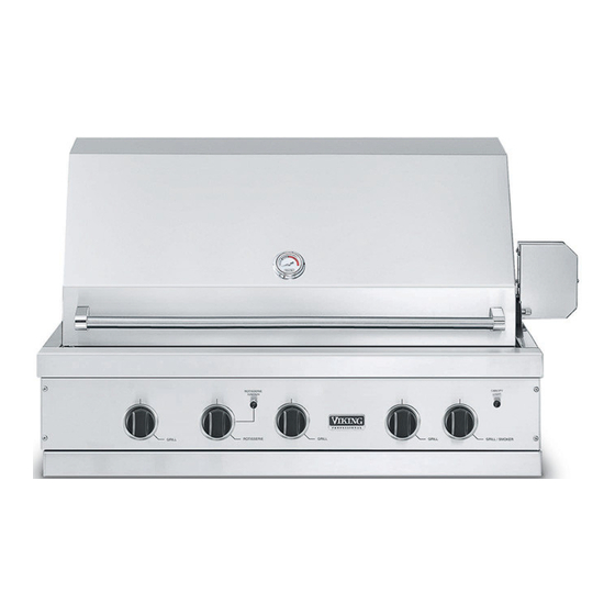
Summary of Contents for Viking NGIQ532T
- Page 1 Viking Installation Guide Viking Range Corporation 111 Front Street Greenwood, Mississippi 38930 USA...
-
Page 2: Important: Please Read And Follow
IMPORTANT: PLEASE READ AND FOLLOW • Before beginning, please read these instructions completely and carefully. • Do not remove permanently affixed labels, warnings, or plates from product. This may void the warranty • Please observe all local and national codes and ordinances. •... -
Page 3: Basic Specifications
BASIC SPECIFICATIONS VG BQ30OT/O302T Description Cutout Width 28 5/8" (72.7 cm) Cutout Depth Cutout Height 29 1/2" Overall Width (74.9cm) Overall Depth Natural: Requirements LP/Propane: Electrical 9 volt DC battery for electronic ignition Requirements 120VAC/60HZ - 24" (61.0 cm) power cord supply cord with 3-prong grounded plug attached to rotisserie motor Grill Burner Rating TilJSea r... - Page 4 BASIC SPECIFICATIONS VGBQ300E Description 28 5/8" Cutout Width (72.7cm) Cutout Depth Cutout Height 29 1/2" Overall Width (74.9cm) Overall Depth ,Sas Natural: Requirements LP/Propane: Electrical 120VAC/60HZ - 3' ( 91.4 cm) power cord supply cord with 3-prong grounded plug attached to grill Requirements 120VAC/d0HZ - 24"...
-
Page 5: Gas Connection
GAS CONNECTION Verify the type of gas supply to be used, either natural or LP, and make sure the marking on the grill rating plate agrees with that of the supply. shut-off valve must be installed in an easily accessible location. or in the absence of local codes, with the National electrical Code, ANSI/NFPA 70 and the National Fuel Code, ANSI Z223.1. -
Page 6: Natural Fixed Piping Connection
DO NOT forget to place the installer supplied gas valve in an accessible location. NOTE: If using a Viking GSH12 flexible hose, remove the 1/2" flare adapter and attach hose to the 7/8" (2.2 cm) male flare on the regulator assembly. -
Page 7: Lp/Propane Fixed Piping Connection
3/8" Male flare adapter Installer supplied gas line with 3/8" female flare adapter or Viking GHS12 arrow points in the direction of the gas @'@@@ 0 installer supplied shut-oF valve must be easily accessible... -
Page 8: Lp/Propan E Tan K Con N Ection
LP/PROPAN E TAN K CON N ECTION Outdoor grills orificed for use with LP/Propane gas come equipped with a high capacity hose/regulator assembly for connection to a standard 20 lb. LP/Propane cylinder equipped with a Type 1, QCC-1 connector. comply with Elastomeric Composite Hose and Couplings for Conducting Propane and Natural Gas, CAN/CGA-8.1 standard or the Theromp/astic Hose and Hose Couplings for Conducting Propane and Natural Gas CAN 1-8.3 standard. -
Page 9: Leak Testing
LEAK TESTING Although all gas connections on the grill are leak tested at the factory prior to shipment, a complete gas tightness check must be performed at the installation clue to possible mishandling in shipment or excessive pressure unknowingly being applied to the unit. - Page 10 INSTALLATION PROCEDURES FOR BUILT-IN INSTALLATION 1. A minimum of 6" (15.2 cm) from the sides, or a minimum of 8" (20.3 cm) from the right side if there is a rotisserie motor, and a minimum of 24" (61.0 cm) from the back must be maintained from the grill above the cookin 9 surface to adjacent vertical combustible construction.
- Page 11 (15.2 cm) o°@@0 MODEL VGBQ300T/0302T VGBQ300E VGIQ300T VGIQ300E VGBQ410T/VGIQ410T VGBQ410E/VGIQ410E VGBQ412T VGBQ412E VGBQ530T/VGIQ530T VGBQ530E/VGIQ530E VGBQ532T/VGIQ532T VGBQ532TNGIQ532T Dim. A 29 1/2" (74.9 cm) 29 1/2" (74.9 cm) 41 3/16" (104.6 cm) 41 3/16" (104.6 cm) 53 3/16" (135.1 cm) 53 3/16" (135.1 cm) - 5 3/8"...
-
Page 12: Cutout Dimensions
CUTOUT DIMENSIONS **Gas Inlet and power cord supply opening can be located anywhere within 5" (12.7 cm) shaded area 36" (91.4 cm) power supply cord to be located on rear wall with a maximum distance of 2' (61.0 cm) beneath solid bottom *'AccessDoors sold separately- refer to access door installation support... -
Page 13: Burner Adjustment
BURNER ADJUSTMENT Each burner is tested and adjusted at the factory prior to shipment; however, variations in the local gas supply may make it necessary to adjust the burners. The flames of the burners (except the rotisserie infrared burner) should be visually checked and compared with Fig. - Page 14 Fig. 3 SIDE BURNERS (If applicable) °O Fig. 4 FLAME HEIGHT SIDE BURNERS (If applicable) 3/8" (.95 cm) Fig. 6 FLAME HEIGHT TruSear BURN ER 1/4" (.64 Air Shutters ° Orifice Fig. 5 FLAME HEIGHT INFRARED BURNER 1/4" (.64 cm)
-
Page 15: Rotisserie System
ROTISSERIE SYSTEM The rotisserie motor is attached to the mounting bracket located on the right side of the grill frame. The rotisserie motor must be electrically grounded in accordance with local codes The skewer for the rotisserie is assembled into the gear box assembly by placing the pointed end into the gear box, and resting the threaded end on the support at the left side of the grill. - Page 16 F20054H (PSO606VR)


Need help?
Do you have a question about the NGIQ532T and is the answer not in the manual?
Questions and answers