Table of Contents
Advertisement
AE8-1384 R5
Section
Safety
Safety Instructions ...................................................2
Safety Icon Explanation ...........................................2
Shock, Fire, or Injury to Persons .............................3
Safety Statements ...................................................3
Overview ..................................................................4
Features ..................................................................4
Application Usage ....................................................4
Part Numbers ..........................................................4
Agency Recognition .................................................4
Product Specifications .............................................4
Mounting ..................................................................4
Terminal Description and Basic Field Wiring ...........4
Dielectric (Hipot) Testing ..........................................5
Operation
Warning Codes ........................................................5
Alert/Lockout Codes ...................................................5
Resetting Alert Codes ..............................................6
© 2016 Emerson Climate Technologies, Inc.
CoreSense
Communications for 20 to 40 Ton
™
Copeland Scroll
Air Conditioning Compressors
™
TABLE OF CONTENTS
Page
Section
Communications ......................................................6
DIP Switch Configuration .........................................7
Jumper Setting ........................................................7
PC Interface Software .............................................7
Service
Field Service ............................................................8
Troubleshooting .......................................................8
Tables
Module Part Numbers ..............................................9
Module Specifications ..............................................9
Accessory Parts .......................................................9
Modbus Map .....................................................10-12
DIP Switch Purpose ...............................................13
LED Flash Code Information ............................13-14
Figures
Terminal Box Wiring Diagrams ..............................15
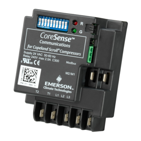
CoreSense Communications Module Photo .......... 16
Thermistor Circuit Cable ........................................16
Modbus Addressing ...............................................17
PC Interface Wiring ...............................................18
1
AE8-1384 R5
August 2016
Page
Advertisement
Table of Contents

Related Manuals for Emerson Copeland CoreSense 571-0065-05

Summary of Contents for Emerson Copeland CoreSense 571-0065-05
-
Page 1: Table Of Contents
Dielectric (Hipot) Testing ..........5 Terminal Box Wiring Diagrams ......15 Operation CoreSense Communications Module Photo ..16 Warning Codes ............5 Thermistor Circuit Cable ........16 Alert/Lockout Codes ...........5 Modbus Addressing ..........17 Resetting Alert Codes ..........6 PC Interface Wiring ..........18 © 2016 Emerson Climate Technologies, Inc. -
Page 2: Safety Instructions
NOTICE NOTICE is used to address practices not related to personal injury. CAUTION, without the safety alert symbol, is used to address practices CAUTION not related to personal injury. © 2016 Emerson Climate Technologies, Inc. -
Page 3: Instructions Pertaining To Risk Of Electrical Shock, Fire, Or Injury To Persons
• Refrigerant compressors must be employed only for their intended use. • install, commission and maintain this equipment. • • All valid standards and codes for installing, servicing, and maintaining electrical and refrigeration equipment must be observed. © 2016 Emerson Climate Technologies, Inc. -
Page 4: Introduction Overview
An explanation of the protection module that may have been previously terminal designations follows: used with Copeland Scroll compressors. T2-T1: Module power supply, 24 or 120/240 VAC. CoreSense Communications modules are not intended L1-L2-L3: Phase inputs corresponding to compressor to be used as field retrofits for other motor protection input power L1-L2-L3. © 2016 Emerson Climate Technologies, Inc. -
Page 5: Dielectric (Hipot) Testing
U.L. sets the requirement for dielectric strength testing when the resistance value is in the normal range. and should be consulted for the appropriate voltage and leakage values. Emerson Climate Technologies Alert/Lockout Codes (Red LED Flash Code) does not recommend hipot testing at voltages higher Code 1 –... -
Page 6: Resetting Alert Codes
A Code 7 Alert will open the M2- the data that resides in the CoreSense Communications M1 contacts. The module will lockout the compressor module. Emerson Climate Technologies Modbus has after one Code 7 Alert. A power cycle or Modbus six message categories: reset command will be required to clear the lockout. -
Page 7: Dip Switch Configuration
PC Interface Software The following steps cover the DIP switch settings throughout the commissioning process for a multiple PC interface software is available from Emerson Climate compressor system with communications. Technologies, Inc. The PC interface software allows the design engineer access to status, configuration, 1. -
Page 8: Field Service
If a compressor with CoreSense Communications fails in the field, the CoreSense module should NOTICE remain with the failed compressor so Emerson technicians can download the CoreSense data In some rare cases communication between the to assist with determining the root cause of master controller and the CoreSense module is compressor failure. -
Page 9: Module Part Numbers
-40° to 150°F (-40° to 65°C) Storage Temperature -60° to 175°F (-51° to 80°C) -60° to 175°F (-51° to 80°C) Table 3 CoreSense Communications Accessory Parts Part Description Part Number Scroll/Motor Thermistor Harness 529-0102-00 © 2016 Emerson Climate Technologies, Inc. -
Page 10: Modbus Map
13 - Motor High Temperature Open OR Short Lockout 14 - Reverse Phase Lockout 15 - Missing Phase Lockout 16 - Scroll High Temperature Lockout 17 - Motor High Temperature Trip Lockout 18 - P47 Module Failure © 2016 Emerson Climate Technologies, Inc. - Page 11 Compressor start history with cumulative count Short Cycle history with cumulative count Unused (30 bytes) Seven day Warning history with cumulative count Seven day Trip history with cumulative count Seven day Lockout history with cumulative count © 2016 Emerson Climate Technologies, Inc.
- Page 12 Scroll High Temp Trip Scroll High Temp Reset No. of Events to Phase Loss Lockout Future Use Future Use Future Use No.of Events to Scroll High Temp Lockout No.of Events to Short Cycling Warning © 2016 Emerson Climate Technologies, Inc.
-
Page 13: Led Flash Code Information
Future Use Future Use Future Use No.of Events to Scroll High Temp Range: 4 to 36 Lockout No.of Events to Short Cycling Warning Range: 20 to 200 Options: 0x0800(Alarm Reset) & Write Command 0x8000(Module Reset) © 2016 Emerson Climate Technologies, Inc. -
Page 14: Dip Switch Purpose
3) Install anti-short cycling control 1) Check for poor connections at module and thermistor fusite Green Open/Shorted Ω > 370K or Ω < 1K 5.1K < Ω < 370K Flash Code 4 Scroll Thermistor 2) Check continuity of thermistor wiring harness Green Future Use Flash Code 5 © 2016 Emerson Climate Technologies, Inc. -
Page 15: Terminal Box Wiring Diagrams
Low voltage on T2-T1 Check VA rating of transformer the voltage is back in Flash Code 9 Voltage terminals 3) Check for blown fuse in the normal range transformer secondary This Alert does not result in a Lockout © 2016 Emerson Climate Technologies, Inc. -
Page 16: Coresense Communications Module Photo
REGLAMENTARIA PARA EL PRODUCTO FINAL SHORT CYCLE PROTECTION / ENABLE / DISABLE / – VEA LA PLACA DE DATOS 02-14 052-2895-00 PROTECCIÓN CONTRA CICLOS CORTOS ACTIVADO DESACTIVADO Figure 1b – ZP236/296 Terminal Box Wiring Diagram © 2016 Emerson Climate Technologies, Inc. - Page 17 View A Scroll NTC Thermistor Motor PTC Thermistor (black wire) (red wire) Common Connection Spare Connection (blue wire) Terminal identification is from the end of the plug (View A) Figure 3 Thermistor Circuit Cable © 2016 Emerson Climate Technologies, Inc.
-
Page 18: Modbus Addressing
= 25 = 15 = 26 = 16 = 27 = 17 = 28 = 18 = 29 = 19 = 30 = 20 = 31 = 10 = 21 Figure 4 Modbus Addressing © 2016 Emerson Climate Technologies, Inc. -
Page 19: Pc Interface Wiring
The contents of this publication are presented for informational purposes only and they are not to be construed as warranties or guarantees, express or implied, regarding the products or services described herein or their use or applicability. Emerson Climate Technologies, Inc. reserves the right to modify the designs or specifications of such products at any time without notice. Emerson Climate Technologies, Inc. does not assume responsibility for the selection, use or maintenance of any product. Responsibility for proper selection, use and maintenance of any Emerson Climate Technologies, Inc. product remains solely with the purchaser and end-user.
Need help?
Do you have a question about the Copeland CoreSense 571-0065-05 and is the answer not in the manual?
Questions and answers