Table of Contents
Advertisement
MINEBEA CO., LTD.
DIGITAL INDICATOR
CSD−814B
Note : Please read this Instruction Manual carefully before use.
Be sure to follow the items that require attention described in the manual.
Keep the manual at hand so that you can pick it up and read it as soon as
necessity requires.
INSTRUCTION
MANUAL
DRW. NO. EN294−1213−F
Advertisement
Table of Contents
Troubleshooting

Related Manuals for Minebea CSD-814B


Summary of Contents for Minebea CSD-814B
- Page 1 MINEBEA CO., LTD. INSTRUCTION MANUAL DIGITAL INDICATOR CSD−814B Note : Please read this Instruction Manual carefully before use. Be sure to follow the items that require attention described in the manual. Keep the manual at hand so that you can pick it up and read it as soon as necessity requires.
- Page 2 FORWARD Thank you very much for your purchasing Minebea’s Digital Indicator CSD−814B. This manual explains installation procedures and connecting method and also operating method for Digital indicator CSD−814B. Make use of it properly after reading through the manual carefully. Be sure to deliver the manual to the end user. Moreover, the end user should keep the manual at hand after reading it over.
- Page 3 Marks and arrangement used in this manual The following marks are attached to the explanation on the matters that indicate “Don’t do this.”, “Take care.” and “For reference”. Be sure to read these items where these marks are attached. ● Warning may cause injury or accident that may harm to the operator. Warning Don’t do these things described here.
- Page 4 For safe operation Be sure to read this manual before use. 1. Installation place ● Use the instrument where the temperature/humidity specifies within the range as follows: : −10 ℃ to 50 ℃ Environmental temperature Environmental humidity : Less than 85 %R.H. Non condensing.) (1) Location where installation is not allowed.
-
Page 5: 1−1. Installation
1−1. Installation ● When installing the instrument, install as referring to the following figures and secure the space around the instrument. Each dimension of the instrument and required dimensions for the environmental spaces are as follows: < Dimensions for installation > Side Front (20.3) -
Page 6: Power Supply
● Before supplying the power, check that the indication of power supply/specification for the instrument and the power going to supply should be the same. If they are not equal, contact with Minebea. If you use the instrument without checking them, it may cause a damage in the instrument or electric shock to the operator. - Page 7 ● Do not shock the instrument such as throwing something on it. Warning It may cause the damage to the case and even have the possibility of damage to the instrument in resisting to environment. ● Do not push the panel sheet on the instrument with unnecessary Warning strong force nor push it with sharp edge object such as driver It may cause a damage to the case or panel sheet and even have the...
-
Page 8: Record Of Revision
A−F, and C−G on the rear panel terminal board. Due to ECN No. FN10−02140 Oct. 2010 DRW. NO EN294−1213−E − Change − Minebea logo is changed Due to ECN No.FN11−02018 − Correction − Jan.2011 DRW. NO EN294−1213−F 9−3−4. “DE−9S−N(JAE)”... -
Page 9: Table Of Contents
CONTENTS Ⅰ FORWARD ............Ⅱ... - Page 10 6−2−2. When pressed with the key together in Measurement mode..6−2−3. When operated in fine adjustment mode for Zero and Span..6−2−4. When operation is made in another mode. .
- Page 11 7−5. Stabilizing filter ........... . . 7−5−1.
- Page 12 9−3−5. Data format ........... 9−4.
- Page 13 11−11−6. Serial interface ..........11−11−7.
-
Page 14: General
1. General The instrument is a digital indicator for the purpose of strain gage applied transducers. 1−1. Features Main features for CSD−814B are shown as follows: (1) Large load display The fluorescent character display tube that specifies 22 mm of character’s height is prepared. (2) Bar meter display Due to the bar meter of 11 DOT, the percentage of present gross weight against the maximum display value can be displayed at the intervals of 10%. -
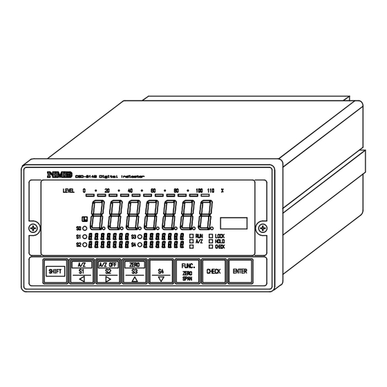
Page 15: Each Name And Function
Each name and function 2−1. Front panel ② ① ⑭ ⑮ ③ ④ ③ ⑧ ⑨ ⑩ ⑥ ⑦ ⑪ ⑫ ⑬ Load display Displays Load data in Measurement mode, and displays status in various kinds of Calibration mode, and in Setting mode. Bar meter display Bar meter of 11 dots that displays the ratio of present Gross weight against the maximum display value at the intervals of 10 %. - Page 16 Used when S1 set value changing mode is required, and also carrying the values at the time of various kinds of set value is required. Also Tare (A/Z) will be executed by pressing the key together. Used when S2 set value changing mode is required, and also when the digit down for the values are required at the time of various kinds of setting is applied.
-
Page 17: 2−2. Rear Panel
2−2. Rear panel Terminal board 1 Make connection with each of external control input “ZERO”, “A/Z”, “A/Z OFF”, “HOLD”, “LOCK”, “A−SEL ”, contact output “RUN”, “S0”, “S1”, “S2”, “S3”, “S4” and “ERROR”. Terminal board 2 Make connection with various kinds of strain gage applied transducer such as load cell, grounding wire and AC power supply. -
Page 18: Installation Procedures
Installation procedures 3−1. Installation place ● Use the instrument where the temperature/humidity specifies within the range as follows: : −10 ℃ to 50 ℃ Environmental temperature : Less than 85 % R.H.(Non condensing.) Environmental humidity 3−2. Location where installation is not allowed. ●... -
Page 19: 3−3. Installation
3−3. Installation ● When installing the instrument, install as referring to the following figures and secure the space around the instrument. Each dimension of the instrument and required dimensions for the environmental spaces are as follows: Side Front (20.3) (46) Rear Panel cut size +... -
Page 20: Connecting Method
Connecting method 4−1. Layout of terminal 2 pieces of terminal boards and M3 screws are prepared on the rear panel of the instrument. Layout of terminal board are shown in the following table. Terminals Terminal No. Name Usage Terminal No. Name Usage ①... -
Page 21: 4−2. Note On Connection
4−2. Note on connection ● In case of connection with the instrument, keep strictly to the Warning following items. If neglected, it may cause an unexpected failure or a damage to the instrument. ・ Set the power supply to OFF when connection is made. ・... -
Page 22: 4−3. Connection
4−3. Connection 4−3−1. Connection with strain gage applied transducers The instrument can connect with strain gage applied transducers, such as load cell, pressure transducer and so on. Here, we will describe the example of connection with load cell, so connect with another strain gage applied transducers with the same way. ※1 When tension is applied with the application of tension type or universal(compression/tension) type load cell, and display of “+”... - Page 23 ※1 When tension is applied with the application of tension type or universal(compression/tension) type load cell, and display of “+” direction is required, connect “green” with Terminal No.22, and “blue” with Terminal No.21. As there is a case which standard wiring color is different, please confirm the inspection data sheet of the load cell being used.
- Page 24 ii) In case of application of CAB−501(6−cores cable) Junction box B−304 CAB−501 ※ ※ ※ ※ 3 (Length of CAB−502 should be within 30 m totally.) B−304 Internal terminal connection To Load cell YEL(Shield) Suitable crimp−type terminal lugs: 1.25−4 or 2−4 Terminal Pitch 9.5 mm YEL(Shield) To CSD−814B...
- Page 25 ※1 When tension is applied with the application of tension type or universal(compression/tension) type load cell, and display of “+” direction is required, connect “green” with Terminal No.22, and “blue” with Terminal No.21. As there is a case which standard wiring color is different, please confirm the inspection data sheet of the load cell being used.
- Page 26 ii) In case of application of CAB−501(6−cores cable) Junction box B−307 CAB−501 ※ ※ ※ ※ 2 (Length of CAB−501 should be within 100 m totally.) B−307 Internal terminal connection 1W 1W 1W 1W 1R 1R 1R 1R 1G 1G 1G 1G 1B 1B 1B 1B YEL(SHIELD YEL(SHIELD)
- Page 27 ※1 When tension is applied with the application of tension type of universal(compression/tension) type load cell, and display of “+” direction is required, connect “green” with Terminal No. 22, and “blue” with Terminal No. 21. As there is a case which standard wiring color is different, please confirm the inspection data sheet of the load cell being used.
- Page 28 ii) In case of application of CAB−501(6−cores cable) CAB−501 ※ ※ ※ ※ 3 (Length of CAB−501 should be within 100 m totally.) SB−310 Internal terminal connection SB−310 Internal terminal connection Short bar Output Point Input Point 1 To CSD−814B WH GN BL YE OR BK WH GN...
-
Page 29: 4−3−2. Connection With External Control Input
4−3−2. Connection with external control input Connection with external control input of “ZERO”, “A/Z”, “A/Z OFF”, “HOLD”, “LOCK” and “A−SEL ” should be used with the contact between each terminal and “COM 1” at terminal No.7, or with the open collector as the following figure indicates. As for the function for each input, refer to the paragraph 7−1. -
Page 30: 4−3−3. Connection With Contact Output
4−3−3. Connection with contact output Connection with contact output “RUN”, “SO”, “S1”, “S2”, “S3”, “S4”, “ERROR” and external load should be made between each terminal and “COM. 2” on terminal No.16 as the following figure. At the same time, take care that the load should not exceed the rated contact of load. Rated load for contact AC125 V 0.1 A DC30 V... -
Page 31: 4−3−4. Connection With Power Supply And Ground
4−3−4. Connection with power supply and ground Connection with power supply and ground should be made as the following figure. Grounding should be the D class with single earth. Power supply voltage AC100 V (AC85 V to AC132 V) Frequency for power supply 50/60 Hz Power consumption Approx. -
Page 32: Calibration Procedure
Calibration procedure ● Before using the new instrument or after exchanging the sensor with Warning new one, be sure to make calibration. If calibration is not made, correct measured results may not be obtained, nor it may cause malfunction to the instrument and it may damage the peripheral equipment. - Page 33 5−2−1. Calibration method to register the output of strain gage applied transducer at the time of maximum display after setting the load to zero(0). ● Before using the new instrument or after exchanging the sensor with Warning new one, be sure to make calibration. If calibration is not made, correct measured results may not be obtained, nor it may cause malfunction to the instrument and it may damage the peripheral equipment.
- Page 34 Procedures Press the key for about one second. Load display will show “FUNC”. Press the key once. Load display will show “CCAL ”. Press the key. CCAL mode can be entered, then the load display will show “D−01” and the digit of 10 will flash on and off.
- Page 35 Procedures Press the key. The load display will become “2000”, and the digit of minimum display will flash on or off. When the calibration has completed, the set value of minimum scale which has registered at that time will be displayed. By the setting of minimum scale, the digit of minimum display that flashes on and off will be as follows:...
- Page 36 Procedures Press the key. The load display will show “0.30000”, then the digit of 10 will flash on and off. In case that calibration has finished, the registered output value for load cell at that time will be shown. Set the output value for load cell corresponding to the maximum display value that has set in step 5 with the right keys.
- Page 37 Procedures Press the key. The load display will show “− − − −” with flashing display on and off, then zero adjustment can be started. : Warning At the same time, take care not to apply load vibration due to vibration and so on.
-
Page 38: 5−2−2. Fine Adjustment Mode
5−2−2. Fine adjustment mode. ● During tare cancellation(A/Z) and zero set is executed, and during zero tracking is effective, fine adjustment mode can’t be entered. (Displays “ERR−5”) ● When HOLD signal is input with the display or with the condition of target of hold(FUNC−50) for option, fine adjustment mode can’t be entered. - Page 39 Procedures Check that the S3 display shows “ZERO”. When the S3 display shows “SPAN”, press the key once. Then, check that S3 display changes to “ZERO”. Adjust the display to “0” with the right keys by the following procedures. Adjust so that the display shows the nearest zero with coarse adjustment keys.
- Page 40 Procedures Set the display to the load value applied at present with the right keys. When more than ±20 % of difference against desired value is found, use the coarse adjustment key for span. In case of less than ±20 % of difference, use fine adjustment keys.
-
Page 41: 5−3. Selection Of Calibration Procedures On Each Condition
・ Loading condition is clear, but output condition for load cell is unclear. To make calibration again. ・ To make calibration on tare weight only. (Combined inspection is executed at Minebea, and calibration is desired only for tare weight.) ・ To execute fine adjustment on Zero and Span. -
Page 42: 5−3−1. To Make Calibration On The Instrument
5−3−1. To make calibration on the instrument. When the new instrument is purchased, or re−use is required with the new specific conditions, execute the calibration with whichever method as follows: When loading condition and output condition for load cell are clear. (In case of desired accuracy is less than 1/1 000 or so.) ●... - Page 43 When loading condition and output condition for load cell are clear. (In case desired accuracy is more than 1/1 000 or so.) ● The accuracy obtained by the calibration of this procedure, consists Warning from combined accuracy with the instrument and combined strain gage applied transducer, the accuracy of weight used in the calibration, error factors on mechanical and also error factors on calibration works, that is total accuracy.
- Page 44 Loading condition is clear, but output condition for load cell is unclear. When existing load detective section is used and only the instrument of digital indicator is used newly, but the output of load cell is unclear, the calibration should be made after checking the output value of load cell.
-
Page 45: 5−3−2. In Case Of Executing Recalibration
5−3−2. In case of executing recalibration. When purchasing the instrument newly, and also executing combined inspection at Minebea, or executing fine adjustment on zero and span, make calibration with whichever method as follows: Calculation on tare weight only. (Combined inspection has completed at Minebea and calibration on tare weight only is required.) -
Page 46: Operating Procedures
Operating Procedures We’ll show the operating procedures for the instrument with each key located on the front panel. ● Operation with each key should be made after interrupting the Warning measurement. If it is made during measurement, it may cause an unexpected malfunction. -
Page 47: 6−2−4. When Operation Is Made In Another Mode
6−2−4. When operation is made in another mode. Carrying set value When the key is pressed with the condition of displaying various kinds of set values, the flashing digit for set value will carry from 10 to 10 , 10 , 10 , 10 , and 10... -
Page 48: 6−3−4. Operation Is Made In Another Mode
6−3−4. Operation is made in another mode. Digit down for set value When the key is pressed with the condition of displaying various kinds of set values, the digit of set value is down towards the digit of 10 of set value one by one. Changeover of function and so on. -
Page 49: 6−5. Key
6−5. key 6−5−1. Press key in the Measurement mode. digit at set vale of comparator S4 will flash, then setting for set value of comparator S4 will be possible. Moreover, if any key operation is not made during 20 s approximately, that is, untouched, the mode will be returned to the measurement mode automatically. -
Page 50: 6−7. Key
6−7. key 6−7−1. When pressed singly in Measurement mode. CHECK value equal to about 0.3 mV/V will be ON and “CHECK” on status display will be lighted and at the same time, equal to about 0.3 mV/V of load value will be added. By pressing again, check value will be OFF, and returns to the status as it was. -
Page 51: Function And Operation
Function and operation 7−1. External control input signal, contact output signal External control can be available through various kinds of input/output signals. 7−1−1. External control input signal Activates by shortening with COM.1(terminal No.7). Terminal No. Name Operation When the display value on load display is within 10% against maximum display value, zero set function will activate and make the display “0”... -
Page 52: 7−1−2. Contact Output Signal
7−1−2. Contact output signal Terminal No. Name Operation When the instrument is in the Measurement mode, connection can be ⑨ available. Open when CHECK is OK. 1a contact. By the setting function FUNC−13, operation can be made in either condition as below: a) Connects when the load display is more than the maximum display ⑩... -
Page 53: 7−2. Comparator
7−2. Comparator The instrument prepares comparator consisting of 4 pieces set values S1, S2, S3, and S4, and also comparator (SO) that can change operation by the setting of Function FUNC−13. ● The comparator in the instrument executes comparative operation Warning and synchronous with load display. - Page 54 Procedures Change S1 set value When the key is pressed in Measurement mode, digit of S1 set value display on front panel will flash, then S1 setting can be changeable. Every time the key is pressed, the flashing digit → digit →...
- Page 55 Procedures Change S3 set value When the key is pressed in Measurement mode, digit of S3 set value display on front panel will flash, then S3 setting can be changeable. Every time the key is pressed the flashing digit → digit →...
-
Page 56: 7−2−2. Operation On Comparator S1, S2, S3 And S4
7−2−2. Operation on comparator S1, S2, S3 and S4 The comparator in the instrument, S1, S2, S3 and S4 individually can select the operation whichever “contact ON at greater than or equal to set value” or “contact ON less than the set value”. -
Page 57: 7−2−3. Comparative Target For Comparator S1, S2, S3 And S4
7−2−3. Comparative target for comparator S1, S2, S3 and S4 The comparator in the instrument, S1, S2, S3 and S4 individually can select the comparative target from “Display”, “Net weight” and “Gross weight”. These selections can be made in Function mode. (Related Function FUNC−11) As for default, “Display”... -
Page 58: 7−2−4. Operation Of Comparator So
7−2−4. Operation of comparator SO The comparator SO in the instrument can select one operation among eight(8) from “000000” to “000007”. These selections can be made in Function mode(Related Function FUNC−13). As for default, “000000” is selected. ● Depending on operational selection for comparator, ON/OFF Warning condition for SO contact output may differ. - Page 59 When both of “Greater than or equal to” is selected for both of S1 and S2 with FUNC−12. ON at (S1 set value) ≦ (Display value) S1 judgement display, S1 contact output ON at (S2 set value) ≦ (Display value) S2 judgement display, S2 contact output ON at (S1 set value) >...
- Page 60 When “Greater than or equal to” is selected for S1 and “Less than or equal to” is selected for S2. ON at (S1 set value) ≦ (Display value) S1 judgement display, S1 contact output ON at (S2 set value) ≧ (Display value) S2 judgement display, S2 contact output S0 judgement display, S0 contact output always OFF...
-
Page 61: 7−2−5. Hysteresis On Comparator
7−2−5. Hysteresis on comparator The comparator S1, S2, S3 and S4 in the instrument can set hysteresis for prevention from chattering at output relay. Hysteresis can be used by the combined setting of data width and time width. Moreover, effective direction for hysteresis can be selected from either “OFF delay” or “ON delay”. These selection can be made in Function mode. - Page 62 When the operation of “contact ON less than or equal to set value” is selected at S1, and effective direction for hysteresis is set as “ON delay”. Hysteresis time width S1 Set value Hysteresis data width Time S1 Judgement display, S1 Contact output When the operation of “contact ON less than or equal to set value”...
-
Page 63: 7−3. How To Use Filter
7−3. How to use filter This instrument prepares digital filter that stabilizes data converted into digital though calibration process. ● When setting filter is not suitable, correct measurement can’t be Warning made and it may cause an unexpected accident, so care should be taken fully. -
Page 64: 7−4. Zero Tracking
7−4. Zero tracking This instrument prepares zero tracking function in order to compensate for slow drift of zero. 7−4−1. What is zero tracking ・ Zero tracking is a function to cancel slow drift of zero within the constant condition, and also to follow the zero point of the instrument in order to stabilize zero point. -
Page 65: 7−4−3. Target Of Zero Tracking
7−4−3. Target of Zero tracking Zero tracking of this instrument can select the target from either “Gross weight” or “Net weight”. This selection is made in Function mode(related Function/FUNC−62). As for default, “gross weight” has set. 7−4−4. Cancellation for compensation by zero tracking. Cancellation for data cancelled by zero tracking can be executed with Function/FUNC−98. -
Page 66: 7−5. Stabilizing Filter
7−5. Stabilizing filter This instrument prepares Stabilizing filter that can filter through digital filter strongly when variable width for load is within the constant value and also when the condition is frozen for more than a constant period. 7−5−1. What is Stabilizing filter? When the variable width of load is within the set value by Function FUNC−09 and also when the condition is frozen for more then the set period set with the FUNC−10, the digital filter for stabilizing filter will become effective set with Function FUNC−09. - Page 67 Load variable Setting of Setting of width FUNC−10 FUNC−10 Load variable width Data width for Data width for Stabilizing filter Stabilizing filter Setting of FUNC−10 Load variable width Data width for Stabilizing filter Time Digital filter for effective Stabilizing filter ineffective...
-
Page 68: 7−6. Various Kinds Of Functions Related With Display
7−6. Various kinds of functions related with display 7−6−1. Selection of target for display on load display The load display for the instrument can select from “Net weight” and “Gross weight”. These selections can be made in Function mode(related Function FUNC−02). As for default, “Net weight”... -
Page 69: 7−6−4. Lighting−Up Conditions For Bar Meter Display
7−6−4. Lighting−up conditions for bar meter display. Lighting−up conditions when “Lights up” is selected in Function FUNC−51 are as follows. Present gross weight values against maximum display value are shown with the ratio. Ratio against maximum Lighting condition display value Less than 0 % or Equal to 0 % All puts off. -
Page 70: 7−6−5. Selection Of Target For Hold
7−6−5. Selection of target for HOLD The instrument can select the target for HOLD function among “Bar meter display, load display”, “Comparator judgement display, contact output” and “Options” by combination. This selection can be made in Function mode(Related Function FUNC−50). As for default, “All is selected”. -
Page 71: 7−6−7. Selection Of "+ Display Mode And "+/− Display Mode
7−6−7. Selection of “+ display mode and “+/− display mode” This instrument prepares modes, that is, one is “+” side display mode for the sensor input of 0 ~3 mV/V , and the other mode is “+/−” both sides display for the sensor input of 0~±3 mV/V . These selections can be made in Function mode. -
Page 72: 7−7. Change Of Bridge Power Supply Voltage
7−7. Change of bridge power supply voltage This instrument can select the bridge power supply voltage among “10 V”, “5 V” and “2.5 V”. This selection has made in Function mode(Related Function FUNC−55). As for default, “10 V” has selected. When CSD−814B is applied for the system where zener barrier is used, apply it by selecting the bridge power supply voltage properly according to the below table. -
Page 73: 7−9. Zero Set
7−9. Zero set The instrument prepares zero set function. When the display value on the load display is less than 10 % against the maximum display value(Refer to the section 5.), the display will become “0” compulsively due to zero set function when the key is pressed with the key pressed together. -
Page 74: 7−11. Check Value
7−11. CHECK value In Measurement mode, when the key is pressed, appropriate to 0.3 mV/V(approx.) check value will be ON, and at the same time when the “CHECK” on the status display lights, appropriate to 0.3 mV/V(approx.) load value will be added to the load display value. By pressing the key again, check value will be OFF, then returns to the status as it was. -
Page 75: 7−14. Check Mode
7−14. Check mode The following checks can be made in the check mode. ・ Confirmation of ROM version. ・ Confirmation on bridge voltage. ・ Confirmation on installed options. ・ Confirmation on control input. ・ Confirmation on contact output. ・ Confirmation on analog output(option). ・... -
Page 76: 7−14−1. Operating Procedures For Check Mode
7−14−1. Operating procedures for check mode ● From the “FUNC” condition on the load display section, the display will change as below in every time the key is pressed. Conversely, every time the key is pressed, the display will change to the opposite direction to the arrow marks. - Page 77 Procedures ・ Confirmation on ROM version Press the key. Check mode can be entered, and load display will show “ROM”. By pressing the key again, ROM version on load display will be appeared. In Check mode, when the display on the load display shows whichever one in below, display can be changed with the key operation of and keys.
- Page 78 Procedures ・ Confirmation on bridge power supply voltage. Press the key. The load display will show “GV” By pressing the key again, bridge power supply voltage that has selected at present will be shown. ・ Confirmation on installed options. Press the key. The load display will show “OP”...
- Page 79 Procedures Confirmation on external control input signal. Press the key. The load display will show “IN”. By pressing the key again, the load display will change to “−IN−”. At the same time, ON/OFF condition of external control input signal can be monitored on the front panel display.
- Page 80 Procedures ・ Confirmation on contact output signal. Press the key. The load display will show “OUT”. By pressing the key again, the load display will change to “−OUT−”. At the same time, each contact output will vary by the key operation in the right figure. “All OFF”...
- Page 81 Procedures ・ Confirmation on analog output When analog output hasn’t installed, skip to step 9. Press the key. The load display will show “A−OUT”. By pressing the key again, load display will change to “LOW”. At the same time, appropriate to “LOW” output can be obtained from the analog output.
- Page 82 Procedures ・ Confirmation on BCD output. When BCD output hasn’t installed, skip to step 10. Press the key. The load display will show “BCD”. By pressing the key again, load display will change to “0” and the digit of 10 will start to flash on and off.
- Page 83 Procedures ・ Confirmation on open collector output for digital interface. When digital interface hasn’t installed, skip to step 11. Press the key. The load display will show “DIGSW” By pressing the key again, the load display will start to flashing on and off. At the same time, each open collector output will vary by the key operations in the right Fig.
-
Page 84: 7−15. Monitor Mode
7−15. Monitor mode In Monitor mode, present load applied on strain gage applied transducer can be calculated into mV/V and displays the value as well. Suppose the output for load cell applied is unknown, apply actual load and then read out the output of load cell when initial load is applied and when maximum load is applied as well by using this function, then make calibration based on the value. - Page 85 Procedures Press the key for about 1 s. The load display will show “FUNC”. Press the key at 3 times. The load display will change from “CCAL ” → “CHECK” → “MONIT” ・ mV/V conversion display for the input of present transducer.
-
Page 86: Function Mode
Function mode ● During the Function mode, the instrument suspends measurement. Warning In due corse, even when input of strain gage applied transducer varies, various kinds of outputs will not vary, that may cause a destroy in equipment due to malfunction in peripheral equipments. ●... - Page 87 Procedures Select the desired Function No. by using the key in the right Fig. Suspend the setting of Function mode, then Measurement mode can be entered by pressing the key. : Set value carry key. : Set value carry key. By pressing the key continuously, : Set value down key.
- Page 88 Procedures Press the key. Setting contents are registered, the load display will return to the Function No. registered. When returning to Measurement mode without registering the setting contents, press the key. When setting another Function No. is desired, return to step 3. Press the key.
-
Page 89: 8−2. Function On Function Data
8−2. Function on Function data ・ FUNC−01 Selection of the position of decimal point display. Initial value = 000000 000000 = Non 000001 = 10 000002 = 10 000003 = 10 000004 = 10 ・ FUNC−02 Selection of the target for display. Initial value =... - Page 90 ・ FUNC−06 Setting key−lock Initial value = 000000 10 digit : key digit : key digit : key digit : key digit : key digit : key ※ Each ,,,, and key can be key−locked individually. Key−lock cancellation is made by setting “0”, and key−lock is made by setting “1”. Moreover,during the key is locked by pressing the key for more than three seconds with the pressed together, the key−lock will be cancelled only once directly after that.
- Page 91 ・ FUNC−10 Setting time width for stabilized filter Initial value = 000020 000000 = Stabilized filter OFF Setting range : 000000 ~ 000999 Unit : 0.01 s Time width of 9.99 s at “000999” setting. ※ Effective only when setting is made between 000001 ~ 000007, with the FUNC−09 and also between 000001 ~...
- Page 92 ・ FUNC−14 Setting data width for comparator hysteresis Initial value = 000000 000000 = Hysteresis data width OFF Setting range : 000000 ~ 000099 Unit : 1 D 99 D data width at “000099” setting ・ FUNC−15 Setting time width for comparator hysteresis Initial value = 000000 000000 = Hysteresis time width OFF Setting range : 000000 ~...
- Page 93 ・ FUNC−21 Selection of output logic for BCD data. (Effective when option is installed.) Initial value = 000000 000000 = Negative logic 000001 = Positive logic ・ FUNC−22 Selection of output logic for BCD Polarity(POL) (Effective when option is installed.) Initial value = 000000 000000 = Negative logic 000001 = Positive logic ・...
- Page 94 ・ FUNC−30 Selection of baud rate for RS−232C and RS−422 (Effective when option is installed.) Initial value = 000000 000000 = 600 bps 000001 = 1 200 bps 000002 = 2 400 bps 000003 = 4 800 bps 000004 = 9 600 bps 000005 = 19 200 bps ・...
- Page 95 ・ FUNC−37 Setting the direction for digital SW interface comparator. (Effective when the option is installed.) Initial value = 000000 0 = Over = Under digit = Comparator S1 digit = Comparator S2 digit = Comparator S3 digit = Comparator S4 ・...
- Page 96 ・ FUNC−50 Selection of target for HOLD Initial value = 000007 000000 = Ineffective in HOLD 000001 = Holds display only. 000002 = Holds only comparator judgement display and contact output. 000003 = Holds with the both conditions of 000001 and 000002 000004 = Holds optional output only.
- Page 97 ・ FUNC−98 Zero clear Compensated data by Zero set function, compensated data by Tare(A/Z) function, and also compensated data by Zero tracking are cancelled. When the key is pressed with “FUNC−98” is displayed, the display shows “ZCLR?” (At the same time display flashes on and off). At this point, press the key when suspending the ZERO Clear is required.
-
Page 98: 8−3. Target For Comparator And Various Kinds Of Optional Outputs
8−3. Target for comparator and various kinds of optional outputs All of the targets for the instrument for comparator, analog output(voltage output, current output), BCD output, output in Stream mode of RS−232C, Digital SW interface comparator are made with the base of initial value as “Gross weight”. When change of these are required, set the following function again referring to the below table. -
Page 99: Options
Options As for options for the instrument, 10 kinds of outputs and interfaces and so on, and 3 kinds of power supply voltage are prepared. Current output [4 mA to 20 mA] CSD814B−P07 Voltage output [0 V to 1 V] CSD814B−P23 Voltage output [0 V to 5 V] CSD814B−P24... -
Page 100: 9−1. Analog Output
9−1. Analog output ● When power ON the instrument with the external HOLD signal Warning shorted, analog output will be as follows : Even when the Display is targeted for HOLD with the FUNC−50, analog output outputs the least value if the target for analog output is set as Display. -
Page 101: 9−1−2. Specifications For Current Output P/N. Csd814B−P07
9−1−2. Specifications for current output P/N. CSD814B−P07 Output Output : DC4 mA to 20 mA Over range : ±8 %(Approx.) of Full Scale Standard : DC4 mA to 20 mA at the display 0 to 2 000 Display : “−OL ” less than or equal to 2.7 mA(approx.) : “OL ”... -
Page 102: 9−1−5. Specification For Voltage Output P/N. Csd814B−P25
9−1−5. Specification for voltage output P/N. CSD814B−P25 Output Output : DC0 V to 10 V Over range : ±8 %(Approx.) of Full Scale Standard : DC0 V to 10 V at the display 0 to 2 000 Display : “−OL ” less than or equal to −0.8 V(approx.) : “OL ”... -
Page 103: 9−1−7. Scaling Of Analog Output
9−1−7. Scaling of analog output Analog output for standard specifications is set between the minimum value and the maximum value with the range of 0 ~ 2 000. By changing FUNC−17 and FUNC−18, optional value can be decided. Analog Output Maximum value +8 % Maximum value Minimum value... -
Page 104: 9−1−8. Absolute Value Output
9−1−8. Absolute value output When net weight is selected for output data, output can be applied even to the (−) side of display depending on the A−SEL signal condition on the rear panel terminal board by setting “1” on FUNC−19. (+... -
Page 105: 9−1−9. Fine Adjustment 1 On Analog Output
9−1−9. Fine adjustment 1 on analog output Fine adjustment described here, is the one to arrange “the minimum value” and “the maximum value” without applying actual load during the procedures. Refer to the paragraph 9−1−10. as for the fine adjustment with actual load applied. ●... - Page 106 Procedures ・ Fine adjustment on the minimum value for analog output. Press the key. VCAL mode can be entered, then the load display will show “A−LOW”. By pressing the key again, the load display will start to flashing. At the same time, analog output corresponding to the minimum analog output value will output.
- Page 107 Procedures Press the key. The load display shows “A−END”. By pressing the key again, quits the VCAL mode and returns to Measurement mode, then the load value displays. At the same time, result of fine adjustment on the minimum/the maximum analog output value will be renewed.
-
Page 108: 9−1−10. Fine Adjustment 2 On Analog Output
9−1−10. Fine adjustment 2 on analog output Fine adjustment described here is the one to apply actual load during the procedures. ● Before applying this fine adjustment, execute the scaling for analog Warning output according to the paragraph 9−1−7. If neglected, there may be the case that fine adjustment doesn’t succeed to adjust the difference in output. - Page 109 Procedures Fine adjustment on zero at analog output. Press the key. VADJST mode can be entered, then load display will show “A−ZERO”. By pressing the key again, the load display begins flashing the present load and outputs the analog output together. Adjust the deviation of analog output against load with the right keys.
- Page 110 Procedure Press the key. The load display will show “A−END”. By pressing the key again, VADJST mode is over and returns to the Measurement mode and the load will be indicated. At the same time, the result from fine adjustment on analog output will be renewed.
-
Page 111: 9−2. Bcd Output
9−2. BCD output ● When power ON the instrument with the external HOLD signal Warning shorted, BCD output will be as follows: Even when the Display is targeted for HOLD with the FUNC−50, BCD output outputs “000000” if the target for BCD output is set as Display. -
Page 112: 9−2−2. Specifications For Bcd Output
9−2−2. Specifications for BCD output Output Logic Related function Changeover of negative logic and Positive logic can be made with the FUNC−21, FUNC−22, FUNC−23 and FUNC−25. Output data 6 digits parallel output. POL(Polarity) Output ON at minus and output OFF at plus. P .C. -
Page 113: 9−2−3. Pin Configuration For Bcd Output Connector
9−2−3. Pin configuration for BCD output connector 1×10 1×10 2×10 2×10 4×10 4×10 8×10 8×10 1×10 N.C. 2×10 N.C. 4×10 N.C. 8×10 N.C. 1×10 N.C. 2×10 N.C. 4×10 N.C. 8×10 SEL. 1 1×10 D.P .10 2×10 D.P .10 4×10 D.P .10 8×10 D.P .10 1×10... -
Page 114: 9−2−5. Timing Chart
9−2−5. Timing chart Normal 20 times/s : Approx. 50 ms 4 times/s : Approx. 250 ms DATA POL. 20 times/s : Approx. 25 ms 4 times/s : Approx. 25 ms/125 ms changeable P .C. ● At the time of data output each of P .C., DATA and POL, output transistor will become ON. -
Page 115: 9−2−6. Output Condition
When HOLD signal is input HOLD DATA POL. P.C. ● At the time of HOLD signal input, output transistor for P .C. will be OFF condition(Positive logic electrically). However, as for P .C., OFF condition is made after one(1) shot of operation is finished. -
Page 116: 9−3. Rs−232C Interface
9−3. RS−232C Interface ● By feeding ON the instrument with external HOLD signal shorted, Warning the output of RS−232C Interface will be as follows: Even when the Display is targeted for HOLD with the FUNC−50, the load weighing data will become only spaces at the time of reading−out command for load weighing data is executed. -
Page 117: 9−3−2. Specifications For Interface
9−3−2. Specifications for interface Method Corresponds to RS−232C. Specifications for signal Baud rate : 600, 1 200, 2 400, 4 800, 9 600, 19 200 bps Data bit length : 7 bits, 8 bits Parity bit : Non, Even, Odd Stop bit : 1 bit, 2 bits Terminator... -
Page 118: 9−3−4. Pin Configuration For Connector And Connections
9−3−4. Pin configuration for connector and connections Pin configurations ※ Not attached.) Suitable plug : DE−9S−NR by JAE or equivalent. Pin No. Signal Name N.C. S.G. N.C. N.C. Connecting example for RS−232C interface section. EX−1 CSD−814B Host(25 pin) F.G. N.C. S.G. -
Page 119: 9−3−5. Data Format
9−3−5. Data format Stream Mode Load data Sign for load weighing data ・ Load weighing data enters from the right. ・ When the data is minus, “−” sign and when plus, “+” sign is added. ・ Load weighing data performs zero suppress. ・... - Page 120 Command mode Reading−out load weighing data(Host → CSD−814B) Command No. Operation Reading−out Display Data Reading−out Net Weight Command Number Reading−out Gross Weight Reading−out Tare Weight Return ( CSD−814B → Host ) Load weighing data Sign for load weighing data Command No. ・...
- Page 121 Comparative set value Sign for comparative set value Command No. ・ Load weighing data enters from the right. ・ When the data is minus, “−” sign and when plus, “+” sign is added. ・ Comparative set value doesn’t perform zero suppress. ・...
- Page 122 Writing comparative set value(Host → CSD−814B) Comparative set value Sign for comparative set value Command number Command No. Operation Writing S1 setting Writing S2 setting Writing S3 setting Writing S4 setting Comparative set value Sign for comparative set value Command number ・...
-
Page 123: 9−4. Rs−422 Interface
9−4. RS−422 Interface ● By feeding ON the instrument with external HOLD signal shorted , Warning the output of RS−422 Interface will be as follows: Even when the Display is targeted for HOLD with the FUNC−50, the load weighing data will become only spaces at the time of reading−out command for load weighing data is executed. -
Page 124: 9−4−3. Procedures Of Data Transfer
9−4−2. Specifications for Interface Method Corresponds to RS−422. Specifications for Signal Baud rate : 600, 1 200, 2 400, 4 800, 9 600, 19 200 bps Data bit length : 7 bits, 8 bits Parity bit : Non, Even, Odd Stop bit : 1 bit, 2 bits Terminator... -
Page 125: 9−4−4. Pin Configuration On Terminal Board And Their Connections
9−4−4. Pin configuration on terminal board and their connections Pin configuration Differential output(+) Differential output(−) Differential input(+) Differential input(−) Cable end resistance S.G. Signal ground Connecting Example 1 1 vs 1 CSD−814B Host ● For the connections between the instruments, twisted pair wire is recommended. - Page 126 CSD−814B CSD−814B CSD−814B CSD−814B Host ● When connecting with even number sets of CSD−814B, set with FUNC−33 not to have the same ID number(different number) for every set of CSD−814B.
-
Page 127: 9−4−5. Data Format
9−4−5. Data format Command Mode Reading−out load weighing data(Host → CSD−814B) Command No. Operation Reading−out Display Data Reading−out Net Weight Command Number Reading−out Gross Weight ID Code Reading−out Tare Weight (0 to 9 : Set value for FUNC−33) Return ( CSD−814B → Host ) Load weighing data Sign for load weighing data Command No. - Page 128 Reading−out of S3 data Reading−out of S4 data Return ( CSD−814B → Host ) Comparative set value Sign for Comparative set value Command No. ID Code ・ Load weighing data enters from the right. ・ When the data is minus, “−” sign and when plus, “+” sign is added. ・...
- Page 129 ID Code Condition “1” = ON, “0” = OFF “0” ERROR “1” = ON, “0” = OFF “0” Writing comparative set value(Host → CSD−814B) Comparative set value Sign for comparative set value Command number ID Code Command No. Operation (0 to 9 : Set value for FUNC−33) Writing S1 setting Writing S2 setting Writing S3 setting...
- Page 130 Return ( CSD−814B → Host ) ID Code Command Number Error code Error message for command(CSD−814B → Host) Error Code Command number when receiving ID Code...
-
Page 131: 9−5. Serial Interface
9−5. Serial interface ● By feeding On the instrument with external HOLD signal shorted, Warning output of serial interface will be as follows: Even when the Display is targeted for HOLD with the FUNC−50, the load weighing data for the output format of serial interface will become zero(0) at the time of selection of Stream among the output types of serial interface. -
Page 132: 9−5−3. Connecting Method And Internal Equivalent Circuit
9−5−3. Connecting method and internal equivalent circuit Corresponding instruments CSD−814B to serial interface ● Corresponding instrument for serial interface, there are M250 Printer made by UNIPULSE Corporation and so on. ● As for cable, be sure to use 2−cores shielded wire as much as you can. When shielded wire is not applied, make the cable twisted.(Cable length is within 100 m when shielded wire is applied, and within 20 m when shielded wire isn’t applied.) - Page 133 9−5−4. Data format INTERVAL LEN FUN1 FUN2 ST1 INTERVAL Mark signal for more than 15 bits(25 ms) F1~F2 OFF code FUN1 Print command FUN2 00H code 00H code 00H code 00H code 00H code Condition G1~G3 GROSS data N1~N3 NET data Calculated result from LEN to N3 FUN1 Print command...
-
Page 134: 9−5−5. Explanation Of Format Data
9−5−5. Explanation of format data Automatic printing bit [ FUN1 : bit 0 ] This bit is applied for trigger through the receiving instrument for serial interface. Bit for display target [ ST1 : bit 7, bit 6 ] bit 7 : Set as “1”... -
Page 135: 9−6. Digi−Switch Interface
9−6. Digi−Switch Interface By the connection with Digi−Switch externally, 6 digits setting value and polarity for 4 steps comparator can be set. Moreover, compared result for the setting of Digi−Switch will be outputted through open collector. 9−6−1. Related function Operational condition for FUNC−24 ON delay, OFF delay comparator hysteresis. - Page 136 9−6−3. Connector pin configuration for Digi−Switch interface. S1 10 S3 10 S1 10 S3 10 S1 10 S3 10 COM. S1 10 S3 POL. N.C. S1 10 S4 10 N.C. S1 10 S4 10 N.C. S1 POL. S4 10 N.C. S2 10 S4 10 N.C.
- Page 137 9−6−5. Equivalent circuit for input/output. (2) Equivalent circuit for output section (1) Equivalent circuit for input/output Approx. 12 V 2.2 kΩ INPUT 0.047 μ INPUT 430 Ω V V V V =DC30 V V V V =DC30 =DC30 =DC30 I I I I =DC30 =DC30 =DC30...
-
Page 138: 9−6−8. Operation Of Digi−Switch Interface S1, S2, S3 And S4
9−6−8. Operation of Digi−Switch interface S1, S2, S3 and S4 Optional comparator S1, S2, S3 and S4 each can select whichever operation of “Open collector ON at greater than or equal to set value” or “Open collector ON at less than or equal to set value”. -
Page 139: 9−6−9. Comparative Target For Digi−Switch Interface S1, S2, S3 And S4
9−6−9. Comparative target for Digi−Switch interface S1, S2, S3 and S4 Each optional comparator S1, S2, S3 and S4 can select the target for comparison among “Display”, “Net Weight” and “Gross Weight”. These selections can be made in Function mode(Related Function FUNC−36). As for default, S1, S3, S3 and S4 each has selected “Display”. -
Page 140: 9−6−10. Operation Of Comparator S0
9−6−10. Operation of comparator S0 The comparator S0 in the instrument can select eight(8) operations as shown in the paragraph 7−2−4 when installing this option. However, external 4 steps S1, S2, S3 and S4 , will not be operational target for SO when 8 step mode is selected, so care should be taken. 9−6−11. - Page 141 When operation of “Open collector ON at greater than or equal to set value” is selected and “OFF delay” is selected for hysteresis effective width with S1. Hysteresis time width S1 setting value Hysteresis data width Time S1 judgement display S1 open collector output.
-
Page 142: 9−6−12. Prohibition Against Reading Digi−Switch
When operation of “Open collector ON at less than or equal to set value“ is selected and “OFF delay” is selected for hysteresis direction with S1. Hysteresis time width Hysteresis data width S1 setting value Time S1 judgement display S1 open collector output. 9−6−12. -
Page 143: 9−7. Power Supply Voltage Ac200 V(Csd814B−P63)
9−7. Power supply voltage AC200 V(CSD814B−P63) 9−7−1. Layout of terminals 2 pieces of terminals on which 16 places of terminal points are prepared on the rear panel of the instrument. Layout of terminals whose power supply voltage specifies AC200 V shall be shown in the below table. -
Page 144: 9−7−2. Connection With Power Supply And The Ground
9−7−2. Connection with power supply and the ground Connection with power supply and the ground should be made according to the following figure. Grounding should be the D class single type. Power Supply voltage : AC200 V (AC170 V to AC264 V) Power supply frequency : 50/60 Hz Power consumption : Approx. -
Page 145: Troubleshooting
Troubleshooting When abnormal point is found during the operation of the instrument, check the following procedures. However, when applicable item can’t be found, nor symptom of trouble can’t be solved, contact with Minebea Co., Ltd. Supply power again Operation Abnormal operation... -
Page 146: 10−1. Executing Trouble Shooting
Comparator operation is wrong. Contact output doesn’t operate. External control input doesn’t operate. Connecting method is good. Key operation doesn’t work. Another option exists? Check on options Inform Minebea about the contents of failure and situation at site in details. - Page 147 HOLD of BCD output When HOLD is is used. shorted at the time of feeding power, no display. Replace fuse by Fuse is broken. referring to the paragraph 13−1. Inform Minebea about the contents of failure and situation at site in details.
- Page 148 Failure in customer’s input circuit. Confirm the contact output signal by referring to the paragraph 7−13 Check mode. Connect securely according to the Connecting method is good. paragraph 4−3−3 and 7−1−2. Inform Minebea about the contents of failure and situation at site in details.
- Page 149 Connect securely according to the Connecting method is good. paragraph 4−3−3 and 7−1−2. Either the HOLD of Make the HOLD input open. external input or BCD output is use. Inform Minebea about the contents of failure and situation at site in details.
- Page 150 Either the HOLD of Set the HOLD input open. external input or BCD output is used. Connect securely according to the paragraph 4−3−2. Connecting method is good. and 7−1−1. Inform Minebea about the contents of failure and situation at site in details.
- Page 151 Key lock has set with Cancel the key−lock with Function Function FUNC−06. FUNC−06. Either the HOLD of Set the HOLD input open. external control input or BCD output is used. Inform Minebea about the contents of failure and situation at site in details.
- Page 152 Set the connecting range to DC ・ V for the measuring instrument such as tester and so on. The voltage between Inform Minebea about the contents of A and C is same as the setting failure and situation at site in details.
- Page 153 Set the connecting range to DC ・ V for the measuring instrument such as tester and so on. The voltage between Inform Minebea about the contents of A and C is same as the setting failure and situation at site in details.
- Page 154 Set the connecting range to DC ・ V for the measuring instrument such as tester and so on. The voltage between Inform Minebea about the contents of A and C is stable and same as failure and situation at site in details.
- Page 155 Current output is wrong. Voltage output is wrong. BCD output is wrong. RS−232C is wrong. RS−422 is wrong. Serial interface is wrong. Digital switch interface is wrong. Inform Minebea about the contents of failure and situation at site in details.
- Page 156 8. Function mode Setting is correct. and the paragraph 9−1. Either the HOLD of external control input or Set the HOLD input open. BCD output is used. Inform Minebea about the contents of failure and situation at site in details.
- Page 157 Refer to the section 8. Function Setting is correct. Mode and the paragraph 9−1. Either the HOLD of external control input or Set the HOLD input open. BCD output is used. Inform Minebea about the contents of failure and situation at site in details.
- Page 158 Intended value ・ FUNC−20 Selection of the target of doesn’t output. BCD output. (Refer to 8. Function Mode) BCD output Set the HOLD input open. doesn’t vary. Inform Minebea about the contents of failure and situation at site in details.
- Page 159 ・ FUNC−28 Selection of output target in are not transmitted in the Stream Mode. Stream mode. (Refer to the section 8. Function Mode and the paragraph 9−3. RS−232C Interface.) Inform Minebea about the contents of failure and situation at site in details.
- Page 160 Intended values ・ FUNC−28 Selection of output target in are not transmitted in Stream Mode. Stream mode. (Refer to the section 8. Function mode and the paragraph 9−4.) Inform Minebea about the contents of failure and situation at site in details.
- Page 161 (print) ・ FUNC−27 Selection on Operation is wrong. Mode. (Refer to the section 8. Function mode and the paragraph 9−5. ) Inform Minebea about the contents of failure and situation at site in details.
- Page 162 Confirm the contact output signal and open collector output signal in the Check Mode in the paragraph 7−14. Connecting Connect securely according to the method is good. paragraph 4−3−3, 7−1−2 and 9−6−3. Inform Minebea about the contents of failure and situation at site in details.
-
Page 163: 10−2. Error Display
Press the key. Measurement mode can be entered. (This time, A/Z data becomes initial value.) If the Error display shows every time when power is ON, contact with Minebea. HCAL Initial calibration has not completed or Contact with Minebea. initial data has broken. -
Page 164: Specifications
・ A/D sampling 100 times/s ・ CHECK Approx. 0.3 mV/V 1 point ※ Suitable Extension cable is Minebea’s standard cable CAB−501 (6−cores) within 100 m ※ Not applicable when Zener barrier is used. 11−2. Specifications for digital ・ Load display −1 000 to 11 000(×2, ×5 and ×10 can be available.) -
Page 165: 11−3. Function Of Sheet Key On Front Panel
11−3. Function of sheet key on front panel Shift key Set value digit carry/S1 setting display/Tare weight cancellation Set value digit down/S2 setting display/Tare weight cancellation Set value increment/S3 setting display/Zero compensation Set value decrement/S4 setting display Changeover of Function mode/Changeover of ZERO & SPAN adjustment. Changeover of check value Entry key 11−4. -
Page 166: 11−5. Comparator Function
11−5. Comparator function ・ Set value −999 999 to + 999 999 ・ Number of set value4 points of S1, S2, S3 and S4 ・ Set value of Hysteresis data 0 to 99 digits.(Each set value ×2, ×5 and ×10 at the time of increment setting.) ・... -
Page 167: 11−8. General Specifications
11−8. General Specifications ・ Operation temperature/humidity range −10 ℃ to 50 ℃ Temperature Humidity Less than 85 %RH(Non condensing) ・ Power supply voltage AC100 V (AC85 V to AC132 V) ・ Power supply frequency 50/60 Hz ・ Power consumption Approx. 22 VA (at AC100 V without option) Approx. -
Page 168: 11−11. Options
11−11. Options 11−11−1. Current output ・ P/N CSD814B−P07 ・ Specifications Output DC4 mA to 20 mA 510 Ω or less Load resistance Non−Linearity 0.05 %F.S. Less than approx. −8 %F.S. and more than approx. +8 %F.S Over range 11−11−2. Voltage output ・... -
Page 169: 11−11−6. Serial Interface
11−11−4. RS−232C Interface ・ P/N CSD814B−P74 ・ Specifications Baud rate : Select among 600, 1 200, 2 400, 4 800, 9 600 and 19 200 bps. Data bit length : Select from 7 bits and 8 bits. Parity bit : Select from Non, Even and Odd. Stop bit : Select from 1 bit and 2 bits. -
Page 170: 11−11−8. Power Supply Voltage
11−11−7. Digi−Switch interface ・ P/N CSD814B−P78 ・ Specifications 6 digits set value at 4 steps of comparator and polarity can be set with the Digi−switch which connected externally. Input ・ 6 digits Digi−switch of code type ×4 steps and each step of polarity switch(S1, S2, S3, S4) ※... -
Page 171: 11−11−9. Combination With Options
11−11−9. Combination with options × × × × ◯ ◯ ◯ ◯ ◯ − × × × × ◯ ◯ ◯ ◯ ◯ − × × × × ◯ ◯ ◯ ◯ ◯ − × × × × ◯ ◯ ◯... -
Page 172: Warranty
10. Trouble− shooting. Especially, make checks whether the connections of sensor are disconnected or cut off. After that, still there may be found some defects in the instrument, contact with Minebea’s sales office or sales agency from which you have purchased. -
Page 173: Appendix
Appendix 13−1. Replacement of fuse ● When installation method for the fuse is wrong and/or capacity of Warning installed fuse is inadequate, it causes an unexpected faulty of the instrument. Set OFF the power supply for the instrument. Remove the 7 pieces of screws on the rear panel. Toothed lock washers 2−+Cross recessed binding head screw M3 ×... - Page 174 Connector Connector After the connector is removed according to ③, draw out the rear panel from the case further. And replace the fuse installed on the lower side of P .C. board. Lower side P .C. board Time lag fuse 1 A After replacing the fuse, insert the rear panel into the case.
- Page 175 Connector Connector 2−+Cross recessed Toothed lock washers binding head screw M3 × 15 Spring washer +Cross recessed pan head screw M3 × 10 4−+Cross recessed pan head screw M3 × 6...
-
Page 176: 13−2. Character's Pattern For Display
13−2. Character’s pattern for display The following is the table to show display pattern used at 7 segment display on the instrument. -
Page 177: 13−3. Sample Program
Sample program for RS−232C Stream mode. 1000 ' 1010 ’--------------------------------------------- 1020 'CSD−814B Sample program for RS−232C Interface. 1030 'Minebea Co., Ltd. Measuring Components Div. 1040 ’--------------------------------------------- 1050 ' 1060 'This sample is to be used for Stream mode. 1070 CLS 1080 '----------<Port declaration>--------------... -
Page 178: 13−3−2. Sample Program For Command Mode
Sample program for Command mode 1000 ' 1010 '--------------------------------------------- 1020 'CSD−814B Sample program for RS−232C Interface. 1030 'Minebea Co., Ltd. Measuring Components Div. 1040 '--------------------------------------------- 1050 ' 1060 'This sample is to be used for Command mode. 1070 CLS 1080 '----------<Command Definitions>------------... - Page 179 1330 PRINT #1, TXD$(4) : ’Reading out S1 set value 1340 LINE INPUT #1, B$ 1350 E$ = MID$(B$, 1, 1) 1360 IF E$ = “E” THEN 1330 1370 W$ = MID$(B$, 5, 8) : PRINT “Gross Weight = “ ; W$ 1380 ' 1390 print #1, txd$(8) : ’A/Z...
- Page 180 1000 ' 1010 '--------------------------------------------- 1020 'CSD−814B Sample program for RS−422 1030 'Minebea Co., Ltd. Measuring Components Div. 1040 '--------------------------------------------- 1050 ' 1060 'Transfers data to ID0 and ID2 orderly. 1070 'It is decided as “Time−out” when the data is not returned within 3 s after transferring command.
- Page 181 1320 EC = 0 : ’ Error counter 1330 ’ 1340 ’----< Data transfer >---------------- 1350 FOR JJ = 1 TO 2500 : JJ = JJ : NEXT JJ 1360 SW = 0 : EC = 0 1370 PRINT : PRINT INX$(S) 1380 A$ = TXD$(S) 1390 PRINT #1, A$ 1400 PRINT “...
- Page 182 1660 EE = EE + 1 : BEEP 1670 ' 1680 PRINT “Errpr Count = “; EE 1690 PRINT 1700 '------------------< Command transfer, again. >----------- 1710 GOTO 1340 1720 ' 1730 ’ 1740 '============================================= 1750 'Reading RS data 1760 '============================================= 1770 COM STOP 1780 TT$ = time$ 1790 '...
- Page 183 D The contents of this manual may subject to change without notice. MINEBEA CO., LTD Manufacturer HEAD PLANT : 4106−73 Miyota, Miyota−machi, Kitasaku−gun, Nagano, 389−0293 Japan. 81−267−32−2200 .81−267−31−1330 Measuring Components Business Unit FUJISAWA PLANT : 1−1−1, Katase, Fujisawa−shi, Kanagawa, 251−8531 Japan.
Need help?
Do you have a question about the CSD-814B and is the answer not in the manual?
Questions and answers