Sign In
Upload
Manuals
Brands
Minebea Manuals
Measuring Instruments
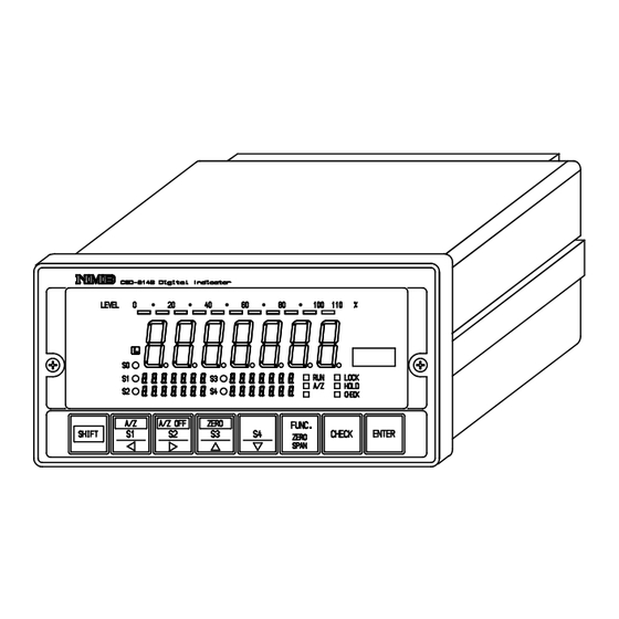
CSD-814B
Minebea CSD-814B Manuals
Manuals and User Guides for Minebea CSD-814B. We have
1
Minebea CSD-814B manual available for free PDF download: Instruction Manual
Minebea CSD-814B Instruction Manual (183 pages)
Digital Indicator
Brand:
Minebea
| Category:
Measuring Instruments
| Size: 4 MB
Table of Contents
1β1. Installation
5
Power Supply
6
Application Notes
6
Record of Revision
8
Table of Contents
9
General
14
1β1. Features
14
Each Name and Function
15
2β1. Front Panel
15
2β2. Rear Panel
17
Installation Procedures
18
3β1. Installation Place
18
3β2. Location Where Installation Is Not Allowed
18
3β3. Installation
19
Connecting Method
20
4β1. Layout of Terminal
20
4β2. Note on Connection
21
4β3. Connection
22
4β3β1. Connection with Strain Gage Applied Transducers
22
4β3β2. Connection with External Control Input
29
4β3β3. Connection with Contact Output
30
4β3β4. Connection with Power Supply and Ground
31
4β3β5. Connection with Options
31
Calibration Procedure
32
5β1. Preparations
32
5β2. Calibration Procedures
32
5β2β2. Fine Adjustment Mode
38
5β3. Selection of Calibration Procedures on each Condition
41
5β3β1. to Make Calibration on the Instrument
42
5β3β2. in Case of Executing Recalibration
45
Operating Procedures
46
6β1. Key
46
Simultaneously in Measurement Mode
46
For Comparator S1, S2, S3, and S4
46
6β2. Key
46
6β2β1. Single Key Is Pressed in Measurement Mode
46
6β2β2. When Pressed with the Key Together in Measurement Mode
46
6β2β3. When Operated in Fine Adjustment Mode for Zero and Span
46
6β2β4. When Operation Is Made in Another Mode
47
6β3. Key
47
6β3β1. Single Key Is Pressed in Measurement Mode
47
6β3β2. When Pressed with the Key Together in Measurement Mode
47
6β3β3. When Operated in Fine Adjustment Mode for ZERO and SPAN
47
6β3β4. Operation Is Made in Another Mode
48
6β4. Key
48
6β4β1. Single Key Is Pressed in Measurement Mode
48
6β4β2. When Pressed with the Key Together in Measurement Mode
48
6β4β3. When Operated in Fine Adjustment Mode for ZERO and SPAN
48
6β4β4. When Operation Is Made in the Other Mode
48
6β5. Key
49
6β5β1. Press Key in the Measurement Mode
49
6β5β2. When Operated in Fine Adjustment Mode for ZERO and SPAN
49
6β5β3. When Operation Is Made in the Other Mode
49
6β6. Key
49
6β6β1. When Pressed in Measurement Mode
49
6β6β2. When Operated in the Fine Adjustment Mode for ZERO and SPAN
49
6β6β3. When Operation Is Made in the Other Mode
49
6β7. Key
50
6β7β1. When Pressed Singly in Measurement Mode
50
6β7β2. When Pressed with the Key Together in Measurement Mode
50
6β7β3. Pressed in the Fine Adjustment for ZERO and SPAN
50
6β7β4. When Operation Is Made in Another Mode
50
6β8. Key
50
Function and Operation
51
7β1. External Control Input Signal, Contact Output Signal
51
7β1β1. External Control Input Signal
51
7β1β2. Contact Output Signal
52
7β1β3. Equivalent Circuit
52
7β2. Comparator
53
7β2β1. Change of Set Value
53
7β2β2. Operation on Comparator S1, S2, S3 and S4
56
7β2β3. Comparative Target for Comparator S1, S2, S3 and S4
57
7β2β4. Operation of Comparator so
58
7β2β5. Hysteresis on Comparator
61
7β3. How to Use Filter
63
7β3β1. Digital Filter
63
7β4. Zero Tracking
64
7β4β1. What Is Zero Tracking
64
7β4β2. Setting Related with Zero Tracking
64
7β4β3. Target of Zero Tracking
65
7β4β4. Cancellation for Compensation by Zero Tracking
65
7β5. Stabilizing Filter
66
7β5β1. What Is Stabilizing Filter
66
7β5β2. Setting Related with Stabilizing Filter
66
7β6. Various Kinds of Functions Related with Display
68
7β6β1. Selection of Target for Display on Load Display
68
7β6β2. Lighting Up/Putting off Comparator Set Value
68
7β6β3. Lighting up / Putting off Bar Meter Display
68
7β6β4. LightingβUp Conditions for Bar Meter Display
69
7β6β5. Selection of Target for HOLD
70
7β6β6. Display Range for Load
70
7β6β7. Selection of "οΌ Display Mode and "οΌ/β Display Mode
71
7β6β8. Selection of ON/OFF for "RUN" Indicator
71
7β7. Change of Bridge Power Supply Voltage
72
7β8. Tare (A/Z)
72
7β9. Zero Set
73
7β10. Key Lock
73
7β11. CHECK Value
74
7β12. Short at the Input of Strain Gage Applied Transducers
74
7β13. Recording Location for Setting Data and so on
74
7β14. Check Mode
75
7β14β1. Operating Procedures for Check Mode
76
7β15. Monitor Mode
84
Function Mode
86
8β1. Setting Method for Function Mode
86
8β2. Function on Function Data
89
8β3. Target for Comparator and Various Kinds of Optional Outputs
98
Options
99
9β1. Analog Output
100
9β1β2. Specifications for Current Output P/N. CSD814BβP07
101
9β1β3. Specifications for Voltage Output P/N. CSD814BβP23
101
9β1β4. Specifications for Voltage Output P/N. CSD814BβP24
101
9β1β5. Specification for Voltage Output P/N. CSD814BβP25
102
9β1β6. Specifications for Voltage Output P/N. CSD814BβP26
102
9β1β7. Scaling of Analog Output
103
9β1β8. Absolute Value Output
104
9β1β9. Fine Adjustment 1 on Analog Output
105
9β1β10. Fine Adjustment 2 on Analog Output
108
9β2. BCD Output
111
9β2β1. Related Functions
111
9β2β2. Specifications for BCD Output
112
9β2β3. Pin Configuration for BCD Output Connector
113
9β2β4. Equivalent Circuit for Input/Output
113
9β2β5. Timing Chart
114
9β2β6. Output Condition
115
9β3. RSβ232C Interface
116
9β3β2. Specifications for Interface
117
9β3β3. Procedures of Data Transfer
117
9β3β4. Pin Configuration for Connector and Connections
118
9β3β5. Data Format
119
9β4. RSβ422 Interface
123
9β4β1. Related Functions
123
9β4β3. Procedures of Data Transfer
124
9β4β4. Pin Configuration on Terminal Board and Their Connections
125
9β4β5. Data Format
127
9β5. Serial Interface
131
9β5β1. Related Function
131
9β5β2. Specifications for Interface
131
9β5β3. Connecting Method and Internal Equivalent Circuit
132
9β5β5. Explanation of Format Data
134
9β5β6. Explanation of Output Type
134
9β6. DigiβSwitch Interface
135
9β6β8. Operation of DigiβSwitch Interface S1, S2, S3 and S4
138
9β6β9. Comparative Target for DigiβSwitch Interface S1, S2, S3 and S4
139
9β6β10. Operation of Comparator S0
140
9β6β11. Hysteresis for DigiβSwitch Interface
140
9β6β12. Prohibition against Reading DigiβSwitch
142
9β7. Power Supply Voltage AC200 V(CSD814BβP63)
143
9β7β1. Layout of Terminals
143
9β7β2. Connection with Power Supply and the Ground
144
Troubleshooting
145
10β1. Executing Trouble Shooting
146
10β2. Error Display
163
Specifications
164
11β1. Specifications for Analog
164
11β2. Specifications for Digital
164
11β3. Function of Sheet Key on Front Panel
165
11β4. External Control Function
165
11β5. Comparator Function
166
11β6. Output Signal for Contact
166
11β7. Various Kinds of Functions
166
11β8. General Specifications
167
11β9. Specifications at the Time of Shipment
167
11β10. Accessories
167
11β11. Options
168
11β11β1. Current Output
168
11β11β2. Voltage Output
168
11β11β3. BCD Output
168
11β11β6. Serial Interface
169
11β11β8. Power Supply Voltage
170
11β11β9. Combination with Options
171
11β11β10. Outline Dimensions
171
Warranty
172
12β1. Warranty
172
12β2. Repair
172
Appendix
173
13β1. Replacement of Fuse
173
13β2. Character's Pattern for Display
176
13β3. Sample Program
177
13β3β1. Sample Program for RSβ232C Stream Mode
177
13β3β2. Sample Program for Command Mode
178
Advertisement
Advertisement
Related Products
Minebea CSD-891B
Minebea CSD-801
Minebea CSD-892B-74
Minebea CSD-892B-76
Minebea CSD-892B-73
Minebea CSD-892B-07-25
Minebea CSD-819D
Minebea CSD-903-73
Minebea CSD-401
Minebea CSD-701C
Minebea Categories
Measuring Instruments
Transmitter
Touch Panel
Transducer
Control Unit
More Minebea Manuals
Login
Sign In
OR
Sign in with Facebook
Sign in with Google
Upload manual
Upload from disk
Upload from URL