Table of Contents
Advertisement
Quick Links
Advertisement
Table of Contents
Troubleshooting

Related Manuals for Minebea CSD-701C


Summary of Contents for Minebea CSD-701C
- Page 1 Digital Indicator CSD-701C Instruction Manual EN294-2014A...
-
Page 3: Introduction
Introduction Thank you for purchasing the CSD-701C digital indicator. This manual contains important information to ensure correct and safe use of this product. Please be sure to read the “Safety Precautions” thoroughly and make sure you understand the details before using the product. - Page 4 Accessories █ When unpacking the product, confirm that the following accessories are included. (1) Standard accessories Units sticker: ×1 Panel mounting seal: ×1 Panel mounting brackets: ×2 Startup Guide (Japanese): ×1 Startup Guide (English): ×1 (2) Optional accessories BCD output BCD output connector plug Connector case Code 10136-3000 PE...
-
Page 5: Safety Precautions
Safety Precautions This section describes important information to ensure correct and safe use of this product. Before using this product, ensure you thoroughly understand the following information, observe the instructions, and handle the product with care. Installation Location █ Install in a location where temperature and humidity conditions are within the ranges described below. - Page 6 Usage and Operation Precautions █ The equipment must always be calibrated before using for the first time or after replacing a strain gauge-based transducer. Failure to calibrate the equipment may result in incorrect measurement, equipment malfunction, and damage to peripheral CAUTION equipment.
-
Page 7: Revision History
Revision History Date Manual No. Revision details 2022/09 EN294-2014 2022/12 EN294-2014A ECN No.FN22-0536 ・ 7.2.5 Timing Chart (3)When a HOLD signal is input Removed note about BCD output. ・7.3.2 Interface Specifications Added (RXD, TXD) to Input/output monitor. ・7.3.4 Connector Pin Layout and Connections Added LED holes and "Monitor LED TXD RXD"... -
Page 8: Table Of Contents
Contents Introduction ________________________________________________________________________ i Safety Precautions ________________________________________________________________iii Revision History ___________________________________________________________________ v 1. Part Names and Functions ___________________________________________________ 1 Front (Front Panel) ......................... 1 1.1.1 Display ..........................1 1.1.2 Operation Panel ......................2 Rear (Rear Panel) ..........................3 Top and Sides ........................... 4 1.3.1 Top............................ - Page 9 4.2.2 Calibration Procedure ....................25 4.2.3 Selecting Calibration Method ................27 4.2.4 Calibration Fine Adjustment and Resetting ............27 4.2.5 Calibration Procedure ....................28 4.2.6 Zero Fine Adjustment ....................34 4.2.7 Span Fine Adjustment ....................35 4.2.8 Calibration to Re-register Zero Point Only ............36 4.2.9 Calibration Locking .....................
- Page 10 6.6.1 About the Stabilization Filter .................. 59 6.6.3 Stabilization Filter Settings ..................60 Peak Function and A/Z Function Selection ................ 61 Display Related Functions ......................61 6.8.1 Display Frequency Selection ................... 61 6.8.2 Decimal Point Display Position Selection ............61 6.8.3 About the Load Display Range ................
- Page 11 7.3.7 Calibration Command ....................88 7.3.8 Communication Error Processing ................. 93 RS-422/485 Interface ........................94 7.4.1 Related Functions ......................94 7.4.2 Interface Specifications ..................... 94 7.4.3 Data Transfer Procedure ................... 95 7.4.4 Connector Pin Layout and Connections ............95 7.4.5 Data Format ........................
-
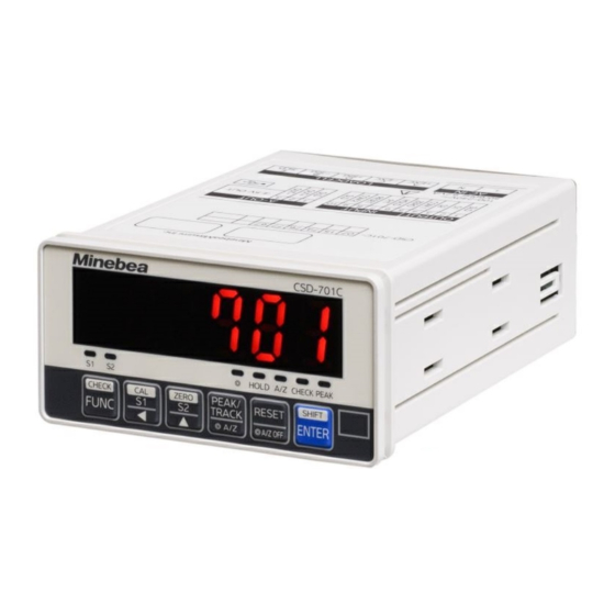
Page 13: Part Names And Functions
Assessment display Indicates the result of comparison with the comparator function. ② ③ Status display Indicates the CSD-701C status. Illuminates when the A/Z function is selected in function ◎ mode. Goes out when the peak hold function is selected in function mode. -
Page 14: Operation Panel
1.1.2 Operation Panel The main functions of the individual keys are described here. For more details of key operations, see “4.1 Operating Instructions”. Switches to function mode. ④ Calls up the comparator S1 setting. ⑤ Also moves the setting digit to the left when setting numerical values. -
Page 15: Rear (Rear Panel)
1.2 Rear (Rear Panel) ⑦ ① ⑥ ② ⑤ ④ ③ ① Analog output connector board Used to connect the analog output to external devices. ② USB interface connector Used to connect to a PC. (Type B mini USB connector) •... -
Page 16: Top And Sides
1.3 Top and Sides 1.3.1 Top Serial number Indicates the serial number of the equipment. ① ② Options Circles marked next numbers corresponding to options fitted to the equipment. The numbers correspond to the following options: 07: Current output [4 mA to 20 mA DC] 15: BCD output 74: RS-232C 76: RS-422/485... -
Page 17: Sides
1.3.2 Sides ① ① Bracket attachment slots Used for attaching the dedicated panel mounting brackets when the equipment is installed in a control panel. For details of the installation procedures, see “2.1 Installation”. -
Page 18: Installation
2. Installation 2.1 Installation 2.1.1 Control Panel Installation Procedure When mounting the equipment in a control panel, use the panel mounting brackets provided If the equipment is to be used in an environment where water droplets or dust may be present, insert the panel mounting seal provided between the equipment and the control panel (cabinet). -
Page 19: External Dimensions
2.1.2 External dimensions 2.1.3 Panel Cutting Dimensions... -
Page 20: Connections
3. Connections 3.1 Connector Board Connections 3.1.1 Connector Board Assignment The rear panel of the equipment includes the following connector boards. Power supply connector board (AC IN) █ Terminal Signal Description AC power supply AC power supply Load cell connector board (LOADCELL) █... -
Page 21: Connection Method
Analog output (A-OUT) █ Terminal Signal Description Shield OUT+ Analog output + OUT - Analog output - 3.1.2 Connection Method Wiring precautions █ The following points must be strictly observed regarding the connections CAUTION for this equipment. Failure to do so may result in unforeseen failure or damage. Always turn off the power before connecting wires. - Page 22 Compatible cables Single-core 0.2 to 1.5 mm Multi-core 0.2 to 1.5 mm Multi-core with ferrule (with plastic sleeve) 0.2 to 0.75 mm 24 to 16 Compatible ferrule AI 0,25 - 8 YE / AI 0,34 - 8 TQ Conductor length 8 mm connectors AI 0,5 - 8 WH/ AI 0,75 - 8 GY Phoenix Contact product or equivalent...
-
Page 23: Connecting Devices
This section describes how to connect a load cell. Other types of strain gauge based transducer can be connected in the same way. Connection between one load cell and the CSD-701C • If the total CAB-502 length is 30 m or greater, the input voltage to the equipment may drop... - Page 24 Connection between one load cell, an extension junction box (B-304), and the CSD-701C • If the total CAB-502 length is 30 m or greater, the input voltage to the equipment may drop due to the resistance of the cable, which may affect the guarantee regarding accuracy.
- Page 25 Connection between two to four load cells, a summing type junction box (B-307), and the CSD-701C • If the total CAB-502 length is 30 m or greater, the input voltage to the equipment may drop due to the resistance of the cable, which may affect the guarantee regarding accuracy.
- Page 26 Connection between two to four load cells, a summing typejunction box (SB-310), and the CSD-701C • If the total CAB-502 length is 30 m or greater, the input voltage to the equipment may drop due to the resistance of the cable, which may affect the guarantee regarding accuracy.
-
Page 27: Connecting External Control Input
3.2.2 Connecting External Control Input The external control input consists of “ZERO”, “HOLD”, “PEAK/TRACK”, and “RESET” control signals. These are enabled by connecting the individual terminals with COM.2 (terminal No. 9) or shorting them using an open collector, as shown in the following diagram. For information on the individual input functions, see “6.1 External Control Input Signals, Contact Output... -
Page 28: Connecting Contact Output
3.2.3 Connecting Contact Output To connect the contact outputs “S1” and “S2” to the external load, connect each to COM.1 (terminal No. 4) as shown in the following diagram. Take care to ensure that the load does not exceed the contact ratings. Contact rated load 125 V AC 0.1 A (resistance load) 30 V DC 0.5 A (resistance load) Connect the contact output correctly as shown in the diagram, and use within... -
Page 29: Connecting Analog Output
3.2.4 Connecting Analog Output Standard specifications (with voltage output) As standard, the equipment provides analog output in the form of voltage output. The voltage output connection is as shown in the following diagram. Voltage output -5.0 V to 5 V.0 DC “-OL”... - Page 30 Optional specifications (with current output) The current output connection is as shown in the following diagram. Current output 4.0 mA to 20.0 mA DC “-OL” indication Approx. 1.0 mA DC Overload “OL” indication Approx. 26.0 mA DC Load resistance Max. 260 Ω •...
-
Page 31: Power And Ground Connections
3.2.5 Power and Ground Connections Connect the power supply and ground as shown in the following diagram. Power supply voltage 100 V to 240 V AC (permissible variation range: 85 V to 264 V AC) Power supply frequency 50/60 Hz Power consumption Max. -
Page 32: Operation
4. Operation 4.1 Operating Instructions This section describes how to operate the equipment using the keys on the front panel. 4.1.1 Measurement Mode and Key Operation ■ Measurement mode This mode displays the current load and status when the equipment power is turned on. - Page 33 When Operated in Other Modes (1) Move setting digit to left Pressing the key while a setting is displayed moves to the left digit. (2) Function selection Selects a function in function mode or in check mode. (3) Fine adjustment decrement Pressing the key during ZERO, SPAN, or analog output fine adjustment decrements the corresponding value.
-
Page 34: Mode Selection
When Operated in Other Modes (1) Calibration Resets the setting if pressed while a setting is being entered during calibration. (2) Function mode Forcibly resets the number or setting to zero if pressed while a function number or function setting is being entered. (3)... -
Page 35: Mode Overview
Easy Calibration Mode █ Easy calibration mode is selected by pressing the (CAL/S1) key while pressing (SHIFT/ENTER) key. Easy calibration mode cannot be selected if it was locked using function F-13. (CAL/S1) key cycles through the modes as follows: → →... - Page 36 Consider an example in which a 100 kg weight is placed on top of a measuring device. If the equipment is not calibrated: Load and decimal point display position are not displayed correctly. After the equipment is calibrated: Correct load is displayed and the decimal point is placed in the correct position as set.
-
Page 37: Calibration Procedure
4.2.2 Calibration Procedure For details of the actual procedure, see “4.2.5 Calibration Procedure”. Check the connection between the load cell and the equipment, then connect the power supply. Allow to stand for approximately 10 minutes after connecting to let the equipment and load cell stabilize. - Page 38 • Recalibrate as needed if used in a different environment. • Recalibration is not required if already calibrated by Minebea in conjunction with a load cell. • If weights equivalent to at least two thirds of the maximum reading are available, calibrate using an actual load.
-
Page 39: Selecting Calibration Method
Zero calibration using numerical value input (electrical calibration) can be used only when the CSD-701C in use has been replaced by another CSD-701C, and all of the following conditions are satisfied: The zero calibration data (mV/V value) of the original CSD-701C is available. -
Page 40: Calibration Procedure
4.2.5 Calibration Procedure This section describes the procedure for calibration from the initially shipped state. In this example, the maximum reading is 6.000, and the minimum scale division is 0.002. • Units are not displayed on the display. If required, affix the units sticker provided in an appropriate place. - Page 41 Once set, press the key to display Press the key from the display to display * The currently stored minimum scale division is displayed. Stored minimum scale division Set the desired minimum scale division. Use the key or key to select the desired minimum scale division.
- Page 42 Set the desired maximum reading value. key: Selects the digit to be altered. key: Alters the value of the digit to be altered. Once set, press the key to display Press the key from the display to display * The currently stored weight mass is displayed. Weight mass for maximum reading Set the weight mass.
- Page 43 Maximum reading and weight mass setting error display This blinks for approximately two seconds if the maximum reading is smaller than the weight mass setting. * Set so that the maximum reading is greater than or equal to the weight mass. With only the initial load or tare applied to the measuring device, read off the load cell output, then store the zero point.
- Page 44 Set the load cell output corresponding to the load cell zero point in units of mV/V. key: Selects the digit to be altered. key: Alters the value of the digit to be altered. Once set, press the key to display Zero calibration error display This blinks for approximately two seconds if the load cell output or input value is outside the zero adjustment range on the negative side...
- Page 45 Enter the value corresponding to the load cell output expected when subjected to the maximum reading load minus the zero point load cell output, then store the span point. Refer to “4.2.3 Selecting Calibration Method” and select the span calibration method. Press the key to display , then press the...
-
Page 46: Zero Fine Adjustment
is displayed after span calibration is complete. Press to exit calibration mode. The equipment returns to measurement mode. Measurement Mode • The settings are temporarily stored until the key is pressed on the screen to confirm. The settings will not be saved if the procedure is canceled midway. •... -
Page 47: Span Fine Adjustment
• Holding down the following keys allows continuous decrementing/incrementing. • Each press of the following keys changes the load value by less than one digit. The following keys must sometimes therefore be pressed two or three times to change the reading by one digit. key: Decrements the value by one. -
Page 48: Calibration To Re-Register Zero Point Only
• Holding down the following keys allows continuous decrementing/incrementing. Each press of the following keys changes the load value by less than one digit. The following keys must sometimes therefore be pressed two or three times to change the reading by one digit. key: Decrements the value by one. -
Page 49: Calibration Locking
With no load placed on the measuring device, press the key. blinks on the load display, and zero calibration starts. Be careful here that load fluctuations are not applied, such as those due to vibration. Error code CAUTION If the load fluctuates, the zero point will not stabilize, preventing the correct zero from being read in. -
Page 50: Easy Calibration
4.3 Easy Calibration Pressing the key while pressing the key allows quick access to the corresponding setting screen and calibration screen. • The easy calibration function is initially locked when shipped. Therefore, you must unlock the function first. Refer to “4.6.1 Setting Procedure”... -
Page 51: Span Mode
Once the necessary items have been set, press when is displayed. blinks for two seconds, the setting is stored, and the equipment returns to measurement mode. Measurement Mode • The settings are temporarily stored until the key is pressed with displayed to confirm. -
Page 52: Zero Mode
4.3.3 ZERO Mode This is used to read in the load cell zero point output and perform zero calibration. Measurement Press the key and key together. Mode Press the key to cycle through → → and select , then press the key. -
Page 53: Check Mode
4.4 Check Mode The following items can be checked in check mode: Selecting EzCTS mode ROM version SUB ROM version Mounted options Bridge voltage External control input Contact output Analog output BCD output (option) ... - Page 54 Checking ROM version Press the key. The ROM version is displayed on the display. Pressing the key again causes the display to change to Checking SUB ROM version Press the key. The SUB ROM version is displayed on the display. Pressing the key again causes the display to change to Checking options...
- Page 55 Checking external control input Press the key. blinks, enabling the external control input signal on/off status to be monitored using the status indicator LEDs. LED indicator Corresponding input signal RESET input ◎ HOLD HOLD input ZERO input CHECK None PEAK PEAK/TRACK input Pressing the key again causes the display to change to...
-
Page 56: Ezcts Mode
The load is displayed on the display. 4.4.2 EzCTS Mode EzCTS is a PC application sold separately. It allows CSD-701C function data to be imported/exported and calibrated easily via a PC. It is useful for maintenance and data backup. USB cable... -
Page 57: Monitor Mode
4.5 Monitor Mode Monitor mode converts the load applied to a load cell to mV/V and displays the result. For example, if the output is unknown when using a load cell, this function should be used to read off the load cell output for initial load and maximum load, and these values should be used for calibration. -
Page 58: Function Mode
4.6 Function Mode The equipment stops measurement while function mode is selected. The outputs will therefore not change even when load cell input variations CAUTION occur, potentially damaging the equipment due to malfunctioning peripheral devices. • Function mode cannot be selected if a HOLD signal is input while HOLD is enabled (F-10) for the display. -
Page 59: Function Data
5. Function Data ●: Default setting Function Setting Reference Item Details value 6.8.2 Decimal point display F-01 ● 0 None position selection AD sampling frequency F-02 10 cycles setting 20 cycles 50 cycles ●100 100 cycles 6.8.1 Display frequency F-03 ●... - Page 60 Function Setting Reference Item Details value 4.3.4 Easy Calibration Locking F-13 Unlock ●1 Lock Stabilizing digital filter F-15 001 to Units: cycles number of moving-average 000: Stabilizing filter OFF samples ●016 * Available only when F-16 is set between 0.01 and 9.99 and when F-17 is set between 001 and 999.
- Page 61 Function Setting Reference Item Details value BCD flag output logic F-43 ● 0 Negative logic setting Positive logic BCD P.C. output logic F-44 ● 0 Negative logic setting Positive logic BCD P.C. width setting F-45 ●125 25 ms 10 ms 5 ms BCD output frequency F-46...
- Page 62 Function Setting Reference Item Details value 6.17 Zero and A/Z data storage F-71 00 to 11 0: RAM area location ●01 1: EEP area digit: ZERO data digit: A/Z data External input validity F-72 ● 50 50 ms period (pulse/level) 20 ms 10 ms 5 ms...
-
Page 63: Other Functions
6. Other Functions 6.1 External Control Input Signals, Contact Output Signals This equipment can be controlled externally using input signals. 6.1.1 External Control Input Signals These function by shorting with COM.2 (terminal No. 9). Terminal Name Type ZERO Shorts to trigger the zero setting function and forcibly reset the display to zero when the reading is less than 10 % of the maximum reading. -
Page 64: Equivalent Circuit
6.1.3 Equivalent Circuit (1) External control input (2) Contact output 6.1.4 Enable Recognition Time for Input Function F-72 can be used to set the time elapsed from input detection to signal recognition. Setting range: Selectable from 50, 20, 10, 5, 2 (Default setting: 50) Units: ms This setting also applies to the BCD input signal. -
Page 65: Comparator
6.3 Comparator The equipment incorporates a comparator, which uses the S1 and S2 settings. • The equipment comparator compares synchronized with the sampling frequency. 6.3.1 Comparator On/Off The operation of the S1 and S2 comparators for the equipment can be individually enabled and disabled. -
Page 66: Comparator S1 And S2 Operation
6.3.3 Comparator S1 and S2 Operation The S1 and S2 comparators for the equipment can be individually set to turn on the contact for a value either above or below the setting. The default for both S1 and S2 is for the contact to be turned on for a value above the setting. -
Page 67: Comparator S1 And S2 Comparison Target
6.3.4 Comparator S1 and S2 Comparison Target The operation of the S1 and S2 comparators for the equipment can be individually selected to compare “TRACK/Total load” or “PEAK/Reading”. The default for both S1 and S2 is “TRACK/Total load”. These can be set using function F-31. Setting range: 00000 to 11111 (Default setting: 00000) 0: TRACK/Total load 1: PEAK/Reading... - Page 68 Setting range: 0 to 1 (Default setting: 1) 0: On delay 1: Off delay Hysteresis data width can be set using function F-35. Setting range: 00 to 99 (Default setting: 0) Units: digits Hysteresis duration can be set using function F-36. ...
-
Page 69: Using Filters
(3) With “Contact on below the setting” selected and hysteresis effective direction set to [On delay] (4) With “Contact on below the setting” selected and hysteresis effective direction set to [Off delay] 6.4 Using Filters The equipment incorporates digital filters that apply arithmetic processing to stabilize digitally converted data. -
Page 70: Digital Filter
• Values exceeding the range of settings will automatically be constrained to a value within the valid range. • If the low-pass filter setting falls outside the above range after the AD sampling frequency is changed, the low-pass filter setting will be forcibly changed to a value corresponding to 1/10 of the sampling frequency. -
Page 71: Stabilization Filter
• Do not use zero tracking in cases in which the load fluctuates slowly around the zero point. • If, despite significant changes, the load reading fluctuates slowly due to the strength of the digital filter and/or stabilization filter, zero tracking may be enabled. Take care regarding this. Canceling correction due to zero tracking █... -
Page 72: Stabilization Filter Settings
6.6.3 Stabilization Filter Settings Function F-17 can be used to set the data width for applying stabilization filtering. Setting range: 000 to 999 (Default setting: 20) Units: digits The stabilization filter width for the setting “n” set using function F-17 is given by the following equation using display values: [Stabilization filter data width] = [F-17 setting] ×... -
Page 73: Peak Function And A/Z Function Selection
6.7 Peak Function and A/Z Function Selection Function F-70 is used to set the function (“Peak function” or “A/Z function”) operating when key is pressed. Setting range: 0 to 1 (Default setting: 0) 0: Peak function enabled 1: A/Z function enabled 6.8 Display Related Functions 6.8.1 Display Frequency Selection Function F-03 is used to set the display frequency for the equipment. -
Page 74: Using Peak Hold
6.9 Using Peak Hold The equipment incorporates a peak hold function. The function retains the maximum load value. • When the PEAK/TRACK input is shorted, the peak hold status will not change even when the key is turned on. 6.10 Hold Target Selection Function F-10 can be used to set combinations of “Load display”, “Comparator S1/S2 contact output, LED display”, “Analog output”, and “Option output”... -
Page 75: Bridge Power Supply Voltage Selection
6.11 Bridge Power Supply Voltage Selection Function F-12 can be used to select the bridge power supply voltage. Setting range: Selectable from 5 or 2.5 (Default setting: 5) Units: V • Recalibration must be performed after changing the bridge power supply voltage. 6.12 Auto Zero (A/Z) The equipment incorporates an auto zero (A/Z) function, which can be used to automatically zero load measurements. -
Page 76: Check Value
digit: S1, S2 digit: ZERO key digit: FUNC. key The following corresponding functions will be limited: CHECK key: CHECK value ON/OFF (Press key while pressing key) Peak hold function ON/OFF, A/Z ON ( key), peak reset, A/Z OFF ( key) ... -
Page 77: Analog Output Scaling
6.16.2 Analog Output Scaling The analog output minimum and maximum values for the standard specifications are set to 0 and 30,000, respectively. Use F-21 and F-22 to modify the minimum and maximum values. Use function F-21 to set the reading when the minimum value is output. Setting range: -99999 to 99999 (Default setting: 0) Use function F-22 to set the reading when the maximum value is output. - Page 78 (2) Voltage output When minimum reading F-21 = -10,000 and maximum reading F-22 = 10,000 (3) Current output When minimum reading F-21 = 0 and maximum reading F-22 = 10,000...
-
Page 79: Analog Fine Adjustment 1
(4) Current output When minimum reading F-21 = 10,000 and maximum reading F-22 = 10,000 6.16.3 Analog Fine Adjustment 1 The fine adjustment described here involves adjusting the respective maximum and minimum values without applying an actual load. For details of the fine adjustment with an actual load applied, see “6.16.4 Analog Fine Adjustment 2”. -
Page 80: Analog Fine Adjustment 2
Press the key. The display changes to blinking. The analog output corresponding to the minimum analog output value is output here. Use the following keys to adjust to achieve the minimum output. Standard specifications Optional specifications (voltage output) (current output) 0.0 V 4.0 mA •... - Page 81 • To abort fine adjustment midway, press the key. The zero data and span data prior to fine adjustment is retained, and the equipment returns to measurement mode. • Wait at least one hour after turning on power before performing fine adjustment. This ensures that fine adjustment is performed in more stable conditions.
-
Page 82: Analog Output Target Selection
key: Decrease analog output key: Increase analog output Press the key. The display changes to Pressing the key again exits VADJ mode and returns to measurement mode. The current load is displayed. The fine adjustment results for the maximum and minimum analog output values are updated here. -
Page 83: Optional Functions
7. Optional Functions The following options are available for the equipment: Options ① to ⑤ are subject to certain combination restrictions, as shown in the following table: 〇: Available, ×: Not available – 〇 〇 〇 〇 ○ – × ×... -
Page 84: Current Output
7.1 Current Output • For details of the wiring procedures see “3.1.2 Connection Method”. 7.1.1 Related Functions F-20 Analog output target setting TRACK/Total load, PEAK/Reading F-21 Reading for minimum analog output Reading for approx. 4 mA output F-22 Reading for maximum analog output Reading for approx. -
Page 85: Bcd Output Specifications
7.2.2 BCD Output Specifications Specifications Details Output logic Negative or positive logic can be selected using related functions F-41, F- 42, and F-43. Output data BCD: Five-digit parallel output POL. (polarity): Output on for negative polarity and off for positive polarity P.C. -
Page 86: Input Output Equivalent Circuit
• The engagement locking screws for the BCD output connector plugs are imperial screws. 7.2.4 Input Output Equivalent Circuit (1) Input equivalent circuit (2) Output equivalent circuit 7.2.5 Timing Chart To avoid errors, read in BCD output data via a sequencer or other device timed to coincide with the on-to-off change edge of the P.C. - Page 87 (1) Normal • The output transistor turns on when data is output for P.C., DATA, and POL. (negative electrical logic). When data over occurs • The OVR signal output transistor turns on when OVR is output (negative electrical logic). • All output transistors turn off for DATA when OVR is output (positive electrical logic). (However, POL.
-
Page 88: Output Status
(3) When a HOLD signal is input 7.2.6 Output Status BCD output logic is set using function settings. (Related functions: F-41, F-42, F-43, F-44) The BCD output status will be as shown in the following table: Pin-COM level with Output logic Output data Transistor status external voltage... -
Page 89: Rs-232C Interface
External control input █ ZERO, HOLD, PEAK/TRACK, and RESET external control input signals can be input via the BCD connector. For details of the signals, see “6.1 External Control Input Signals, Contact Output Signals”. 7.3 RS-232C Interface • In modes other than measurement mode (e.g., function mode, calibration mode, fine adjustment mode, setting mode), an error command will be sent in response to commands from the host. -
Page 90: Connector Pin Layout And Connections
(2) Command mode Predetermined commands or data from the host (e.g., PC or sequencer) are sent to the CSD-701C; data is returned to the host by the CSD-701C in response to those commands or data. Always use the following steps for communications. - Page 91 Requires a flathead screwdriver. Strip the cable sheath. Insert the wire via the wire opening. Tighten the screw on the top of the connector using the screwdriver. Mount the connector on the equipment. RS-232C interface wiring examples Example 1 CSD-701C Host (25-pin)
-
Page 92: Data Format
Example 2 7.3.5 Data Format (1) Stream mode The terminator contains the data set by F-55. The load data is right-aligned. The sign is “-” when negative and “+” when positive. The load data is subject to zero suppression. ... - Page 93 (2) Command mode Load data reading (Host → CSD-701C) Command number Type TRACK/Total load reading PEAK/Reading reading A/Z reading Terminator Command number Return (CSD-701C → Host) Terminator Load data sign Load data Command number The load data is right-aligned. ...
- Page 94 ◎ Comparison results reading return Terminator S4 (fixed at 0) Command S3 (fixed at 0) S0 (fixed at 0) Comparison data reading (Host → CSD-701C) Command number Type S1 data reading S2 data reading Terminator Command number Return (CSD-701C → Host)
- Page 95 Zero control Command number Type Status update: Zero set Status update: A/Z ON Status update: A/Z OFF The same command number is returned when executed successfully. Comparison data writing (Host → CSD-701C) Command number Type S1 data reading S2 data reading...
- Page 96 Terminator Sign Setting value Command number Return (CSD-701C → Host) Terminator Sign Setting value Command number Set the setting value right-aligned. The setting range is -99,999 to 99,999. Do not add decimal point. Function setting Command number...
-
Page 97: Communication Function Data
7.3.6 Communication Function Data ●: Default setting Function Setting Reference Item Details value 6.8.2 Decimal Point Display F-01 ● 0 None Position Selection AD Sampling Frequency F-02 10 cycles Setting 20 cycles 50 cycles ●3 100 cycles 6.8.1 Display frequency F-03 ●... - Page 98 Function Setting Reference Item Details value Stabilization filter F-15 1 to 512 Sets same frequency Digital filter number of ●16 moving-average samples Stabilization filter F-16 0 to 999 Unit: 0.01 s time width setting ●20 Stabilization filter data F-17 0 to 999 Units: digits width setting ●20...
- Page 99 Function Setting Reference Item Details value BCD P.C. width setting F-45 ● 0 25 ms 10 ms 5 ms BCD output frequency F-46 ● 0 4 cycles/s setting 20 cycles/s 50 cycles/s 100 cycles/s RS-232C/422/485 F-49 Stream mode Operating mode setting ●1 Command mode RS-232C/422/485...
-
Page 100: Calibration Command
Function Setting Reference Item Details value External input validity F-72 ● 0 50 ms period 20 ms 10 ms 5 ms 2 ms Serial I/F operating mode F-88 ● 0 Stream selection Stream + auto printing Stream + manual printing 4.2.4 Calibration data, F-90... - Page 101 Mode selection command Return Calibration assessment Calibration status reading command Return Registration in progress Registration complete Terminator Command...
- Page 102 Minimum scale registration Minimum scale setting command The same command number and setting are returned when the setting has been successfully executed. Maximum reading registration Maximum reading setting command Terminator Command Maximum reading The same command number and setting are returned when the setting has been successfully executed.
- Page 103 Return Zero mV/V value registration Zero mV/V command The same command number and setting are returned when the setting has been successfully executed. Span mV/V value registration Span mV/V command The same command number and setting are returned when the setting has been successfully executed.
- Page 104 Zero fine adjustment registration Zero fine adjustment command The same command number and setting are returned when the setting has been successfully executed. Span fine adjustment registration Span fine adjustment command Terminator Command Span fine adjustment registration The same command number and setting are returned when the setting has been successfully executed.
-
Page 105: Communication Error Processing
Decimal point display position setting Decimal point display position setting command The same command number and setting are returned when the setting has been successfully executed. Calibration prohibition Calibration prohibition command The same command number is returned when executed successfully. 7.3.8 Communication Error Processing If communication errors or execution errors occur, the equipment returns an error command to the host. -
Page 106: Rs-422/485 Interface
7.4 RS-422/485 Interface • In modes other than measurement mode (e.g., function mode, calibration mode, fine adjustment mode, setting mode), an error command will be sent in response to commands from the host. • Note the following points when using the CHECK switch: Enabling CHECK exits measurement mode, but the RS-422/485 ①... -
Page 107: Data Transfer Procedure
Predetermined commands or data from the host (e.g. PC or sequencer) are sent to the CSD- 701C, and data is returned to the host by the CSD-701C in response to those commands or data. Always use the following steps for communications. - Page 108 The wiring procedure for the connector plugs provided is the same as for the RS-232C interface. For details, see “7.3.4 Connector Pin Layout and Connections”. Wiring examples 1 to 1 RS-422 host CSD-701C TRM. S.G. S.G. RS-485 host CSD-701C TRM.
-
Page 109: Data Format
1 to n RS-422 host CSD-701C RS-485 host CSD-701C Address 00 Address 00 TRM. TRM. S.G. S.G. S.G. S.G. CSD-701C CSD-701C Address 01 Address 01 TRM. TRM. S.G. S.G. CSD-701C CSD-701C Connect Connect Address 09 Address 31 terminal terminal resistance at resistance at TRM. -
Page 110: Serial Interface
7.5 Serial Interface Note the following points when using the CHECK switch: ① Enabling CHECK exits measurement mode, but the serial interface will maintain output even in this case. CAUTION Enabling CHECK may result in an “OL” error to appear. ②... -
Page 111: Connection Method And Internal Equivalent Circuit
7.5.4 Connection Method and Internal Equivalent Circuit • Devices compatible with a serial interface include Unipulse printers and display units. • Use 2-core shielded cables for all cables where possible. If shielded cables are not used, twist the cables together. (Cables should not be more than 100 m long for shielded cables and not more than 20 m long for twisted cables.) •... -
Page 112: Format And Data Description
SET when display is NET SET when display is GROSS GROSS data/NET data G1/ N1 G2/ N2 G3/ N3 Decimal DP 10 point Load data / BCD data None Sign (SET when negative) Decimal point • Serial data is output only in measurement mode. 7.5.6 Format and Data Description Auto print bit [FUN1: bit 0] ... -
Page 113: Dc Power Supply Voltage
7.6 24 V DC Power Supply Voltage 7.6.1 Terminal Board Assignment The following table shows the power supply terminal board assignment for a 24 V DC power supply voltage. 7.6.2 Power Supply Voltage (DC-IN) Terminal Signal Description DC power + DC power - •... -
Page 114: Troubleshooting
A/D conversion error: ER-3 Occurs when internal A/D conversion is If the problem persists even after turning not functioning correctly. the power off and then back on again, there may be a fault. Contact Minebea. Calibration error: ER-4 Occurs when... -
Page 115: Troubleshooting
If the problem persists even after turning EEPROM error: ER-W EEPROM. the power off and then back on again, there may be a fault. Contact Minebea. Occurs when data cannot be read from If the problem persists even after turning EEPROM error: ER- R EEPROM. - Page 116 Phenomenon Check point Check whether the pulse input is a signal at least 50 ms long (F-72 setting). Check whether the level input is a continuous signal at least 50 ms long (F-72 setting). Check whether the signal cable is correctly connected. The contact output can be checked in check mode.
- Page 117 RS-422/485 Interface █ Phenomenon Check point Check whether the RS-422/485 cable is correctly connected. Check whether the required terminal resistance has been connected (shorting between TRM. and RDB). Check whether RS-422 and RS-485 switching is correctly set. Check whether the address number (F-57) is correctly set. Communications are not Check whether the communication interface settings (F-49, F-51 to F- established.
-
Page 118: Appendix
9. Appendix 9.1 Character Display Patterns The equipment displays characters as follows on the 7-segment display:... -
Page 119: Function Setting Table
9.2 Function Setting Table Refer to this if you have altered function settings. Function No. Default Customer Function No. Default Customer setting setting F-51 9600 F-01 F-52 F-02 F-53 F-03 F-54 F-04 00000 F-55 F-06 F-56 F-07 00.0 F-57 F-08 F-58 F-09 1111...
Need help?
Do you have a question about the CSD-701C and is the answer not in the manual?
Questions and answers