Table of Contents
Advertisement
Quick Links
WEIGHT CONVERSION MODULE
CSD-892B-07-25
Instruction Manual
General
Installation/Wiring
Changeover of mode
Calibration
Setting of Function
Setting of Comparator
Check mode
Analog output
USB (RS-232C)
interface
Trouble shooting
Specifications & others
EN294-1966A
Advertisement
Chapters
Table of Contents

Related Manuals for Minebea CSD-892B-07-25


Summary of Contents for Minebea CSD-892B-07-25
- Page 1 General WEIGHT CONVERSION MODULE Installation/Wiring CSD-892B-07-25 Changeover of mode Instruction Manual Calibration Setting of Function Setting of Comparator Check mode Analog output USB (RS-232C) interface Trouble shooting Specifications & others EN294-1966A...
- Page 3 Thank you very much for your purchasing our Weight Conversion modeule, model CSD- 892B-07-25. This manual for CSD-892B-07-25 explains the procedures and check points in operation. We would like you to read through this instruction manual with much care for the best use of our product to avoid malfunctions.
- Page 4 For safe operation Be sure to read this manual before use. Ⅰ. Location of installation Caution • Use the Instrument under the following conditions. Environmental temperature:-10 ℃ ~ 50 ℃(Preservation:-20 ℃ ~ 60 ℃) ● Environmental humidity:85 %RH or less. (Non-condensing) ●...
- Page 5 Ⅱ. Installing the instrument When you set up two or more devices, you can install on the same panel with no clearance in between. Caution • Please secure and set up the space between this instrument and the device ■ Outline dimensions Front Side 67.4...
- Page 6 ON, operator may have an electric shock or the instrument may be destroyed. • Before supplying power, check the indication of power voltage/specifications to be identical with supplied power. If they are not identical, contact with Minebea. Without checking the above, operation may cause damage to the instrument or electric shock.
- Page 7 Ⅴ. Conformity standard This instrument has suited the following standard. EN61326-1:2013 "Electrical equipment for measurement, control, and laboratory use - EMC requirements" "Immunity test requirements for equipment intended for use in industrial locations" JIS B 7611-2:2015 "Non-automatic weighing instruments - Metrological and technical requirements and test - Part2: Measuring instruments used in transaction or certification."...
- Page 8 [Net weight offset function] hall be applied the value of 00000. Ⅵ. Function set when this is used in the tank weighing system • When using CSD-892B-07-25 as a tank weighing system, the setting of the function shall be changed to as below.
- Page 9 Revision history Date Instruction No. Reason of revised (Contents) 2022/04 DRW. NO. EN294-1966 First version ROM Ver.3.000 ECN No.FN22-0210 -Correction- V.Conformity standard <Before the change> RoHS directive <After the change> RoHS compliant 2-4.Connecting of power supply and ground [Point!] 2022/05 DRW. NO. EN294-1966A 2-5.Connection with external control I/O <Before the change>...
- Page 10 CONTENTS FOREWORD …………………………………………………………… I For safe operation …………………………………………………… II Location of installation ……………………………………………………………… II Ⅰ. Installing the instrument ……………………………………………………………… III Ⅱ. Power supply ………………………………………………………………………… IV Ⅲ. Instruction for usage ………………………………………………………………… IV Ⅳ. Conformity standard ………………………………………………………………… V Ⅴ. Function set when this is used in the tank weighing system …………………………………………… VI Ⅵ.
- Page 11 5. C function mode …………………………………………………… 44 5-1. Setting method of C function mode ………………………………………………… 44 5-2. Details of C function data …………………………………………………………… 45 6. Various operations by C function data ………………………… 47 6-1. Decimal point display position ……………………………………………………… 47 6-2. A/D sampling ………………………………………………………………………… 47 6-3.
- Page 12 9-2. Details of S function data …………………………………………………………… 69 10. Various operations by S function data …………………………… 71 10-1. Measurement mode ………………………………………………………………… 71 10-2. Control mode ………………………………………………………………………… 71 10-3. Operation of comparative signal …………………………………………………… 71 10-4. Comparative operation at NEAR ZERO (ZERO BAND) ………………………… 71 10-5.
- Page 13 14-2. Specifications of the voltage output ………………………………………………… 105 14-3. Scaling of analog output …………………………………………………………… 105 15. USB(RS-232C) interface ………………………………………… 108 15-1. Specifications of interface …………………………………………………………… 108 15-2. Operation mode ……………………………………………………………………… 108 15-3. Command data format ……………………………………………………………… 110 15-4. Data format for stream mode ……………………………………………………… 124 15-5.
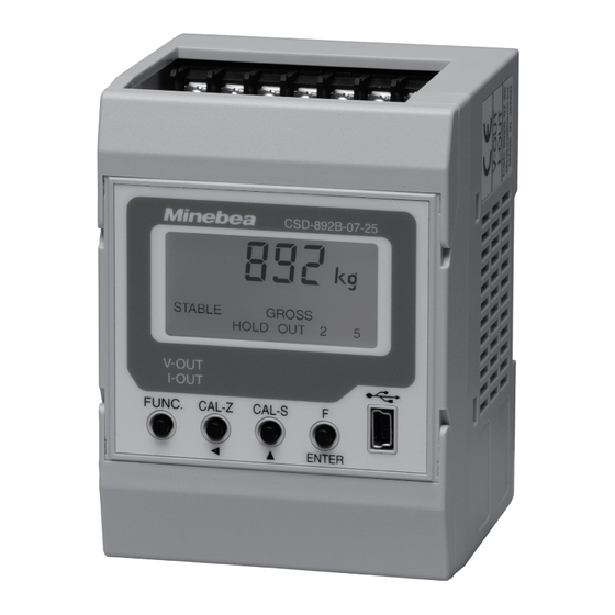
- Page 15 ② Load display section Display the Gross/Net, Overload or Error. In the various setting mode, display the condition and the setting value. ③ Condition display section Display the condition of CSD-892B-07-25. ZERO Light on when the zero calibration is processed. SPAN Light on when the span calibration is processed.
- Page 16 The subject driver installation is needed. Please download from Minebea's homepage, and install it to the PC. Additionally, EzCTS_USB1 (Optional software for PC) is convenient for reading, writing, saving and printing the setting data by connecting with PC.
- Page 17 1-2. Upper and lower part of front panel CSD-892B-07-25 ④ Connector for analog output ② Terminals for power supply and external control I/O (Lower part terminals) ① Cover-1 and -2 of terminal block ③ Terminals for load cell (Upper part terminals) ①...
- Page 18 2. Installation and Wiring 2-1. Attaching to and Removing from a DIN rail This instrument adopts the rail mounting type with 35 mm width of DIN standard. The procedures of attaching and removing are as follows: Attaching method to a DIN rail ①...
- Page 19 Load cell input - (Blue) Shield (Yellow) • When the length of CAB-501 (Minebea's standard cable) is more than 100 m totally, the accuracy may be out of warranty as the remote sensing function of the instrument does not work enough due to the resistance of the cable.
- Page 20 CSD-892B-07-25 does not work in normal operation when the terminal F and G is in the open status. • When the length of CAB-502 (Minebea's standard cable) is more than 30 m totally, Point! there may have the case that the accuracy is out of warranty due to the resistance of cable, the input voltage of the instrument will be decreased.
- Page 21 Load cell input - (Blue) +EXC Shield (Yellow) +SIG -SIG No.2 -EXC +EXC +SIG -SIG No.3 -EXC +EXC +SIG -SIG No.4 -EXC • CSD-892B-07-25 can make up to 4 parallel connections when the load cell is 350 Ω type. Point!
- Page 22 ④ Connecting the load cell and junction box B-304B for extension with CSD-892B-07-25 (1) When you use CAB-501 (6-cores cable) Junction box Load cell B-304B Load cell power supply + (Red) Sensing input + (Orange) Sensing input - (Black) CAB-501...
- Page 23 C-G of the load cell terminal board. When terminal F and terminal G are used with opening status, CSD-892B-07-25 cannot make normal operation. • When the length of CAB-502 (Minebea's standard cable) is more than 30 m totally, Point! the accuracy may be out of warranty due to the resistance of cable, the input voltage of the instrument will be decreased.
- Page 24 2-4. Connecting of power supply and ground Please connect the power supply and ground to the lower terminal block as shown in the following figure. ❶ F.G. Frame ground ❷ + 24 V Power supply DC24V 1 2 3 ❸ 0 V Power supply DC 0V D-class with single earth...
- Page 25 2-5. Connection with external control I/O You can control the function from the external control I/O terminals (Lower terminal block). The external control input is executed by shortening each input and COM1 with a contact point or open collector after wiring the connector. The external control output is an open electron collector output.(Open collector ratings V = DC35 V, I = DC50 mA MAX)...
- Page 26 For the connection of an analog output cable, use a shielded cable line and connect the ● shied with SLD terminal in the connector. When you connect the cable with CSD-892B-07-25, please check the direction of upper/ ● lower sides of the connector, and insert until it bumps.
- Page 27 2-7. Connection of surge absober If this instrument is compliant with the conforming JIS standard or EMC directive, connect the surge absorber as shown in the figure below. ❶ F.G. Frame ground ❷ + 24 V Power supply DC24V 1 2 3 ❸...
- Page 28 3. Operation 3-1. Changeover of mode CSD-892B-07-25 has various modes according to the operating situation. Please push the [F/ENTER] key when you display the mode that shifts with the [CAL-Z/ key and the [CAL-S/ ▲ ] key after pushing the [FUNC] key.
- Page 29 ① Function mode The setting concerning the following functions and (FUNC) effective/invalid are changed. • Various filter • Key lock • Detection of stability • Net amount offset function • Hold • Set of action for five steps comparator •...
- Page 30 3-2. Display transition diagram Measurement mode movement by pushing key. ▶ ENTER ENTER ▶ CAL-Z CAL-Z movement by pushing key. FUNC. FUNC. movement by pushing key. ▶ * * ▶ Function mode (F -**) (FUNC) * * ▶ C-function mode (CF-**)...
- Page 31 4. Calibration mode 4-1. What is calibration? The calibration is an operation that matches the load of the sensor to the display of this instrument to display the electrical signal from the sensor (load cell) as an accurate load. If the calibration is not processed, a correct display and an output cannot be taken. The example when the load cell is used is shown as follows.
-
Page 32: Table Of Contents
4-2. Procedure of calibration Please refer to [4-6. Details of calibration procedure] for the actual steps. After turning on DC24V, CSD-892B-07-25 is Advance preparation energized for about 10 minutes to stabilize Turn on power supply CSD-892B-07-25 and weighing section (load cell). -
Page 33: Step
• The environment used must execute the calibration again if necessary in altered case. • When Minebea has executed the calibration in the combination with load cell, you don't need to execute the calibration again. • Execute the calibration with actual load when you can prepare the weight of 2/3 or Point! more of weighing capacity. - Page 34 892B-07-25 under using is replaced with another CSD-892B-07-25, and moreover, only when the following requirement is applied. ・When ZERO calibration data (mV/V value) of CSD-892B-07-25 at the previous condition of the replacement remain. ・When you cannot set in the condition that nothing is put on the measuring part (Initial condition including tare).
-
Page 35: Switch To The Calibration Mode
4-6. Details of calibration procedure We explain the calibration procedures from a condition of factory shipment. For example, we explain by the case that the maximum display value is 6.000 t, and the scale interval is 0.002 t. Step Switch to the calibration mode Measurement mode 1... -
Page 36: Step
Step Set of decimal point display position 1 When key is pushed at ENTER is displayed. * The position of decimal point memorized now is displayed. The position memorized Select the position of decimal point. CAL-Z CAL-Z CAL-S CAL-S Select the position by key. -
Page 37: Step
Step Set the weighing capacity When key is pushed at display, ENTER is displayed. * The weighing capacity memorized now is displayed. The weighing capacity memorized now. Set the weighing capacity. CAL-Z CAL-Z Select the changed digit. Set-up weighing capacity CAL-S CAL-S Increment the value of selected digit. - Page 38 ZERO is registered by reading the load cell output value in the Step (Actual weight calibration) condition that nothing is put on the measuring part (Initial condi- ZERO Calibration by measurement value tion including tare). Please select the method of ZERO calibration referring to [4-3. Selection of Calibration Method] 1...
- Page 39 Step (Actual weight calibration) SPAN is registered by reading the output value in the condition to SPAN calibration by the weight put the weight set according to step 6. Please select the method of SPAN calibration referring to [4-3. Selection of Calibration Method] 1...
- Page 40 Step End of calibration 1 displays after the span calibration is finished. Push key to complete the calibration mode. ENTER The display becomes , and the set data is memorized internally. FUNC. FUNC. Measurement mode By pushing key twice, return to the measurement mode. •...
- Page 41 4-7. Fine adjustment of ZERO and SPAN This function fine-adjusts ZERO and SPAN when there is any difference margin in an actual weighing capacity and the mass of weight. You can register only of either the ZERO or SPAN. We explain the procedures for fine adjustment of SPAN after the fine adjustment of ZERO as follows.
- Page 42 Step to fine adjustment of SPAN 1 By pushing key from ENTER ENTER blinks. * The present measurement value is displayed. Please put the weight that can be put on the measuring part below weighing capacity, and adjust the display to become the value equal to mass of weight.
- Page 43 4-8. Fine adjustment of analog output This function is to adjust the analog output. It is also possible to register only either zero point or the span point. Set the output of zero point and span point previously referring to [6-14. Analog output setting item].
- Page 44 Step Fine adjustment of the output at span point 1 By pushing key from the display of display, ENTER flashes. * The voltage that equivalent to span point is output. Please adjust it while monitoring the voltage output. CAL-Z CAL-Z When you keep pushing Measurement value decreases.
- Page 45 4-8-2. Fine adjustment procedure of voltage output Step This function to adjust the analog output while actually Switch to fine adjustment mode of voltage output apply the load Measurement mode 1 Change from the standard measurement mode to the FUNC. FUNC.
- Page 46 Step Fine adjustment of the output at span point 1 By pushing key from the display of display, ENTER load the present value of the flashing. * The voltage that equivalent to span point is output. Please adjust it while monitoring the voltage output Load display CAL-Z CAL-Z...
- Page 47 4-8-3. Fine adjustment procedure of current output Step This function is to adjust the analog output without actually Switch to fine adjustment mode of current output applying the load. Measurement mode 1 Change from the standard measurement mode to the FUNC.
- Page 48 Step Fine adjustment of the output at span point 1 By pushing key from the display of display, ENTER flashes * The current that equivalent to span point is output. Please adjust it while monitoring the current output CAL-Z CAL-Z Measurement value decreases.
- Page 49 4-8-4. Fine adjustment procedure of current output Step This function to adjust the analog output while actually Switch to fine adjustment mode of current output apply the load.. Measurement mode 1 Change from the standard measurement mode to the FUNC. FUNC.
- Page 50 Step Fine adjustment of the output at span point 1 By pushing key from the display of display, ENTER load the present value of the flashing. * The current that equivalent to span point is output. Please adjust it while monitoring the current output. Load display CAL-Z CAL-Z...
- Page 51 4-9. Digital linearization After the calibration, the measurement error of some scale interval levels might be caused between ZERO and SPAN (maximum capacity) by the influence of the measuring section etc. The digital linearization function executes the compensation of three points or less except ZERO and SPAN, and to reduce the measurement error.
- Page 52 Step Setting of digital linearization 1 By pushing key twice from display, ENTER ENTER → Display changes in order of → As the display becomes by pushing → CAL-S CAL-S key from display, please select the numbers of points which wants to compensate linearization, and push key.
- Page 53 4-10. Calibration only of ZERO This function is for calibrating again only of the ZERO when the amount of the tare other than the maximum capacity of the measuring part are changed. Step Change to calibration mode only for ZERO Measurement mode 1...
- Page 54 4-11. Simple calibration Each item can be immediately shifted to a set screen and the calibration screen by pushing CAL-S CAL-S CAL-S FUNC. FUNC. FUNC. CAL-Z CAL-Z CAL-Z key for about 2 second or more. • Please use the simple calibration function after releasing the lock referring to [4-11-1. Simple calibration lock] because that function is locked at the shipment from factory.
- Page 55 4-11-2. Setting mode By pushing key for 2 seconds or more, you can set the unit, decimal point display position, scale interval, weighing capacity, ZERO calibration, SPAN calibration (both are calibration by numeric input). When the display blinks while setting the item and the item is fixed with the [F/ENTER] key, the display becomes a lighting display.
- Page 56 4-11-3. ZERO mode ZERO calibration is executed by reading the load cell output value at ZERO by pushing CAL-Z CAL-Z CAL-Z key for 2 seconds or more. Measurement mode CAL-Z CAL-Z CAL-Z CAL-Z Push for 2 By pushing key for 2 seconds or more from the normal seconds or more measurement mode, blinks.
- Page 57 4-11-4. SPAN mode The setting of weighing capacity and mass of weight, and span calibration by reading the CAL-Z CAL-Z CAL-Z load cell output value is executed by pushing key for 2 seconds or more. Measurement mode CAL-S CAL-S CAL-S CAL-S Push for 2 By pushing...
- Page 58 5. C function mode By setting of C function, the setting of the function related to the calibration, and changeover of valid / invalid is executed. 5-1. Setting method of C function mode Measurement mode 1 FUNC. FUNC. By pushing key from the normal measurement mode, displays.
- Page 59 5-2. Details of C function data Reference No. Item Function No. Set value Contents ● 0 No decimal point 1234.5 Display position of CF-01 123.45 decimal point 12.345 1.2345 50 times/s 100 times/s A/D sampling rate CF-02 250 times/s ● 3 500 times/s At exceeding | Weighing capacity + 9D | Condition of overload...
- Page 60 Reference No. Item Function No. Set value Contents ● 0 Invalid Stability detection in the 6-12 CF-20 setting. Valid ● 0 Set the district number Method of setting 6-13-1 gravity acceleration CF-25 Set the numerical value of gravity acceleration compensation CF-26 01~16 Unit : District...
- Page 61 6. Various operations by C function data 6-1. Decimal point display position The decimal point display position is selected by C function CF-01. Setting range : 0 ~ 4 0:Nothing 1:1234.5 2:123.45 3:12.345 4:1.2345 6-2. A/D sampling The A/D sampling rate is selected by C function CF-02 Setting range:0 ~...
- Page 62 6-6. Function to reverse the sign of net amount For instance, the net amount display and net amount data output outside in the simple comparative discharge mode display the negative value. The function to reverse the sign of net amount changes the net amount display and the net amount data output outside to a positive value by reversing the polarity of the net amount by C function CF-08.
- Page 63 6-8-2. Data width of ZERO tracking The data width of ZERO tracking is set by C function CF-13. Setting range : 000 ~ 999 :000 Unit : 0.1 DOFF:000 6-8-3. Time width of ZERO tracking The time width of ZERO tracking is set by C function CF-14. Setting range : 00 ~...
- Page 64 6-9. Power on ZERO The power on ZERO function makes the display to a zero if the change of display is within ±10 % of the maximum capacity when the power is turn on, or in the stable condition in the operation of display turning on.
- Page 65 6-11. Change of data stored place The data stored place of [Internal RAM] or [EEPROM] is selected by C function CF-17. Setting range:000 ~ 111 :100 0:Internal RAM 1:EEPROM * Each digit of the set value corresponds to the following items, and selects stored place of each digit.
- Page 66 6-13-2. Setting of district number of the using place (CF-25:0) The district number of the using place is set by C function CF-26. Please refer to the below list. Setting range:01 ~ 16 :No.10 district 6-13-3. Setting of district number of calibration place (CF-25:0) The district number of calibration place is set by C function CF-27.
- Page 67 6-14. Set item of analog output Execute the setting relative to the analog output 6-14-1. Output target of the voltage Set the output target of the voltage by C function CF-70. Setting range : 0,1,2 0:Load display 1:Gross value 2:Net value 6-14-2.
- Page 68 6-15. Calibration data (For reference) Scale interval, Weighing capacity, Mass of weight, ZERO mV/V value and SPAN mV/V value set at present is referred by C function CF-90 ~ CF94. 6-16. Stability detection time width in calibration Stability detection time width in calibration is set by C-function CF-97 Setting range : 00 ~...
- Page 69 7. Function mode Various functions become effective by setting the function data. 7-1. Setting method of function mode Measurement mode 1 FUNC. FUNC. By pushing key from normal measurement mode, the display becomes and you can enter into the function mode. By pushing key, displays.
- Page 70 7-2. Details of function data Reference No. Item Function No. Set value Contents 001 ~ 512 Digital filter F-01 Unit : Moving average time 1 time ● 016 020 ~ 100 Analog filter F-02 Unit : 0.1 Hz ● 040 001~512 8-3-1 Stabilization filter...
- Page 71 Reference No. Item Function No. Set value Contents ● 0 Command mode Operation mode of USB 15-2-1 (RS-232C) Stream mode Synchronizing with display ● 0 (HOLD at HOLD signal ON) F-41 Output target in stream Gross value 15-2-2 (effective at mode of USB (RS-232C) F-40=1) Net value...
- Page 72 Reference No. Item Function No. Set value Contents ● 00 ZERO set ZERO clear Tare weight cancellation Tare weight cancellation clear Changeover of Net / Gross value HOLD (Pulse) HOLD (Level) Display of net value (Level : This becomes the net value Operation of INUPT1 of 8-9-1 F-60...
- Page 73 0 : INVALID 1 : VALID 00000 digit : OUTPUT1 operation OUTPUT LOGIC for 8-9-3 F-83 ~11111 digit : OUTPUT2 operation external control output ● 00000 digit : OUTPUT3 operation digit : OUTPUT4 operation digit : OUTPUT5 operation 8-10 Maintenance date F-90 Don't use here.
- Page 74 8. Various operations by function data 8-1. Digital filter The function of digital filter is a steady of A/D converted data by the running average processing. The running average frequency is selected by the setting of function F-01. Setting range:001 ~ 512 :016 Unit:1 times The tendency to the characteristic by running average is shown in the table below.
- Page 75 Ex. The data width to which the stabilization filter is executed is selected by function F-06. The data width of stabilization filter for set value [n] is obtained in the display conversion by the following formula. [Data width of stabilization filter]=[Set value(n) of F-06]x[Scale interval] When the setting of function F-06 is [0010] (1D) and the scale interval is [D=05], this will be as follows: [Data width of stabilization filter] = 1 x 5 = 5D...
- Page 76 8-4. Key lock function This function limits the operation to prevent the operational error of various keys at a front panel. Condition indicator lights on when each key lock function becomes effective. 8-4-1. Individual key lock [VALID] or [INVALID] of the operation for [FUNC.] key, [CAL-Z/ ] key, [CAL-S/ ] key and [F/ENTER] key is set by function F-08.
- Page 77 8-6. Net amount offset function When the tare amount is notified, the net amount offset function sets and offsets it beforehand. The value in which the value corresponding to the setting input digitally by function F-15 is subtracted from gross weight is displayed as a net value. The status LED lights when the net amount offset function becomes effective.
- Page 78 02:ZERO set Execute the operation of ZERO set. 03:ZERO clear When ZERO set or ZERO tracking is executed, the display is returned to the state before that. 04:Tare weight cancellation Execute the operation of tare weight cancellation. 05:Tare weight cancellation clear When tare weight cancellation is executed, the display is returned to the condition before that.
- Page 79 10:ERROR release ZERO set error and tare weight cancellation error is released. 14:Batch start Input the signal to start batch. 15:Discharge start Input the signal to start discharge. 16:Emergency stop Input the signal to emergency stop. 17:Manual Free Fall Compensation Execute the free fall compensation.
- Page 80 14:OVER/S4 Output when the measuring value is over. When measurement mode is set to 5-steps comparator mode, the signal is output at the time of S4 output condition is satisfied. 15:UNDER Output when the measuring value is UNDER. 16:FULL Output when the measuring value is FULL. 17:RUN Output in the measurement mode.
- Page 81 By pushing key in the display condition of becomes blinking. At this time, please push if you want to discontinue a clear memory. The display becomes , and clear memory is not executed. By pushing key during the display of blinking, displays and an operation of clear memory is completed.
- Page 82 9. S function mode The changeover of measurement mode, the changeover of control mode, the operation of comparison signal, the comparison operation of near zero, the comparison operation of full are set in S function mode. Please refer [11. Measurement mode] for the details of measurement mode and control mode.
- Page 83 9-2. Details of S function data Reference No. Item Function No. Setting value Contents Simple comparison mode 10-1 Weighing mode SF-01 ● 1 5 steps comparator mode Sequential mode ● 0 Batch mode 10-2 Control mode SF-02 Discharge mode Anytime ●...
- Page 84 Reference No. Item Function No. Setting value Contents ● 0 Timer is up 10-12 Judgement condition SF-30 Stable and timer is up Stable or timer is up 0000 ~ 9999 Unit: 0.01 s Waiting time for 10-13 SF-31 judgement 0000:Waiting time for judge OFF ●...
- Page 85 10. Various operations by S function data 10-1. Measurement mode The measuring mode is selected by the setting of S function SF-01. Setting range:0, 1, 2 0:Simple comparison mode (Batch/Discharge mode) 1:5 steps comparator mode 2:Sequential mode 10-2. Control mode The Control mode (Batch/Discharge mode) is selected by the setting of S function SF-02.
- Page 86 10-7. Set for operation at the time of batch start 10-7-1. Start above near zero at the time of batch start Set the operation when the setting is not ZERO BAND at the input of batch start signal by the setting of S function SF-15. When [Invalid] is selected, the error is output and the batch does not start upon the input of batch start signal in the condition that the setting is not ZERO BAND.
-
Page 87: Judgement Condition
10-11. Automatic free fall compensation This is the function to set the free fall value automatically by expecting the next free fall value from the actual free fall value in the continuous measuring operation. The set value of the next Free Fall uses the moving averaged value calculated from 4 times of actual former Free Fall values. -
Page 88: Compensation Flow Time
10-14-2. Judge condition after compensation flow Set the Judge condition after compensation flow by S function SF-36. Judge condition after compensation flow can be selected from [Timer is up], [Stable and timer is up] or [Stable or timer is up]. Default is set to [Timer is up]. -
Page 89: Discharge Monitor Timer
10-16. Set for discharging operation after measuring finish Set for discharge operation after measuring finish. 10-16-1. Discharge start at the time of measuring finish Set the operation of discharge start at the time of measuring finish by S function SF-45. Default is set to [Invalid]. - Page 90 Furthermore, there are two control modes about [Simple comparison mode], [Sequential mode], and they divide to [Batch mode], and [Discharge mode]. Batching mode 1) Simple comparison mode Discharge mode Batching mode CSD-892B-07-25 2) Sequence mode Discharge mode 3) 5 steps comparator mode Raw material Raw material Programmable Logic Controller Full ・...
- Page 91 (3) Sequential mode The comparison of the measured value without connecting PLC, etc., outside, and the control that sets up the order of the gate control etc., can be worked. As a result, system construction that omits PLC becomes possible. In this mode, each output is turned ON, according to the value of each brand set with the on edge (OFF →...
- Page 92 11-1. Selection method of Measurement mode Either the simple comparison mode or the 5-steps comparator mode is selected. Measurement mode 1 FUNC. FUNC. By pushing key from the normal measurement mode, displays. CAL-Z CAL-Z Push key twice. The display changes in order of → → ...
- Page 93 11-2. Simple comparison mode The simple comparison mode includes [Simple comparison batch mode] and [Simple comparison discharge mode]. Please select the set value [0] in the setting of S function SF-01 to use the simple comparison mode. Also, please refer to [11. Measurement mode] for the selection of [Batch mode] and [Discharge mode].
- Page 94 11-2-1. Setting of measuring value (COMP. setting mode) The setting of measuring value used in Single comparison mode is executed. • Please execute after selecting a set value : [0] (Simple comparison mode) in the setting of S function SF-01. Point! Measurement mode 1...
- Page 95 11-2-2. Set items of single comparison mode Item Set data number Setting value Contents 00000 ~ 99999 FINAL SET1 Unit : 1D ● 00000 00000 ~ 99999 FREE FALL SET2 Unit : 1D ● 00000 00000 ~ 99999 PRELIMINARY 1 SET3 Unit : 1D ●...
- Page 96 UNDER The value of UNDER is set by set data number SET6. The output of UNDER is turned on when the measurement result is falling below [FINAL (SET1 - UNDER (SET6)] Setting range : 00000 ~ 99999 :00000 Unit : 1D NEAR ZERO (ZERO BAND) The output value of NEAR ZERO signal is set by set data number SET7.
-
Page 97: Time
11-2-3. Simple comparison batching mode This mode outputs when the result of comparing the increasing amount of measurement value in batching the measuring material with the set value meets the judgement condition. The set value : [0] (Batching mode) is selected by the setting of S function SF-02. Judgement condition Condition display Judgement condition... - Page 98 Measurement Final Final-Free Fall Final-Preliminary1 Final-Preliminary2 Zero band Time Start Full flow Medium flow Dribble flow F-flow comp. stop timer Operate when the start signal is input. M-flow comp. stop timer D-flow comp. judge stop timer Waiting time for judge Stable Batch finish output on Finish...
- Page 99 11-2-4. Simple comparison discharge mode This mode outputs when the judgement condition that compares a decreasing amount in discharging, a measurement material and a value to execute the setting is satisfied. The set value : [1] (Discharge mode) is selected by the setting of S function SF-02. Judgement condition Condition display Judgement condition...
- Page 100 Measurement Final-Preliminary2 Final-Preliminary1 Final-Free Fall Final Time Tare Start Full flow Medium flow Dribble flow F-flow comp. stop timer Operate when the start signal is input. M-flow comp. stop timer D-flow comp. judge stop timer Waiting time for judge Stable Batch finish output on Finish Can be changed to...
- Page 101 11-3. 5 steps comparator mode The result of comparing up to 5 points of setting value and the measurement value is output. 11-3-1. Setting of comparison value (COMP. setting mode) The comparison value used in 5 steps comparator mode is set. •...
- Page 102 11-3-2. Setting items of 5-steps comparator mode Items Set data number Set value Contents -99999 ~ 99999 Unit : 1D ● 00000 -99999 ~ 99999 Unit : 1D ● 00000 -99999 ~ 99999 Unit : 1D ● 00000 -99999 ~ 99999 Unit : 1D ●...
- Page 103 11-3-3. Operating condition of comparator S0, S1, S2, S3 and S4. The comparator in this mode, S0, S1, S2, S3 and S4 individually can select the operation whichever [More than setting value] or [Less than setting value]. These can be selected by function F-22 [Operating condition of 5-steps comparator]. Please refer [7-2.
- Page 104 11-3-4. Operating target of comparator S0, S1, S2, S3 and S4 The comparator in this mode, S0, S1, S2, S3 and S4 individually can select the comparison target from [Display synchronization], [GROSS value] or [NET value]. These can be selected by function F-21 [Operating target of 5-steps comparator]. Please refer [7-2.
- Page 105 11-3-5. Hysteresis of comparator Hysteresis can be set because the comparator S0, S1, S2, S3 and S4 prevent the chattering of each output (phenomenon that ON/OFF is repeated in detail when the signal divides the change). Hysteresis combines and uses the setting of data width and time width.
- Page 106 (3) When the operation of [Less than set value] with S0 is selected, and an effective direction of hysteresis is set to [ON delay]. Hysteresis time width ↑ S0 set value Hysteresis data width Time → S0 output ON S0 output OFF (4) When the operation of [Less than set value] with S0 is selected, and an effective direction of hysteresis is set to [OFF delay].
- Page 107 11-4. Sequential mode The sequential mode includes the sequential batching mode and the sequential discharge mode. Moreover, Supplementary batching, Initial batching, Nuzzle batching and automatic free flow compensation can be set if necessity requires. 11-4-1. Sequential batching mode The sequential batching mode is a mode to control the measurement sequence depending to the increased value of measuring value when the raw material is batching in.
- Page 108 Measurement Gross Final Final-Free Fall Final-Preliminary1 Final-Preliminary2 Zero band Time Can be tare at the same time depends on setting. Batch start Batch start delay timer Batch start delay Full flow Medium flow Dribble flow F-flow comp. stop timer M-flow comp. stop timer judge D-flow comp.
- Page 109 11-4-2. Sequential batching mode The sequential batching mode is a mode to control the measurement sequence by the decrease value of measured value when the measuring object is batching out. Judgment condition Status display Judgment condition Z-BAND |Gross weight or (Net weight) | ≦ ZERO BAND (SET7). F.
- Page 110 Measurement Final Gross Zero band Final-Preliminary2 Final-Preliminary1 Time Final-Free Fall Can be tare at the same time depends on setting. Tare Batch start Batch start delay timer Batch monitoring timer Full flow Medium flow Dribble flow F-flow comp. stop timer M-flow comp.
- Page 111 11-4-3. Supplementary Batch (discharge) mode Supplementary batch (discharge) is a function to turn on the Dribble batch automatically in fixed time when the batch (discharge) weight is short in the Sequential batch (discharge) mode. In order to apply supplementary batch (discharge), set the items of [Maximum times of supplementary flow], [Time of supplementary batch] and [Waiting time after supplementary batch] in [9-9.
- Page 112 Measurement Final Final-Under Final-Free Fall Final-Preliminary1 Final-Preliminary2 Time Batch start Batch start delay Batch monitoring timer Full flow Medium flow Dribble flow Waiting time for Enforce within the MAXTIME judge OF COMPENSATION Supplementary flow time Judge after judge S-flow wait Stable Finish Over...
- Page 113 12. Stored data of setting data In CSD-892B-07-25, each data is stored in internal RAM and EEPROM as follows. The data in EEPROM can be stored almost permanent due to nonvolatile. 12-1. Data stored in internal RAM • Tare weight cancellation (Saving to EEPROM is also possible.) •...
- Page 114 13. Check mode The followings are confirmed in check mode. Shift to EzCTS mode Confirmation of ROM version ● ● Confirmation of external control input operation Confirmation of external control output operation ● ● Confirmation of load cell output voltage Confirmation of analog output ●...
- Page 115 13-2. EzCTS mode EzCTS is an application for the personal computer (EzCTS_USB1 as an option), and reading out and reading in the CSD-892B-07-25 function data can be facilitated. This software is useful for maintenance and data back-up. 1 By pushing...
- Page 116 13-4. Confirmation of external control input 1 By pushing key from the display of ENTER ENTER the display of becomes blinking. Confirmed by At this time, ON/OFF condition of external control input ON/OFF of can be confirmed in the condition display section. external output When each input terminal of external control input (at lower terminal block) is ON, each condition display [1 ~ 3] lights on.
- Page 117 B-C-D-G of the upper terminal block after the strain gage based transducer had been removed steady? → Yes… The influence from the noise source such as inverters is thought. Please contact Minebea when the condition doesn't change even if you reconfirm the wiring. → No… Please inform the details to Minebea.
- Page 118 13-7. Confirmation of the analog voltage output 1 By pressing key from the display of ENTER becomes a blinking display and the voltage at zero point is output. CAL-Z CAL-Z By pressing key, the display changes in order of → →...
- Page 119 14. Analog output 14-1. Specifications of the current output Specifications Contents Output DC 4 mA ~ 20 mA Load resistance 510 Ω or less Resolution 1/12 000 or more Non-linearity 0.02 %F.S. Output times Synchronous with A/D sampling Approx. DC2.4 mA at "-OL" display and Over range approx.
- Page 120 The voltage output can be made any value by changing CF-71 and CF-72 Voltage output Approx. 11 V 10 V - 10 % of the maximum display Display 0 display The maximum display + 10 % of the maximum display - 10 V Approx.
- Page 121 Scaling of analog output when set value of CF-03 is set 2 Current output Approx. 21.6 mA 20 mA -20 D display 4 mA Display 0 display The maximum display + 9D of the maximum display Approx. 2.4 mA The voltage output can be made any value by changing CF-71 and CF-72 Voltage output Approx.
- Page 122 Each mode is explained as follows. (1) Command mode Data is sent back from CSD-892B-07-25 to the host side by sending Command/data provided by the Host (Personal computer) to CSD-892B-07-25 according to Command / Data. Please execute the communication according to the following procedure.
- Page 123 15-2-1. Operation mode Operation mode is selected by the setting of function F-40. Setting range : 0 or 1 0 : Command mode 1 : Stream mode 15-2-2. Output target in Stream mode The output target in stream mode is selected by the setting of function F-41. Output target is effective when the set value : [1] is selected by function F-40.
- Page 124 • [OL] is put out to the load data section at the overload. [-OL] is put out to the load data section when Gross value is in the minus condition. • The empty sections are all spaces. ① Reading out the load data (Host → CSD-892B-07-25) When command No.20 ~ 23 Command No.
- Page 125 When command number is 26. Terminator @ Address Command No. 00 ~ 31 Return (CSD-892B-07-25 → Host) * When setting numbers of digit for unit is 2 digit (F-49 = 0). Terminator C9 C10 C11 C12 C13 C14 C15 @ Address 00 ~...
- Page 126 Return (Host → CSD-892B-07-25) Terminator @ Address Set value 00 ~ 31 Sign Command No. ③ Reading out comparative set data for measurement (Host→CSD-892B-07-25) Command No. Operation Reading out S1 set value Terminator @ Reading out S4 set value...
- Page 127 ④ Reading out the condition 1 (Host → CSD-892B-07-25) Command No. Operation Reading out the condition 1 Terminator @ Address Command No. 00 ~ 31 Return (CSD-892B-07-25 → Host) Terminator @ Address Space 00 ~ 31 Condition Command No.
- Page 128 ⑥ Reading out condition 3 (Host → CSD-892B-07-25) Command No. Operation Reading out condition 3 Terminator @ Address Command No. 00 ~ 31 Return (CSD-892B-07-25 → host) Terminator @ Address 00 ~ 31 Condition Command No. a : N.C.
- Page 129 ⑧ Reading out the condition 2 (Host → CSD-892B-07-25) Command No. Operation Display Gross value Terminator @ Display Net value ZERO Address Command No. ZERO clear 00 ~ 31 Tare weight cancellation Tare weight cancellation clear In normal operation Error cancellation Return (CSD-892B-07-25 →...
- Page 130 ⑨ Writing the measurement set data (Host → CSD-892B-07-25) Terminator @ Address Set value 00 ~ 31 Sign Command No. Operation Command No. Writing FINAL (SET1) Writing FREE FALL (SET2) Writing PRELIMINARY1 (SET3) Writing PRELIMINARY2 (SET4) Writing OVER (SET5) Writing UNDER (SET6)
- Page 131 ⑩ Writing the comparison set data (Host → CSD-892B-07-25) Terminator @ Address Set value 00 ~ 31 Sign Command No. Command No. Operation Writing S1 setting value Writing S4 setting value Writing S5 setting value Writing S2 setting value Writing S0 setting value...
- Page 132 ⑪ Reading out the set value (Host → CSD-892B-07-25) Terminator @ Address Space 00 ~ 31 Number Command No. In normal operation Return (CSD-892B-07-25 → Host) Terminator @ Address Set value 00 ~ 31 Sign Number Command No. ⑫ Reading out the set value (Host → CSD-892B-07-25) Terminator @...
- Page 133 Table of reading out command Command name Command Number Return command set value Digital filter 001 ~ 512 (Unit : Moving average time 1 time) Analog filter 020 ~ 100 (Unit : 0.1 Hz) Stabilization filter 001 ~ 512 (Unit : moving average time 1 time) Stabilization filter data width 0000 ~ 9999 (Unit : 0.1D) Stabilization filter time width...
- Page 134 Command name Command Number Return command set value 0 : No use, 1 : Hold, 2 : ZERO set, 3 : ZERO clear, 4 : Tare weight cancellation clear, 5 : Tare weight cancellation clear, 6 : Change of NET/GROSS, Operation of F/ENTER key 7 : Shift to comparator setting mode 8 : Confirmation of setting for analog output target...
- Page 135 Command name Command Number Return command set value 0 : No decimal point, 1 : 1234.5, 2 : 123.45 Decimal point display position 3 : 12.345, 4 : 1.2345 0 : 50 times/s, 1 : 100 times/s, 2 : 250 times/s A/D sampling rate 3 : 500 times/s 0 : When exceeding | Weighing capacity + 9D |...
- Page 136 Command name Command Number Return command set value 0 : 1 scale interval, 1 : 2 scale interval, Calibration data (for reference) 2 : 5 scale interval, 3 : 10 scale interval, - Scale interval 4 : 20 scale interval, 5 : 50 scale interval, Calibration data (for reference) 00000 ~ 99999 - Weighing capacity...
- Page 137 • Please change [7*] in the above mentioned command part to [8*] at the time of writing. Point! ⑬ Communication error processing CSD-892B-07-25 replies the error command to the host side in occurrence of communication error or execution error. Terminator @...
- Page 138 Gross value is in the minus condition. • The empty sections are all spaces. ① When the setting of function F-41 is set to [Load display], [Gross value] or [Net value]. (CSD-892B-07-25 → Host) Terminator @ Address Load data 00 ~...
- Page 139 ② When [Load display data with condition] is set by function F-41 Return (CSD-892B-07-25 → Host) * When setting numbers of digit for unit is 2 digit (F-49 = 0). Terminator C9 C10 C11 C12 C13 C14 C15 Header 1...
- Page 140 15-5. Data format of calibration by transmission 15-5-1. Calibration Procedures The procedure of the calibration by communication is as shown in the following flow chart. Each item of the flow chart corresponds to each procedure of [4-6. Calibration procedure details]. Please refer [4-6. Calibration procedure details] for the details. ①...
- Page 141 • [OL] is put out to the load data section at the overload. [-OL] is put out to the load data section when Gross value is in the minus condition. • The empty sections are all spaces. ① Change to communication calibration mode (Host → CSD-892B-07-25) Terminator @...
- Page 142 5 : N, 6 : kN, 7 : Pa, 8 : kPa, 9 : MPa In abnormal operation Return (CSD-892B-07-25 → Host) Terminator @ Address 00 ~ 31 ③ Setting of Decimal point position (Host → CSD-892B-07-25) Terminator @ Address Decimal point display position 00 ~ 31 Number 0 : No decimal point, 1 : 0.0, 2 : 0.00,...
- Page 143 ④ Setting of scale interval (Host → CSD-892B-07-25) Terminator @ Address Scale interval 00 ~ 31 Number 1 : 1, 2 : 2, 5 : 5, 10 : 10, Command No. 20 : 20, 50 : 50 In normal operation Return (CSD-892B-07-25 →...
- Page 144 ⑥ Setting of mass of weight (Host → CSD-892B-07-25) Terminator @ Address Set value 00 ~ 31 Number Command No. In normal operation Return (CSD-892B-07-25 → Host) Terminator @ Address Set value 00 ~ 31 Number Command No. In abnormal operation Return (CSD-892B-07-25 →...
- Page 145 ⑧ ZERO calibration by measurement value (Host → CSD-892B-07-25) Terminator @ Address 00 ~ 31 Number Command No. In normal operation Return (CSD-892B-07-25 → Host) Terminator @ Address 00 ~ 31 Number Command No. In abnormal operation Return (CSD-892B-07-25 → Host) Terminator @...
- Page 146 ⑨ ZERO calibration by numeric input (Host → CSD-892B-07-25) Terminator @ Address Set value 00 ~ 31 Sign Number Command No. In normal operation Return (CSD-892B-07-25 → Host) Terminator @ Address Set value 00 ~ 31 Sign Number Command No.
- Page 147 In unstable condition Return (CSD-892B-07-25 → Host) Terminator @ Address 00 ~ 31 Number Command No. ⑪ SPAN calibration by weight (Host → CSD-892B-07-25) Terminator @ Address 00 ~ 31 Number Command No. In normal operation Return (CSD-892B-07-25 → Host) Terminator @...
- Page 148 ⑫ SPAN calibration by numeric input (Host → CSD-892B-07-25) Terminator @ Address Set value 00 ~ 31 Sign Number Command No. In normal operation Return (CSD-892B-07-25 → Host) Terminator @ Address Set value 00 ~ 31 Sign Number Command No.
- Page 149 ⑬ Finish the calibration (Host → CSD-892B-07-25) Terminator @ Address 00 ~ 31 Number Command No. In normal operation Return (CSD-892B-07-25 → Host) Terminator @ Address 00 ~ 31 Number Command No. In abnormal operation Return (CSD-892B-07-25 → Host) Terminator @...
- Page 150 15-5-2. Calibration for the zero point only This function calibrates only the zero point again. (1) Stability confirmation • Only the screen where the measurement value is displayed can be operated. • Besides, unexecutable error is returned. Point! ① Receiving command MSB 2 Terminator @...
- Page 151 ③ At abnormal operation MSB 2 8 LCB Terminator @ Command No. Command No. Description Contents Calibration error Tare weight in calibration is less than the specified value. Calibration error Tare weight in calibration is more than the specified value. Calibration error Actual weight in calibration is more than the specified value.
- Page 152 (2) Register the span point • Only the screen where the measurement value is displayed can be operated. • Besides, unexecutable error is returned. Point! ① Receiving command MSB 2 Terminator @ Set value Sign 1 ~ 999999 Number Command No. •...
- Page 153 15-5-4. Calibration for weighing capacity only This function calibrates only the weighing capacity again. ① Receiving command MSB 2 Terminator @ Set value 1 ~ 999999 Number Command No. • The set value enters from the right. • The set value performs zero suppress. ② Return command in normal condition MSB 2 Terminator...
- Page 154 Please confirm the contents of the reference item when the following abnormal operation exists while using CSD-892B-07-25. Also, please contact with Minebea when there is no corresponding item, and when that abnormal operation is not improved even if the countermeasures are executed.
- Page 155 Are the command mode and the stream mode correctly set? 16-2 16-5. EzCTS chapter Event Please confirm here. Reference Are PC (Personal computer) and CSD-892B-07-25 correctly 13-2 connected? The communication is not normal. 13-1 ~ Has CSD-892B-07-25 shifted to the EzCTS mode?
- Page 156 17. Specifications 17-1. Specifications for analog Bridge power supply DC5 V±0.25 V within 60 mA, with sensing Up to 4 pieces of strain gage applied transducers (350 ohm) can be Applicable transducer connectable. 0.15 µV/d or more (d = minimum scale) Input sensitivity * 0.2 µV/d (In case of applying CE conformity standard.) Input range...
- Page 157 17-3. Interface 3 functions in the following can be arbitrarily selected. OFF, SERO set, ZERO clear, Tare weight cancellation, Tare weight cancellation clear, Hold, Net/Gross value * Above are pulse input, and effective only once at the pulse width of 50 External control input ms or more.
- Page 158 ZERO or less in adjusting it for digital linearization. ER-3 A/D conversion error. Please inform Minebea. Tare weight cancellation error. becomes blinking display when you execute tare weight cancellation with not enforceable condition. By pushing [F/ ER-7 ENTER] key, [ER-7] continues the blinking display.
- Page 159 (When C function CF-15 [Power on ZERO operation is valid.) This displays when the power supply is turned on in the condition that the load cell output exceeds over ±10 % of the weighing capacity. By pushing [FUNC.] key in the display of [ ], the display becomes the load display compulsorily.
- Page 160 The instrument is covered by a warranty for a period of one year from the date of delivery. Please contact with Minebea's sales office or sales agent from which you have purchased as for repairs and/or after service is required during the period of warranty.
- Page 161 20. Pattern of display character The display pattern in the liquid crystal of CSD-892B-07-25 is as shown in the table below.
- Page 162 21. Function setting table Please use this table when the customer executes the setting change of the function. C function setting table Function No. Initial data Setting value Function No. Initial data Setting value CF-01 CF-28 9.797 CF-02 CF-29 9.797 CF-03 CF-70 CF-04...
- Page 164 1-1-1, Katase, Fujisawa-shi, Kanagawa-ken, 251-8531 Japan Tel: +81-466-23-2681 Fax: +81-466-22-7191 Sensing Device Business Unit FUJISAWA PLANT 1-1-1, Katase, Fujisawa-shi, Kanagawa-ken, 251-8531 Japan Tel: +81-466-22-7151 Fax: +81-466-22-1701 KARUIZAWA PLANT 4106-73 Miyota, Miyota-machi, Kitasaku gun, Nagano-ken 389-0293 Japan Tel: +81-267-31-1309 Fax: +81-267-31-1353 HOMEPAGE ADDRESS http://www.minebea-mcd.com...
Need help?
Do you have a question about the CSD-892B-07-25 and is the answer not in the manual?
Questions and answers