
Related Manuals for CH Hanson Norse 49G990B


Summary of Contents for CH Hanson Norse 49G990B
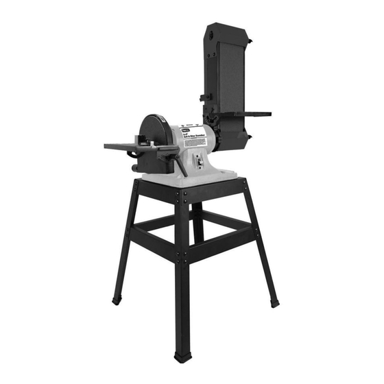
- Page 1 Operating Manual & Parts List 9681121 6 × 9˝ Belt and Disc SANDER with Stand Read carefully and follow all safety rules and operating instructions before first use of this product. 9644210.01-0519...
- Page 2 Model #: ___________________ Serial #: ____________________ Purch. Date: ________________...
-
Page 3: Getting Started
GETTING STARTED SAFETY RULES Structural Requirements For your own safety, read operating Make sure all supporting structures and load attaching devices are instructions manual before operating tool. PROPOSITION 65 WARNING: Some dust created by strong enough to hold your intended loads. If in doubt, consult a using power tools contain chemicals known to the state qualified structural engineer. -
Page 4: Specifications
• Make sure the tool is secured to a steady, flat working surface. SAFETY RULES (CONTINUED) When used with a stand, make sure the stand is bolted to a flat surface to prevent tipping over. Tool Should Be Maintained • Support workpiece with tool rest. - Page 5 Assemble Disc Table ASSEMBLY Refer to Figure 2. Refer to Figures 1, 2 and 6, page 10. 1. Attach disc guard to end shield using three pan head screws, three flat washers and three lock washers. Do not attempt to operate tool until it is 2.
-
Page 6: Installation
• Where a 2-prong wall receptacle is encountered, it must be INSTALLATION replaced with a properly grounded 3-prong receptacle installed in accordance with National Electric Code and local codes and Refer to Figures 3, 4 and 5. ordinances. All electrical connections must be This work should be performed by a performed by a qualified electrician. -
Page 7: Electrical Connections
• For optimum performance do not stall motor or reduce speed. INSTALLATION (CONTINUED) Do not force the work into the abrasive. • Support workpiece with tool rest when grinding with belt/disc. Electrical Connections • Never push a sharp corner of workpiece rapidly against belt/disc. - Page 8 Replacing Abrasive Disc OPERATION (CONTINUED) Refer to Figure 6, page 10. Adjust Belt Table 1. Remove disc table and dust chute (Ref. Nos. 4 and 8). Remove old abrasive disc by peeling it from the aluminum disc. Refer to Figure 6, page 10. Removing aluminum disc from motor shaft is not necessary.
-
Page 9: Maintenance
Lubrication MAINTENANCE • The shielded ball bearings in this tool are permanently lubricated at the factory. They require no further lubrication. Make certain that the unit is disconnected • When operation seems stiff, a light coat of paste wax applied to from power source before attempting to the belt table and disc table will make it easier to feed the work service or remove any component. -
Page 10: Troubleshooting Guide
TROUBLESHOOTING GUIDE Symptom Possible Cause(s) Corrective Action Motor will not start. 1. Blown line fuse or tripped circuit 1. If fuse is blown, replace with fuse of proper breaker. size. If breaker tripped, reset it. 2. Low line voltage. 2. Check power supply for voltage and correct as needed. - Page 11 NOTES...
- Page 14 REPAIR PARTS ILLUSTRATION FOR STAND Figure 7 – Replacement parts illustration for stand.
- Page 15 REPAIR PARTS LIST FOR STAND Ref. Part Description Number Qty. Top Frame 9636351.00 Brace 9636352.00 9636353.00 Foot 9636354.00 Carriage bolt M6 × 12 Flat washer M8 Hex Nut M8 Hex head bolt M8 × 55 Flange Nut M6 (∆) Not shown. (▲) Not included. (N/A) Not available as replacement part.
- Page 16 NORSE Operating Manual & Parts List 9681121 NORSE WARRANTY NORSE by C.H. Hanson warrants their products to be free of defects in material or workmanship. This warranty does not cover defects due directly or indirectly to misuse, abuse, normal wear and tear, failure to properly maintain the product, heated, ground or otherwise altered, or used for a purpose other than that for which it was intended.
Need help?
Do you have a question about the Norse 49G990B and is the answer not in the manual?
Questions and answers
What is part #42?
Part #42 is a Flat Washer M6 (2 pieces).
This answer is automatically generated