Table of Contents
Advertisement
Quick Links
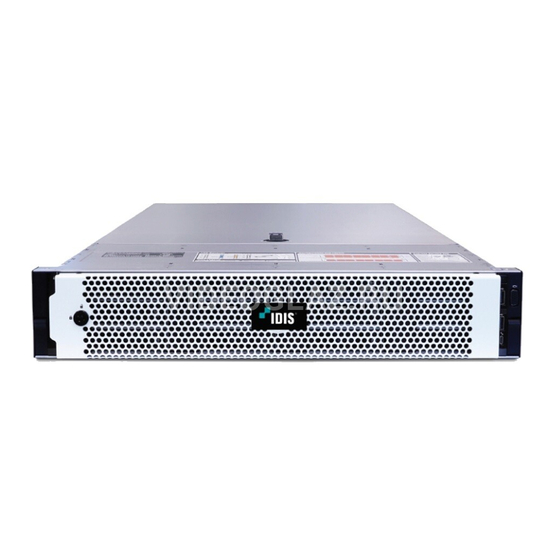
IR-1100
Quick Guide
Version 1.0.0
© IDIS Co., Ltd. All rights reserved. IDIS and identifying product names and numbers herein are registered trademarks of IDIS Co., Ltd.
All non-IDIS brands and product names are trademarks of their respective companies.
Product appearance, build status and/or specifications are subject to change without notice.
Advertisement
Table of Contents

Related Manuals for Idis IR-1100


Summary of Contents for Idis IR-1100
- Page 1 Quick Guide Version 1.0.0 © IDIS Co., Ltd. All rights reserved. IDIS and identifying product names and numbers herein are registered trademarks of IDIS Co., Ltd. All non-IDIS brands and product names are trademarks of their respective companies. Product appearance, build status and/or specifications are subject to change without notice.
- Page 2 ⓒ 2020 IDIS Co., Ltd. IDIS Co., Ltd. reserves all rights concerning this manual. Use or duplication of this manual in part or whole without the prior consent of IDIS Co., Ltd. is strictly prohibited. Contents of this manual are subject to change without prior notice..
-
Page 3: Table Of Contents
Getting Started ............................. 14 Setting Windows OS..........................14 Setting Built-in SSD Storages ....................... 16 Setting Recording Drives ........................17 Installing IDIS Solution Suite ......................... 33 Teaming Network Interface Controller(NIC) ..................34 Licenses and Service Codes ......................40 Windows OS License ..........................40 IDIS Solution Suite License ........................ -
Page 4: Introduction
This NVR (Network Video Recorder) unit offers the following features: Tested and validated with IDIS Solution Suite up to 256 Full HD H.264/H.265 IP cameras Supports up to 256 Full HD cameras in real-time for enterprise-level surveillance systems ... -
Page 5: Accessories
Upon unpackaging the product, check the contents inside to ensure that all the following accessories are included. Component Quantity IR-1100 Main Body Front Chassis & Lock Key Safety, Environmental, and Regulatory Information Manual Power Code (A Type- Deskside) Power Jumper Code (10A,4M,C13/C14) -
Page 6: Overview
Quick Guide IR-1100 Overview 3.1 Dimension 482.0 mm (18.98 inch) 86.8 mm (3.42 inch) 717.6 mm (28.25 inch) 3.2 Front Panel Item Component Description Contains system health and system ID, status LED and optional Left control panel iDRAC Quick Sync 2 (wireless). - Page 7 Quick Guide IR-1100 3.2.1 Left control panel Item Indicator Icon Description Indicate the status of the system. Status LED The indicators display solid amber if any error occurs. For more information, see Status LED indicators. Indicates the system health. System health...
- Page 8 Quick Guide IR-1100 The indicator turns solid Restart the system. Update any required PCIe amber if a PCIe card drivers for the PCIe card. Reinstall the card. experiences an error. (2) System Health and System ID indicator Indicator code Condition...
- Page 9 Quick Guide IR-1100 3.2.2 Drive slots Each drive carrier has an activity LED indicator and a status LED indicator. Item Component Icon Description Drive status indicator Indicates the power condition of the drive. Drive activity indicator Indicates whether the hard drive is currently in use or not.
- Page 10 Quick Guide IR-1100 3.2.3 Right control panel Item Indicator Icon Description Indicates if the system is turned on or off. Press the power Power button button to manually turn on or off the system. The USB ports are 4-pin, 2.0-compliant. These ports enable USB port (2) you to connect USB devices to the system.
-
Page 11: Rear Panel
Quick Guide IR-1100 3.3 Rear Panel Item Component Icon Description Full-height PCIe The PCIe expansion card slot (riser 1) connects up to three expansion card slot full-height PCIe expansion cards to the system. Half-height PCIe The PCIe expansion card slot (riser 2) connects one half- expansion card slot height PCIe expansion cards to the system. - Page 12 Quick Guide IR-1100 Indicator code Condition Link and activity indicators are off The NIC is not connected to the network. Link indicator is green and activity The NIC is connected to a valid network at its maximum port indicator is blinking green speed and data is being sent or received.
-
Page 13: Front Bezel
Quick Guide IR-1100 3.4 Front Bezel A key is located at the backside of the front bezel. You can secure recording storages by locking the lock on the front side of the bezel. Version 1.0.0... -
Page 14: Getting Started
Getting Started 4.1 Setting Windows OS 4.1.1 Setting password Default login details for IR-1100 are as follows. ID: Administrator Password: P@ssw0rd Log in with the login detail above, and make sure to change the password for security. (1) Click ‘Windows Setup > Control Panel > User Accounts > Manage another account’. - Page 15 4.1.2 Activating Windows OS license Windows on the IR-1100 is basically activated when it is dispatched. Windows OS must be activated in the following picture. If your Windows OS is not activated, please refer to ‘Checking Windows OS Key’ and activate your Windows OS with your Windows OS Key.
-
Page 16: Setting Built-In Ssd Storages
4.2 Setting Built-in SSD Storages Two 240GB SSDs are located inside of IR-1100. Typically, the SSDs are on RAID 1 level which appears to be a single drive. Windows OS is installed on this drive and IDIS Solution Suite installation package is located on the same drive as well. -
Page 17: Setting Recording Drives
Quick Guide IR-1100 4.3 Setting Recording Drives 4.3.1 Installing Recording Drives Maximum 8 of 3.5” HDD can be attached to the Drive slots of System.. Drives for recording purposes can be installed by the procedure below. (1) Insert the 3.5 inch drive adapter into the drive carrier with the connector end of the drive toward the back of the drive carrier. - Page 18 Quick Guide IR-1100 4.3.2 Configuring RAID Configuring RAID for recording HDD can be done by entering System Setup menu from the boot up process. (1) Press F2 while system is booting up, then select ‘Entering System Setup’ from the BIOS configuration screen.
- Page 19 Quick Guide IR-1100 (3) Select ‘Integrated RAID Controller 1:Dell <PERC H740 Mini> Configuration Utility’. (4) Select ‘Dashboard View > Main Menu’. Version 1.0.0...
- Page 20 Quick Guide IR-1100 (5) Select ‘Configuration Management > Create Virtual Disk’. (6) Configure the main elements from ‘Create Virtual Disk’ menu. Select RAID Type. Version 1.0.0...
- Page 21 Quick Guide IR-1100 You can select HDDs for your RAID level by ticking HDDs from ‘Select Physical Disk’. After selecting the desired HDDs, press ‘Apply Changes’. Insert information of HDDs at ‘Virtual Disk Name’ and check if the Virtual Disk Size is correct.
- Page 22 Quick Guide IR-1100 After configuration, run ‘Create Virtual Disk’. Version 1.0.0...
- Page 23 Quick Guide IR-1100 (7) Check the virtual disk is configured correctly at ‘Main Menu > Virtual Disk Management’ screen. (8) Finish the ‘System Setup’ by clicking ‘Finish’ button at ‘Main Menu’. Version 1.0.0...
- Page 24 To expand recording storage, an external storage such as IS-1100 can be used. To attach the external storage, PCIe type external storage controller card should be attached to IR-1100. To connect with IS-1100, attaching ‘PERP H840 Adapter’ or similar Storage Controllers are recommended.
- Page 25 Quick Guide IR-1100 (2) You will see the inside of the device and the storage controller will be located where the red box is. (4) Align the card-edge connector with the connector on the system board. Press the card-edge down until the card is fully seated in the connector (5) Connect the SAS data cable connectors to the card.
- Page 26 Quick Guide IR-1100 (2) Select ‘System Setup Main Menu > Device Settings’. Version 1.0.0...
- Page 27 Quick Guide IR-1100 (3) Select ‘RAID Controller in Slot 2:Dell PERC <PERC H840 Adapter > Configuration Utility’. (4) Select ‘Dashboard View > Main Menu’. Version 1.0.0...
- Page 28 Quick Guide IR-1100 (5) Select ‘Configuration Management > Create Virtual Disk’. (6) Configure the main elements from ‘Create Virtual Disk’ menu. Select RAID Type. Version 1.0.0...
- Page 29 Quick Guide IR-1100 You can select HDDs for your RAID level by ticking HDDs from ‘Select Physical Disk’. After selecting the desired HDDs, press ‘Apply Changes’. Insert information of HDDs at ‘Virtual Disk Name’ and check if the Virtual Disk Size is correct.
- Page 30 Quick Guide IR-1100 After configuration, run ‘Create Virtual Disk’. Version 1.0.0...
- Page 31 Quick Guide IR-1100 (7) Check the virtual disk is configured correctly at ‘Main Menu > Virtual Disk Management’ screen. (8) Finish the ‘System Setup’ by clicking the ‘Finish’ button at ‘Main Menu’. Version 1.0.0...
- Page 32 Quick Guide IR-1100 (9) After the Windows OS boot up, you can see the information on the newly created Virtual Disk at ‘Windows Setup > Disk Management’ menu. Version 1.0.0...
-
Page 33: Installing Idis Solution Suite
IDIS Solution Suite installation package is on the system and the installation process is as the below. (1) Check the version of IDIS Solution Suite(name of the folder) from the Desktop of Windows OS and also check if sub-folders are included. -
Page 34: Teaming Network Interface Controller(Nic)
IR-1100 4.5 Teaming Network Interface Controller(NIC) IR-1100 has four RJ45 ports and users can use different teaming modes. Network adapter teaming is a term that is used to describe various methods of combining multiple network connections to increase throughput or provide redundancy. - Page 35 Quick Guide IR-1100 4.5.1 Setting NIC Teaming Port (1) Run Server Manager from Start Menu. (2) Go to Local Server. (3) Go to NIC Teaming setup menu. Version 1.0.0...
- Page 36 Quick Guide IR-1100 (4) Click ‘Tasks’ and select ‘Add to New Team’. (5) Set name and desired ports. Version 1.0.0...
- Page 37 Quick Guide IR-1100 4.5.2 Setting NIC Teaming Type (1) Additional settings can be done on the ‘Additional properties’ section. Set options for your desired Teaming setting and click the OK button. The picture below shows available options. (2) Teaming mode: select desired Teaming mode...
- Page 38 Quick Guide IR-1100 4.5.3 Setting LACP Teaming Mode. (1) Go to Add to New Team setup and set as the picture below. (2) Wait until the new setting is saved. Your current network setting will be lost (e.g. IP settings).
- Page 39 Quick Guide IR-1100 4.5.4 Setting Failover Teaming Mode (4) Go to Add to New Team setup and set as the picture below. (5) Wait until the new setting is saved. Your current network setting will be lost(e.g. IP settings) Version 1.0.0...
-
Page 40: Licenses And Service Codes
Quick Guide IR-1100 (6) Check the result. Licenses and Service Codes 5.1 Windows OS License Windows OS Key is required for certifying the reinstalled Windows OS and you can find it as follows. (1) Find the Windows OS Key on the top chassis of the product. -
Page 41: Idis Solution Suite License
5.2 IDIS Solution Suite License IDIS Solution Suite License is not included in this product. It will be delivered separately by the seller. If you need to re-activate License due to an abnormal situation(e.g. changing server), please refer to manuals in IDIS Solution Suite installation folder on your desktop of Windows OS. -
Page 42: Specification
Quick Guide IR-1100 Specification SYSTEM IDIS Solution Suite Compatible with Expert and Federation/Version 2.6.0 or Higher Network Connection 4 GbE RJ-45 Ports (1000Base-T) Recording Data Rate Up to 1024Mbps (128MBps) Number of Cameras Up to 256 Recording Storage 8 Bay... - Page 43 Quick Guide IR-1100 CERTIFICATIONS Emissions Classification FCC Rating Class A CISPR 22; EN55022; EN55024; FCC CFR 47; Pt 15; ICES-003; CvNS14336-1; CNS13438; GB4943; GB9254; EN 61000-3-2; EN61000-3-3 Directives RoHS, Reach(SVHC), WEEE Version 1.0.0...
-
Page 44: Warranty
Quick Guide IR-1100 Warranty The warranty period for this product is 3 years. Version 1.0.0...
Need help?
Do you have a question about the IR-1100 and is the answer not in the manual?
Questions and answers