Advertisement
Advertisement

Related Manuals for Benchmark MyTemp Mini CO2


Summary of Contents for Benchmark MyTemp Mini CO2
- Page 1 Operations Manual...
-
Page 2: Table Of Contents
CONTENTS PAGE GENERAL INFORMATION ON PRECAUTION CONFIGURATION FEATURES AND SPECIFICATIONS INSTALLATION OPERATION SERVICE AND CONTACT Page 2 / 12... -
Page 3: General Information On Precaution
1. General Information and Precautions Safety Symbols: 1.1. Precautions related to the power cable Always leave at least 3cm between the power cable and the back wall to ensure that the power cable is not pressed to firmly against the power inlet. Always use the power supply and plug that was supplied with this product. - Page 4 Please check the voltage & Hertz written on serial label. (Over-voltage, under-voltage can damage the product and poor performance.) When you install the product, you have to put the distance of at least 30cm from the wall. To completely separate the unit from the power supply, power plug must be disconnected.
-
Page 5: Configuration
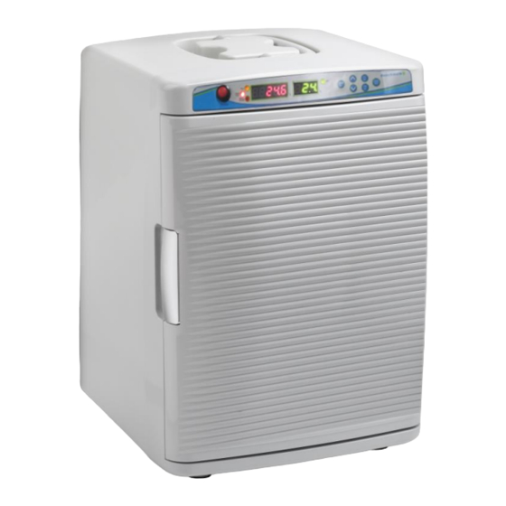
2. Configuration. Figure 1. Front side Handle for transport Control panel Door Handle Support, for closing the door Figure 2. Inner Chamber Duct for Air flow IR CO₂ sensor Stainless Steel shelf Air Circulation Fan Water Container for Humidity Page 5 / 12... - Page 6 Figure 3. Back of Incubator Ventilation Fan CO₂ Sample Port Serial Label CO₂ Inlet Port Non-Slip Rubber Feet DC12V Power Inlet Do not confuse CO₂ Inlet Port and Sample Port. Tube from gas cylinder must be connected to CO ₂ Inlet Port. Sample Port is used to check the CO₂ density with an external analyzer. Figure 4.
-
Page 7: Features And Specifications
3. Features and Specifications 3.1. Features 1. Light weight, compact and portable. 2. Precise temperature control by Peltier. (ambient -10’C, lowest temp. is 15’C at 25’C RT) 3. Advanced air circulation for improved uniformity 4. Natural Humidification System with included water tray 5. -
Page 8: Installation
4. Installation Before beginning the installation, always: Inspect the packaging for damage – When the instrument is received, inspect the item carefully to check any transit damage. In the event of damage, always report the damage to the shipping carrier and your local representative immediately. -
Page 9: Operation
3. Connect the CO₂ Gas supply The Gas tubes provided are combined with 4mm (dia.) and 6mm (dia.) tube. Insert the 4mm edge of tube to gas inlet port and connect 6mm edge of tube to gas regulator which is installed on the cylinder or gas line in your lab. - Page 10 5.4 Calibration for temperature and CO2 In the event that recalibration is required for the temperature or CO2 percentage, please follow procedure below: Measure CO₂ density and Temperature after incubator is stabilized (after 2 hours of having reached the desired settings) a.
- Page 11 d. The fourth channel is the “CAL SET” ☞ CO2 density calibration Channel 4 is at CO2 density calibration stage. Press UP (▲) to increase the setting by as much as the difference between the measured value and the displayed value. Press DOWN (▼) to decrease the setting by as much as the difference between the measured value and the displayed value.
-
Page 12: Service And Contact
- Pressing mute button when door open will temporarily delay the alarm for 3 minutes. 6. Service and Contact Service on the instrument should only be performed by qualified service personnel. To request service or technical support, please contact Benchmark Scientific or your local Benchmark Scientific representative. Ph: +1-908-769-5555 Fax: +1-732-313-7007 Em: Info@BenchmarkScientific.com...
Need help?
Do you have a question about the MyTemp Mini CO2 and is the answer not in the manual?
Questions and answers