Table of Contents
Advertisement
Advertisement
Table of Contents

Related Manuals for Oki ColorPainter M-64S


Summary of Contents for Oki ColorPainter M-64S
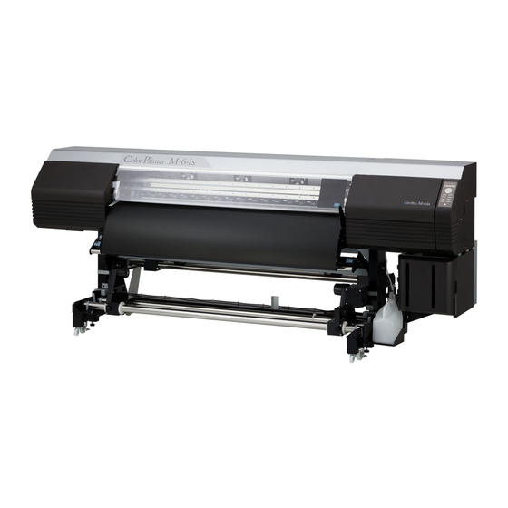
- Page 1 User's Guide ColorPainter M-64s Traffic Sign Printer with 3M™ SX Ink...
- Page 2 The contents of this manual may be changed without prior notice. Oki Data Corporation. reserves the right to make changes without notice to the specifications and materials contained herein and shall not be responsible for any damage (including consequential) caused by reliance on the materials presented, including but not limited to typographical, arithmetic, or listing errors.
-
Page 3: Introduction
Introduction This document describes the process of printing on reflective sheeting. For explanations on how to use the other functions of the printer, refer to the IP-6620 Color Inkjet Printer User’s Guide. The following items should be read before using the external dryer system to ensure correct and safe operations of this system. - Page 4 When you want to... Install the re ective sheeting. Unfold the dust cover. page 24 page 29 Install the take-up reel unit. Install the external dryer system. page 34 page 39 Print from the RIP software. Remove the printout from the take-up reel unit.
-
Page 5: Table Of Contents
Table of Contents Maintenance Introduction ............. Table of Contents ..........Daily maintenance ......... Safety precautions ........... Extra ionizers maintenance ........Symbol on the printer ........Edge sensors cleaning ..........Manual legend (Notational rules) ....Dust cover cleaning ..........Components delivered with the printer ..Operating conditions ........ -
Page 6: Safety Precautions
Safety precautions The following symbols are used in this document to ensure proper operation of the external dryer system and to prevent this system from being damaged. Follow the instructions marked with these symbols: Failure to follow the guidelines marked with WARNING this symbol could result in serious personal injury or death. - Page 7 WARNING Be sure to read warnings below before use. Use the power supply voltage specified on the nameplate. Turn off the printer, unplug the power cord from the Avoid overloading the electrical outlet used for the printer power outlet, and contact your service representative in with multiple devices.
- Page 8 If the cover is not cleaned regularly, the paint on the cover surface may get damaged. 5. Always use OKI Data specified accessories and options. Products not specified by OKI Data may degrade the image quality, cause a malfunction, and make maintenance impossible.
- Page 9 4. Unpack the Oki Data ink cartridges only to install them. Do not store Oki Data ink cartridges in direct sunlight. Store the Oki Data ink cartridges in a cool, dry place. This prevents deterioration of the ink during storage.
- Page 10 Precautions when handling printouts Do not touch the printed surface of the media before the ink dries, or especially 24 hours after printing. Handle the printout by the margins. Do not scratch the printout to avoid lost or transfer of colors. To avoid color transfer, do not stack printed media on one another with their printed surface facing in contact.
-
Page 11: Manual Legend (Notational Rules)
Manual legend (Notational rules) The notational rules used for explanation in this guide are as follows: Marks WARNING ‹ Boxes marked with a WARNING describe points of caution to avoid serious personal injury. CAUTION ‹ Boxes marked with a CAUTION describe points of caution to avoid injury to yourself or damage to the printer. TIP: š... -
Page 12: Components Delivered With The Printer
Components delivered with the printer Check that the following items are contained in the reflective sheeting kit. If an item is missing or damaged, please contact your dealer or a service representative. External dryer system <x1> Dust cover <x1> Extra ionizers Bar type ionizer <x1>... -
Page 13: Operating Conditions
Operating conditions Installation and maintenance space Adequate space is required around the printer for replacement of consumables and parts, print processing, and ventilation during normal operation and maintenance. Secure the space shown in the figure below. 3900 *6100 1000 *1500 *1500 4300 (Front side) 2000 Secure 2200 mm in the horizontal direction. -
Page 14: Environmental Conditions
Environmental conditions Operating temperature and humidity levels Refer to the IP-6620 Color Inkjet Printer User’s Guide. Places where the printer should not be installed Do not install the printer in the following places. Places near a fire Places exposed to direct sunlight Places subject to vibration Places with excessive dust Places subject to extreme changes in temperature or humidity... -
Page 15: Before Printing
Before printing... -
Page 16: Appearance / Main Components And Their Functions
Appearance / Main components and their functions Printer front (take-up side) Control box Controls the external dryer system and the bar type ionizer. The state (lit, blinking, off) of the LEDs of the control box indicates the status of the external dryers and the bar type ionizer. -
Page 17: Printer Rear (Supply Side)
Printer rear (supply side) Bar type ionizer Removes static electricity from the reflective sheeting. (Operates only when printing on reflective sheeting.) Dust cover Makes it more difficult for dust to adhere to the media. Printer interior Extra ionizers Removes static electricity from the media and reduces print defects caused by ink mist. -
Page 18: To Turn The Control Box On And Off
To turn the control box on and off The power supply must be 200 V. POWER SUPPLY POWER SSR 1 POWER SSR 2 POWER Off CAUTION ‹ Use only the power cords supplied with the control box. ‹ The supplied power cable is for 200 V AC only. Note that the plug shape differs from that for 100 V AC. Power-on procedure Turn the printer on before turning the control box on. - Page 19 Turn the POWER SUPPLY POWER on. Turn on the SSR 1 POWER and SSR 2 POWER. CAUTION ‹ When turning the control box on, the self-check function may take up to three minutes to complete in case the external heaters are hot. Before printing...
-
Page 20: Power-Off Procedure
Power-off procedure Turn off the SSR 1 POWER and SSR 2 POWER. Turn the POWER SUPPLY POWER off. Turn the printer off. page 38 in the IP-6620 Color Inkjet Printer Refer to User’s Guide. Before printing... -
Page 21: Supported Media
Supported media Reflective sheeting Media used to print traffic signs. Usually, glue on the back of the media makes it possible to stick it after removing the release paper. Ask your dealer for more details. Before printing... -
Page 22: Precautions And Restriction Regarding The Use Of Reflective Sheeting
Precautions and restriction regarding the use of reflective sheeting Colored media When printing on colored media, the printer may not be able to automatically identify the media width depending on the color, and a media mismatch error may occur. Media not supporting automatic media identification The automatic media identification function uses the edge sensors to identify the media and determine if reflective sheeting is used before printing. -
Page 23: Printing On Reflective Sheeting
Printing on reflective sheeting... -
Page 24: Loading The Media On The Printer
Loading the media on the printer Procedure to load roll media Open the front cover and place the right and left edge guards at each extremity of the platen. Close the front cover. Notes ‹ The media edge guards are put aside to avoid any contacts with the roll ends when loading the media. - Page 25 Move the capping unit side media holder fully to the left. Move the maintenance area side media holder fully to the right. Install the media jack and media support. š Since the left side of the media will be installed first, install the media jack on the capping unit side and the media support on the maintenance side.
- Page 26 Load the media onto the media jack and media support. Notes ‹ Be careful not to drop the media when loading it onto the media jack. ‹ Do not let the media jack fall. Otherwise it may be damaged during use. ‹...
- Page 27 Turn the media jack’s handle counter- clockwise to remove the jack. Then install it to the right side of the roll. Adjust the roll level using the media jack and insert the right media holder into the roll the same way as you did for the left side. Turn the media jack’s handle counter- clockwise to lower and remove the jack.
- Page 28 Feed the media approximately 80 cm between the pressure roller and the grit roller. The printer emits a sound when the media leading edge comes out from the front cover. Notes ‹ Depending on the environment, the media may stick to the paper guide and have difficulty to advance.
- Page 29 Turn the knob screws on both media holders to secure them. While keeping your hand on the media to straighten it, turn the flange to wind the media until only 20 cm comes out from the front cover. Notes ‹ Do not try to forcibly align the media with the gradations lines but install the media parallel to the roll.
- Page 30 Open the front cover and place both edge EDGE GUARDS POSITION guards on the media edges. Place the media edges in the notches on the edge guards. Then close the front cover. Check that the edge guards do not go under the media, or that the media advance smoothly in case of particularly thick media.
- Page 31 Set the amount of remaining media. ENTER REMAIN MEDIA Set the amount of remaining media and press the OK 07: XXX.X YYY.Ym button. To register the amount of remaining media The menu used to set the amount of remaining media is displayed only when ON is set for REMAIN MEDIA MONIT in the media preset menu.
- Page 32 š You can recover the media mismatch error by pressing any button. The following warning is displayed if no action is carried out (the printer emits also a warning beep every minute). CHECK REFLECTIVE SHEET MODE STATUS Printing can be performed with the error message displayed, but follow the procedure below if you want to stop the warning beep.
-
Page 33: Procedure To Monitor Remaining Media
Press the Down button to select OFF. >>>>MEDIA MISMATCH Press the OK button. >>>>MEDIA MISMATCH >>>>MEDIA MISMATCH Notes ‹ After the media has been installed, check that the media does no enter the gap formed by the cutter blade (option) or that it is not caught in the media clips (options). -
Page 34: Setting The Media On The Take-Up Reel Unit
Setting the media on the take-up reel unit Always use the take-up reel unit when printing on reflective sheeting. However, the take-up reel unit may not be used for test printing. Note ‹ If printing is performed without using the take-up reel unit, the performance of the drying operation cannot be guaranteed. -
Page 35: Procedure To Set The Media On The Tur Unit
Procedure to set the media on the TUR unit Put the take-up direction switch installed on the right media holder in the off position. Inner take-up Winding off Outer take-up Move the guide bar to the standby position. Hold the front pipe of the TUR unit by the center and pull the TUR unit toward you. - Page 36 Insert the right flange into one end of a paper tube. Move the left flange and insert it into the other end of the paper tube. Tighten the knob screw on the left flange to secure the position. Feed the media until the leading edge reaches the paper tube.
- Page 37 Maintain the media stretched and attach it to the paper tube with some adhesive tape. Adhesive tape Notes ‹ Attach the media with three pieces of tape, one at the center and one at both the right and left edges. ‹...
- Page 38 Set the take-up direction switch. In loose mode, always select outer take-up direction. Refer to the figure below to set the switch. Inner take-up Winding off Outer take-up Printing on reflective sheeting...
-
Page 39: Installing The External Dryer System
Installing the external dryer system External dryer system installation procedure Install the external dryer system to the printer. WARNING ‹ The location on the front of the printer and the external dryer system where the high temperature warning sticker is affixed becomes very hot. Never touch this location. Otherwise, there is a risk of burn. Place the external dryer system near the front Handles of the printer. -
Page 40: Printing From The Rip Software
The following describes how to specify the colors of traffic signs designed using the FlexiPRINT & CUT Authorized 3M Traffic Edition for OKI software by SAi with spot colors. Click the FlexiPRINT & CUT Authorized 3M Traffic Edition for OKI 12 icon to launch the software. -
Page 41: Traffic Color Specification Procedure
Traffic color specification procedure This procedure describes how to color a target color object in FlexiPRINT & CUT Authorized 3M Traffic Edition for OKI using a traffic color. Select View Filter in the View menu. In the View Filter screen, click Show None and select the target color. -
Page 42: Procedure To Set A Traffic Color To A Target Object
Procedure to set a traffic color to a target object This procedure describes how to select a specific traffic color for a target object when it is difficult to color an object because it is masked by a layer or otherwise grouped. Click the icon to launch the program, and then open the design file from the File menu. -
Page 43: Color Trapping/Choking Feature
This feature is to address ink bleeding of traffic colors printed on retroreflective sheeting, by applying color trapping on the design and then shrinking the shapes. Open the design into FlexiPRINT & CUT Authorized 3M Traffic Edition for OKI. Open the RIP and Print dialog for output. Switch to the Advanced Options tab, select the “choke spot color objects”... -
Page 44: Sending Data From The Design Tool To The Rip Software
Sending data from the design tool to the RIP software This procedure describes how to print traffic signs designed in FlexiPRINT & CUT Authorized 3M Traffic Edition for OKI. With the file of the traffic sign you want to print still open, click the RIP and Print icon. - Page 45 Check the Production Manager screen. Normally, a job is printed when it is added in the Output list. When Hold in list is selected under Send mode in RIP and Print, you may send the data by selecting the job in the Hold list and clicking the Send icon, or by selecting Send from the right-click menu.
- Page 46 Left Margin Right Margin Edge Guards Color Stripe Bar Left Margin 1.000cm 3.260cm 0.500cm 2.760cm Right Margin 1.000cm 1.000cm 0.500cm 0.500cm Follow the procedure below to enter the correct paper size and margin values on the RIP and Print screen that is displayed during printing.
-
Page 47: Drying Operation
Drying operation When printing on reflective sheeting, the drying operation used to dry the ink is performed after the printing operation (scan operation) is completed. The drying operation is carried out until the end of the printout has passed through the external dryer system. Printing operation ends Drying operation ends Take up operation ends... -
Page 48: To Cancel The Drying Operation
The message on the left is displayed during the drying DRYING... operation. REQUIRED TIME YY:YY YY:YY : The remaining time (min:sec, 10 seconds increment) The panel message changes to the message to the left when PRINTER READY the drying operation is complete. 07: RFLTIV/1219mm Notes ‹... -
Page 49: Removing The Media
Removing the media Procedure to print the amount of remaining media The amount of remaining media can be printed on the media before removing the media. š Printing the amount of remaining media before removing it allows you to refer to it to enter the exact amount of remaining media the next time you install the same media. -
Page 50: Procedure To Remove The Roll Media (Output Side)
Procedure to remove the roll media (output side) Notes ‹ Right after printing, the reflective sheeting is extremely hot because it has been warmed by the external dryer system. Wait for a while and check that the reflective sheeting is cool before removing it. ‹... - Page 51 Remove the left side first. ① 1 Turn the media jack’s handle clockwise to raise the media jack to the level of the media. 2 When the jack supports the media, slide the left media holder to remove it from the media roll. Notes ②...
-
Page 52: Procedure To Remove The Roll Media (Feed Side)
Procedure to remove the roll media (feed side) Close the dust cover. Then, fold it and attach it with the five hook-and-loop fasteners. Notes ‹ Hold the pipe with both hands when handling the dust cover. ‹ Pay attention not to catch your fingers when handling the dust cover. - Page 53 Rotate the flange to rewind the media. Loosen the screw fixing the media holder and slide the media holder to remove the media. Notes ‹ If a lot of media remains and the roll is heavy, use tools to help you and remove the media using the loading procedure in the reverse order.
- Page 54 Printing on reflective sheeting...
-
Page 55: Maintenance
Maintenance... -
Page 56: Daily Maintenance
Daily maintenance Perform daily maintenance to maintain the system in good condition and maximize the print quality. The following maintenance operations are required when printing on reflective sheeting. - Extra ionizer cleaning - Edge sensors cleaning - Dust cover cleaning - Cleaning of the sensors for automatic print adjustment - Ionizers cleaning Each part above should be cleaned approximately once per month. -
Page 57: Extra Ionizers Maintenance
Extra ionizers maintenance Perform the maintenance of the extra ionizers when their discharging performance has decreased. Procedure from the printer panel The following procedure explains how to clean the extra ionizers. Press the MAINTENANCE button. PRINTER READY 01: PAPER / 1626mm Press the DOWN button to select CLEAN MAINTENANCE EXTRAIONIZER. - Page 58 Procedure in CP_Manager The following procedure explains how to clean the extra ionizers. Click the Maintenance tab. Click the Extra Ionizers Cleaning button in the Maintenance tab. (To step Maintenance...
- Page 59 The carriage moves to the extra ionizers cleaning area. CARRIAGE IS MOVING PLEASE WAIT The printer issues a warning beep. Carriage stops moving. š When the carriage moves, the printer issues a warning beep. page 198 of the User’s Guide supplied Refer to with your printer.
- Page 60 Remove the fasteners securing the right and left extra ionizers. fasteners fasteners Remove the extra ionizers from the printer. Maintenance...
- Page 61 Slide and remove the louver from each extra ionizer. louver Note ‹ If it is difficult to remove the louvers, it may help to lift them slightly when sliding them. Clean the six discharge needles (circled areas in the picture) inside the extra ionizers using the supplied brush.
- Page 62 Reinstall the louvers to the extra ionizers. Note ‹ The louvers need to be correctly oriented when installed. Make sure that their front side is oriented outward when installing them. Front side (with protrusion) Back side (no protrusion) Louver both sides appearance Incorrect louver installation Incorrect louver installation...
- Page 63 Slide the louver into the ionizer until the arrows match. Install the extra ionizers to the printer, secure them using the fasteners, and then connect the connectors. Close the maintenance area cover and the CLEAN EXTRA IONIZERS front cover. AND CLOSE COVERS CARRIAGE IS MOVING PLEASE WAIT Carriage stops moving.
-
Page 64: Edge Sensors Cleaning
Edge sensors cleaning The precision of the automatic media identification function will decrease if ink mist adheres to the edge sensors. Therefore, it is necessary to clean the sensors periodically. The quantity of ink mist that will adhere to the sensors depends on the print data and the printer usage conditions. - Page 65 Clean the surface of the edge sensors with a Sensors for automatic print adjustment Edge sensors cleaning swab. Ionizers The edge sensors are located at the back of the sensors for automatic print adjustment. Rub gently the surface of the sensors with the cleaning swab to remove the ink mist that adhered.
-
Page 66: Dust Cover Cleaning
Dust cover cleaning Dust that accumulates on the dust cover may adhere to the media and create white or black marks on the printout or other problems related to the print quality. Remove the dust accumulated on the dust cover using a dry soft cloth. When doing so, remove the media from the printer to prevent the dust from adhering to the media. -
Page 67: Advanced Operations
Advanced operations... -
Page 68: Handle The Media
Handle the media Media preset menu Twenty (No. 01 to 20) media presets can be registered in the media preset menu. Note š When printing on reflective sheeting, it is recommended to select the media preset No. 07 during the media installation. ‹... -
Page 69: Media Registration In Cp_Manager
Media registration in CP_Manager The Media Preset tab in CP_Manager is as shown below. (When the reflective sheet mode is set on, the values that are fixed and cannot be modified for printing are grayed out.) Advanced operations... -
Page 70: Heater Operation Of The External Dryer System
Heater operation of the external dryer system Display the control menu of the external dryer system Press the HEATER button to display the heater control menu. In the heater control menu, pressing the HEATER button switches the display between the media heater control menu, the external dryer system control menu and the online state, as shown below. -
Page 71: External Dryer System Control Information
External dryer system control information When Ext is displayed at the bottom left of the panel, press the Up or Down button to change the external dryer system control. Starts preheating of the external dryer system. - Preheating mode: Use this mode to warm the external dryer system in advance. * When printing starts in this mode, the printer switches automatically to the normal operation. -
Page 72: Display In Cp_Manager
Display in CP_Manager The external dryer system warming state is displayed as follows in CP_Manager. The external dryer system warming state is displayed as follows. Display Description The external dryer system is turned off. The external dryer system is on and did not reach the temperature yet WARMING UP (still warming up). -
Page 73: Troubleshooting
Troubleshooting... -
Page 74: When An Error Message Is Displayed
When an error message is displayed When the ERROR LED lights up, check the message displayed on the operation panel. Error messages shown below are classified into two groups. Service call errors: Errors that the operator (customer) cannot recover, such as hardware/software failures. Contact your service representative. - Page 75 <TUR unit errors> Meaning The TUR unit is not installed correctly. CHCK TUR UNIT STATUS Action Check the following on the TUR unit and install it correctly. PRINT? OK/CANCEL Check that the take-up direction switch is set to the outer take-up direction.
- Page 76 Meaning Connectors of both extra ionizers are not connected properly. CHECK R & L EXTRA IONIZERS CONNECTION Action Press any key to clear the error. If this error occurs, check the extra ionizer’s connector (circled in the picture below). If the connector is not connected, connect it while referring to Extra ionizers maintenance in this guide.
-
Page 77: Warning Messages
Warning messages After printing, occasionally you may see one of the following messages appear on the operation panel with the ERROR LED flashing. They are warning messages. In such cases, follow the instructions in the Action rows. Meaning The reflective sheeting setting (reflective sheet mode) of the media CHECK REFLECTIVE preset does not correspond to the type of the media installed in the SHEET MODE STATUS... -
Page 78: When The Red Led (Alarm) Of The Control Box Blinks
When the red LED (alarm) of the control box blinks This LED blinks when an error occurred in the external dryer system. After turning the control box off, check the connection of the cables between the control box and the heaters, as well as the connection of the cable between the control box and the printer. -
Page 79: Menu Tree
Menu tree... - Page 80 PRINTER READY MENU >INFORMATION CHECK MEDIA 01: PAPER / 1626mm INFORMATION WARNING INFO FOR WRINKLES (not printing) MENU >EDIT MEDIA PRESETS >>SELECT PRESET NO. XX: Current media preset number Z: Registration mark (A registration mark * is displayed if the media preset is registered) EDIT MEDIA PRESETS SELECT PRESET NO.
-
Page 81: Appendix
Appendix... -
Page 82: Basic Specifications
Basic specifications Specification / Function Item IP-6620 (reflective sheet mode on) Print method Piezo-type color inkjet printing (main scanning direction) × (subscanning direction) Resolution 540 dpi × 360 dpi × DDP 19.4 m /h for 48-inch width media at 6-pass bidirectional and high density Print speed (STANDARD mode) Media supply/take-up direction... -
Page 83: Consumables
If it is swallowed, do not try to induce vomiting, but consult a doctor. CAUTION ‹ Always use OKI Data specified ink cartridges. Failure to use the recommended ink cartridges may lead to a deterioration of the print quality or a printer malfunction. This may also invalidate your warranty. - Page 84 47260301EE Rev4...
Need help?
Do you have a question about the ColorPainter M-64S and is the answer not in the manual?
Questions and answers
What is the system error 2610