Advertisement
Available languages
Available languages
Quick Links
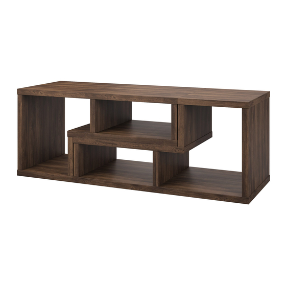
Stock # MS18-D2-1011-02 White
(Optional Configuration)
If you have any questions regarding assembly or if parts are missing, DO NOT return this item to the store
where it was purchased. Please call our customer service number and have your instructions and parts list
ready to provide the model name, part name or factory number:
Or visit our web site 24 hours a day, 7 days a week for product assistance at
THIS INSTRUCTION BOOKLET CONTAINS IMPORTANT SAFETY INFORMATION.
2-Piece Shelf Set
# MS18-D2-1011-03 Canyon Walnut
ADULT ASSEMBLY REQUIRED
Pacific Standard Time: 8:30 a.m. - 4:30 p.m., Monday - Friday
www.whalenstyle.com
Or e-mail your request to parts@whalenfurniture.com
PLEASE READ AND KEEP FOR FUTURE REFERENCE.
Date 2018-04-10 Rev. 0001-A Factory: KONRIC
866-942-5362
LOT NUMBER:
DATE PURCHASED:
/
/
Advertisement

Related Manuals for Mainstays MS18-D2-1011-02


Summary of Contents for Mainstays MS18-D2-1011-02
- Page 1 LOT NUMBER: DATE PURCHASED: 2-Piece Shelf Set Stock # MS18-D2-1011-02 White # MS18-D2-1011-03 Canyon Walnut (Optional Configuration) ADULT ASSEMBLY REQUIRED If you have any questions regarding assembly or if parts are missing, DO NOT return this item to the store where it was purchased.
- Page 2 M A X I M U M R E C O M M E N D E D W E I G H T L O A D S MANUFACTURER: Whalen Furniture Manufacturing CATALOG: 2-Piece Shelf Set MODEL # MS18-D2-1011-02 / MS18-D2-1011-03 MADE IN CHINA MAXIMUM LOAD 135 lb. (61.3 kg) MAXIMUM LOAD 50 lb.
- Page 3 IMPORTANT Before you begin: Open, identify and count all parts prior to assembly. Lay out parts on a flat and non- abrasive surface. You will need the parts identified on page 4 of this instruction manual. NOTE: IT IS VERY IMPORTANT TO USE GLUE WITH DOWELS. EXCESS GLUE CAN BE WIPED OFF WITH DAMP CLOTH.
- Page 4 Parts and Hardware List Please read completely through the instructions and verify th at all listed parts and hardware are present before beginning assembly. A- Large Shelf Panel (Qty. 2) B- Middle Shelf Panel (Qty. 2) C- Small Shelf Panel (Qty. 2) D- Large Side Panel (Qty.
- Page 5 Assembly Instructions Cam Bolt (28 used in this step) ② 1. Unpack the unit and confirm that you have all the hardware and required parts. Assemble the unit on a carpeted floor or the empty carton to avoid any scratch. 2.
- Page 6 Assembly Instructions M10 x 40 mm Wood Dowel Cam Lock (4 used in this step) used in this step ③ ① 3. Insert two Wood Dowels (3) into the inner holes of each Small Side Panel (F) and attach it to the Large Shelf Panel (A) by engaging two Cam Locks (1).
- Page 7 Assembly Instructions M10 x 40 mm Wood Dowel Cam Lock (4 used in this step) used in this step ③ ① 4. Attach one Middle Shelf Panel (B) onto the Small Side Panels (F) with four Cam Locks (1) and four Wood Dowels (3).
- Page 8 Assembly Instructions Cam Bolt (2 used in this step) ② 5. Securely screw the Cam Bolts (2) into the designated small holes on the Middle Shelf Panel (B)
- Page 9 Assembly Instructions Cam Lock M10 x 40 mm Wood Dowel used in this step (2 used in this step) ① ③ 6. Attach the Middle Side Panel (E) to the Middle Shelf Panel (B) with two Cam Locks (1) and two Wood Dowels (3).
- Page 10 Assembly Instructions Cam Lock M10 x 40 mm Wood Dowel used in this step (2 used in this step) ① ③ 7. Attach the Large Side Panel (D) to the Large Shelf Panel (A) with two Cam Locks (1) and two Wood Dowels (3).
- Page 11 Assembly Instructions M10 x 40 mm Wood Dowel Cam Lock (4 used in this step) used in this step ③ ① 8. Attached the Small Shelf Panel (C) to the Side Panels (D and E) with four Cam Locks (1) and four Wood Dowels (3).
- Page 12 Assembly Instructions Cam Lock Cap 16 used in this step ④ 9. Put the Cam Lock Caps (4) to the Cam Locks on the Side Panels (D, E and F) to conceal the Cam Locks. 10. Repeat the same procedure to assemble the other unit.
- Page 13 Assembly Instructions M3.5 x 15 mm Screw Metal Bracket (4 used in this step) (2 used in this step) ⑤ ⑥ 11. Refer to the configuration you desired, stack the two units together making sure they are centered properly and the ends are even with each other. 12.
- Page 14 Assembly Instructions Tools required (not provided): Phillips screwdriver, stud finder, power drill and 3 mm/0.1 in drill bit. 14. Ask for assistance to position the unit at the desired location against a wall. 15. Follow the instructions printed on the plastic bag containing the Tipping Restraint Hardware to attach the tip-over restraints to the unit and the wall.
-
Page 15: Quality Guarantee
Care and Maintenance Use a soft, clean cloth that will not scratch the surface when dusting. Use of furniture polish is not necessary. Should you choose to use polish, test first in an inconspicuous area. Using solvents of any kind on your furniture may damage the finish. ... - Page 17 NÚMERO de LOTE: FECHA de COMPRA: Juego de estanteria de 2 piezas Serie # MS18-D2-1011-02 Blancas # MS18-D2-1011-03 Nogal oscuro (Configuración opcional) ENSAMBLE REQUERIDO POR ADULTO Si tienen alguna pregunta acerca del ensamble o si alguna parte está faltante, no retorne esté producto a la tienda donde lo compró.
- Page 18 M Á X I M O P E S O R E C O M E N D A D O FABRICANTE: Whalen Furniture Manufacturing CATALOGO: Juego de estanteria de 2 piezas MODELO # MS18-D2-1011-02 / MS18-D2-1011-03 HECHO EN CHINA MÁXIMA CARGA 135 lb. (61.3 kg) MÁXIMA CARGA 50 lb.
- Page 19 IMPORTANTE Antes de comenzar: Abra, identifique y cuente todas las partes antes del ensamble. Coloque las piezas sobre una superficie plana y no abrasiva. Tendrá que las partes identificadas en la página 4 de este manual de instrucciones. NOTA: ES MUY IMPORTANTE PARA EL USO DE GOMA CON LOS PERNSO DE MADERA. EL. EXCESO DE PEGAMENTO SE PUEDE LIMPIAR CON UN PAÑO HÚMEDO.
- Page 20 Lista de partes y material de ferretería Por favor lea completamente las instrucciones y verifique que estén todas las partes antes de iniciar el ensamblado. A- Balda grande ( B- Balda mediana ( C- Balda pequeña ( Cant. Cant. Cant. D- Módulo lateral grande (Cant.
-
Page 21: Instrucciones De Ensamblaje
Instrucciones de ensamblaje Perno de fijación (28 usados en este paso) ② 1. Desempacar la unidad y confirmar que se tiene todo el material de ferretería y partes requeridas. Ensamblar la unidad en un piso alfombrado o en el cartón vacío para evitar rasguños. 2. - Page 22 Instrucciones de ensamblaje Clavija de madera de M10 x 40 mm Tuerca de fijación (4 usadas en este paso) usadas en este paso ① ③ 3. Introduzca dos clavijas de madera (3) en los agujeros interiores de cada módulo lateral pequeño (F) y únalo a la balda grande (A) uniendo dos tuercas de fijación (1).
- Page 23 Instrucciones de ensamblaje Tuerca de fijación Clavija de madera de M10 x 40 mm (4 usadas en este paso) (4 usadas en este paso) ① ③ 4. Una la balda mediana (B) a los módulos laterales pequeños (F) con cuatro tuercas de fijación (1) y cuatro clavijas de madera (3).
- Page 24 Instrucciones de ensamblaje Perno de fijación (2 usados en este paso) ② 5. Fije fuertemente los pernos de fijación (2) en los agujeros pequeños designados en la balda mediana (B).
- Page 25 Instrucciones de ensamblaje Clavija de madera de M10 x 40 mm Tuerca de fijación (2 usadas en este paso) usadas en este paso ③ ① 6. Una el modulo lateral mediano (E) a la balda mediana (B) con dos tuercas de fijación (1) y dos clavijas de madera (3).
- Page 26 Instrucciones de ensamblaje Clavija de madera de M10 x 40 mm Tuerca de fijación (2 usadas en este paso) usadas en este paso ① ③ 7. Una el módulo lateral grande (D) a la balda grande (A) con dos tuercas de fijación (1) y dos clavijas de madera (3).
- Page 27 Instrucciones de ensamblaje Tuerca de fijación Clavija de madera de M10 x 40 mm usadas en este paso (4 usadas en este paso) ① ③ 8. Una las baldas pequeñas (C) a los módulos laterales (D y E) con cuatro tuercas de fijación (1) y cuatro clavijas de madera (3).
- Page 28 Instrucciones de ensamblaje Embellecedor 16 usados en este paso ④ 9. Coloque el embellecedor (4) en las tuercas de fijación de los módulos laterales (D, E y F) para ocultar las tuercas de fijación 10. Repita el mismo procedimiento para ensamblar la otra unidad...
- Page 29 Instrucciones de ensamblaje M3.5 x 15 mm Tornillo Soporte metálico (4 usados en este paso) (2 usados en este paso) ⑤ ⑥ 11. Refiérase a la configuración elegida, apilar ambas unidades juntas asegurar de que este correctamente centrado y que los extremos estan igualados el uno con el otro. 12.
- Page 30 Instrucciones de ensamblaje (no incluidas): Desarmador estrella, buscador de estudios, taladro Herramientas adicionales requeridas y broca de 3 mm/0.1 pulgadas. 14. Pedir asistencia para posicionar la unidad ensamblada en posición vertical y en el lugar deseado contra la pared. 15. Seguir las instrucciones impresas en la bolsa de plástico que contiene el juego de restricción de movimiento para adjuntar los topes de movimiento a la unidad y pared.
- Page 31 Mantenimiento y Cuidados Use una toalla suave y limpia para evitar daños y rayones. Uso de cera para pulir muebles no es necesario. Si desea usar cera, pruébela en un área que no sea visible para revisar su funcionamiento. ...
Need help?
Do you have a question about the MS18-D2-1011-02 and is the answer not in the manual?
Questions and answers