Table of Contents
Advertisement
Quick Links
A V T E C H
E L E C T R O S Y S T E M S
L T D .
N A N O S E C O N D
W A V E F O R M
E L E C T R O N I C S
S I N C E
1 9 7 5
info@avtechpulse.com
Tel: 888-670-8729 (USA & Canada) or +1-613-686-6675 (Intl)
BOX 5120, LCD MERIVALE
http://www.avtechpulse.com/
Fax: 800-561-1970 (USA & Canada) or +1-613-686-6679 (Intl)
OTTAWA, CANADA K2C3H5
INSTRUCTIONS
MODEL AVR-D2-B
MIL-PRF-19500 SWITCHING TIME TEST
PULSE GENERATOR
WITH IEEE 488.2 AND RS-232 CONTROL
SERIAL NUMBER:
13913
Advertisement
Table of Contents

Related Manuals for Avtech AVR-D2-B


Summary of Contents for Avtech AVR-D2-B
- Page 1 Tel: 888-670-8729 (USA & Canada) or +1-613-686-6675 (Intl) BOX 5120, LCD MERIVALE http://www.avtechpulse.com/ Fax: 800-561-1970 (USA & Canada) or +1-613-686-6679 (Intl) OTTAWA, CANADA K2C3H5 INSTRUCTIONS MODEL AVR-D2-B MIL-PRF-19500 SWITCHING TIME TEST PULSE GENERATOR WITH IEEE 488.2 AND RS-232 CONTROL SERIAL NUMBER: 13913...
-
Page 2: Warranty
Avtech product is found to be defective, Avtech shall at its option repair or replace said defective item. This warranty does not apply to units which have been dissembled, modified or subjected to conditions exceeding the applicable specifications or ratings. -
Page 3: Table Of Contents
TABLE OF CONTENTS WARRANTY........................2 TECHNICAL SUPPORT....................2 TABLE OF CONTENTS....................3 INTRODUCTION.......................5 AVAILABLE OPTIONS......................5 SPECIFICATIONS......................6 REGULATORY NOTES....................7 FCC PART 18.......................... 7 EC DECLARATION OF CONFORMITY..................7 DIRECTIVE 2011/65/EU (RoHS)....................8 DIRECTIVE 2002/96/EC (WEEE)....................8 FIRMWARE LICENSING......................9 INSTALLATION......................10 VISUAL CHECK........................10 POWER RATINGS........................10 CONNECTION TO THE POWER SUPPLY................10 PROTECTION FROM ELECTRIC SHOCK................11 ENVIRONMENTAL CONDITIONS..................12 LABVIEW DRIVERS...................... - Page 4 PCB 104F - KEYPAD / DISPLAY BOARD, 1/3..............40 PCB 104F - KEYPAD / DISPLAY BOARD, 2/3..............41 PCB 104F - KEYPAD / DISPLAY BOARD, 3/3..............42 MAIN WIRING........................43 PERFORMANCE CHECK SHEET..................44 Manual Reference: /fileserver2/officefiles/instructword/avr-d2/AVR-D2-B,ed9.odt. Last modified September 9, 2019. Copyright © 2019 Avtech Electrosystems Ltd, All Rights Reserved.
-
Page 5: Introduction
Only one channel is active at a time. There is a single main output connector. Internal relays connect the desired channel to the output connector. The AVR-D2-B is a highly flexible instrument. Aside from the internal trigger source, it can also be triggered or gated by external TTL-level signals. A front-panel pushbutton or a computer command can also be used to trigger the instrument. -
Page 6: Specifications
4) These instruments are provided with a basic calibration checksheet, showing a selection of measured output parameters. These measurements are performed with equipment that is calibrated on a regular basis by a third-party ISO/IEC 17025:2005 accredited calibration laboratory. However, Avtech itself does not claim any... -
Page 7: Regulatory Notes
If interference is observed, check that appropriate well-shielded cabling is used on the output connectors. Contact Avtech (info@avtechpulse.com) for advice if you are unsure of the most appropriate cabling. Also, check that your load is adequately shielded. It may be necessary to enclose the load in a metal enclosure. -
Page 8: Directive 2011/65/Eu (Rohs)
< 1000 ppm (0.1% by mass) DIRECTIVE 2002/96/EC (WEEE) European customers who have purchased this equipment directly from Avtech will have completed a “WEEE Responsibility Agreement” form, accepting responsibility for WEEE compliance (as mandated in Directive 2002/96/EC of the European Union and local... -
Page 9: Firmware Licensing
Article 9 of Directive 2002/96/EC. Customers who have purchased Avtech equipment through local representatives should consult with the representative to determine who has responsibility for WEEE compliance. Normally, such responsibilities with lie with the representative, unless other arrangements (under Article 9) have been made. -
Page 10: Installation
INSTALLATION VISUAL CHECK After unpacking the instrument, examine to ensure that it has not been damaged in shipment. Visually inspect all connectors, knobs, liquid crystal displays (LCDs), and the handles. Confirm that a power cord, a GPIB cable, and two instrumentation manuals (this manual and the “Programming Manual for -B Instruments”) are with the instrument. -
Page 11: Protection From Electric Shock
5. Do not attempt any repairs on the instrument, beyond the fuse replacement procedures described in this manual. Contact Avtech technical support (see page 2 for contact information) if the instrument requires servicing. Service is to... -
Page 12: Environmental Conditions
6. no pollution or only dry, non-conductive pollution. LABVIEW DRIVERS A LabVIEW driver for this instrument is available for download on the Avtech web site, at http://www.avtechpulse.com/labview. A copy is also available in National Instruments' Instrument Driver Library at http://www.natinst.com/. -
Page 13: Fuses
FUSES This instrument contains four fuses. All are accessible from the rear-panel. Two protect the AC prime power input, and two protect the internal DC power supplies. The locations of the fuses on the rear panel are shown in the figure below: Fuses #1 and #2 Fuse #4 Fuse #3... -
Page 14: Dc Fuse Replacement
DC FUSE REPLACEMENT The DC fuses may be replaced by inserting the tip of a flat-head screwdriver into the fuse holder slot, and rotating the slot counter-clockwise. The fuse and its carrier will then pop out. FUSE RATINGS The following table lists the required fuses: Recommended Replacement Part Nominal Fuses... -
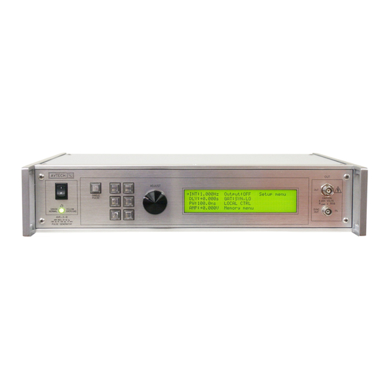
Page 15: Front Panel Controls
FRONT PANEL CONTROLS 1. POWER Switch . This is the main power switch. When turning the instrument on, there is normally a delay of 10 seconds before anything is shown on the main display, as the internal operating system boots up. If the main menu does not appear after 30 seconds, turn off the instrument and leave it off for at least 60 seconds before applying power again. - Page 16 5. LIQUID CRYSTAL DISPLAY (LCD) . This LCD is used in conjunction with the keypad to change the instrument settings. Normally, the main menu is displayed, which lists the key adjustable parameters and their current values. The “Programming Manual for -B Instruments” describes the menus and submenus in detail.
-
Page 17: Rear Panel Controls
REAR PANEL CONTROLS GATE TRIG RS-232 GPIB Note: some connectors may be in different positions than shown above, depending on the exact combination of options ordered. 1. AC POWER INPUT . An IEC-320 C14 three-pronged recessed male socket is provided on the back panel for AC power connection to the instrument. One end of the detachable power cord that is supplied with the instrument plugs into this socket. - Page 18 6. GPIB Connector . A standard GPIB cable can be attached to this connector to allow the instrument to be computer-controlled. See the “Programming Manual for -B Instruments” for more details on GPIB control. 7. RS-232 Connector. A standard serial cable with a 25-pin male connector can be attached to this connector to allow the instrument to be computer-controlled.
-
Page 19: General Information
GENERAL INFORMATION BASIC PULSE CONTROL This instrument can generate two types of waveforms, designated Channel 1 and Channel 2, on the main output. These two channels share a common output connector, and only one is active at a time. The general characteristics of the two channels are as follows: ... - Page 20 100 ns, FIXED SYNC OUT (generated by the 3V, FIXED internal oscillator) DELAY > 0 PULSE WIDTH AMPLITUDE, VARIABLE MAIN OUTPUT OFFSET, VARIABLE Figure A If the delay is negative, the order of the SYNC and OUT pulses is reversed: 100 ns, FIXED SYNC OUT (generated by the...
-
Page 21: Trigger Modes
> 50 ns TRIG TTL LEVELS (external input) (0V and 3V-5V) PROPAGATION DELAY (FIXED) 100 ns, FIXED SYNC OUT 3V, FIXED DELAY > 0 PULSE WIDTH AMPLITUDE, VARIABLE MAIN OUTPUT OFFSET, VARIABLE Figure C As before, if the delay is negative, the order of the SYNC and OUT pulses is reversed. The delay, pulse width, and frequency (when in the internal mode), of the OUT pulse can be varied with front panel controls or via the GPIB or RS-232 computer interfaces. -
Page 22: Gating Modes
GATING MODES Triggering can be suppressed by a TTL-level signal on the rear-panel GATE connector. The instrument can be set to stop triggering when this input high or low, using the front- panel gate menu or the appropriate programming commands. When gated, the output will complete the full pulse width if the output is high, and then stop triggering. -
Page 23: Basic Test Arrangement
BASIC TEST ARRANGEMENT The AVR-D2-B should be tested with a sampling oscilloscope with a bandwidth of at least 2 GHz to properly observe the high-speed waveform. A typical test arrangement is shown below: SAMPLING AVTECH OSCILLOSCOPE PULSER BW > 2 GHz... - Page 24 Other circuits, specified in other MIL-PRF-19500 “slash sheets” can also be driven by the AVR-D2-B. The above circuits are only typical examples. Avtech can provide test jigs (designed using proper high-speed construction techniques) to implement your required test circuitry.
-
Page 25: Minimizing Waveform Distortions
MINIMIZING WAVEFORM DISTORTIONS USE 50 OHM TRANSMISSION LINES Connect the load to the pulse generator with 50Ω transmission lines (e.g. RG-58 or RG- 174 cable). If possible, use a 50Ω load. If the actual device under test has a high impedance, consider adding a 50Ω... -
Page 26: Operational Check
Press the CHANGE button. The active channel submenu will appear. c) Rotate the ADJUST knob until “1” is the actice channel. d) Press CHANGE to return to the main menu. 4. To set the AVR-D2-B to trigger from the internal clock at a PRF of 2 kHz:... - Page 27 a) The arrow pointer should be pointing at the frequency menu item. If it is not, press the MOVE button until it is. b) Press the CHANGE button. The frequency submenu will appear. Rotate the ADJUST knob until the frequency is set at 2 kHz. c) The arrow pointer should be pointing at the “Internal”...
- Page 28 It should agree with the displayed value. 10. To set the AVR-D2-B to generate the Channel 2 waveform on the output connector: a) Press the MOVE button until the arrow pointer is pointing at the “Route” menu item.
-
Page 29: Programming Your Pulse Generator
PROGRAMMING YOUR PULSE GENERATOR KEY PROGRAMMING COMMANDS The “Programming Manual for -B Instruments” describes in detail how to connect the pulse generator to your computer, and the programming commands themselves. A large number of commands are available; however, normally you will only need a few of these. - Page 30 [SOURce]: :PULSe :PERiod <numeric value> :WIDTh <numeric value> | IN :DCYCle <numeric value> :HOLD WIDTh | DCYCle :DELay <numeric value> :GATE :LEVel HIgh | LOw [SOURce]: :VOLTage [:LEVel] [:IMMediate] [:AMPLitude] <numeric value> :LOW <numeric value> :PROTection :TRIPped? [query only] STATUS: :OPERation :[EVENt]? [query only, always returns "0"]...
-
Page 31: Other Information
OTHER INFORMATION APPLICATION NOTES Application notes are available on the Avtech web site, at http://www.avtechpulse.com/ appnote. MANUAL FEEDBACK Please report any errors or omissions in this manual, or suggestions for improvement, to info@avtechpulse.com. Thanks! -
Page 32: Mechanical Information
There are no user-adjustable internal circuits. For repairs other than fuse replacement, please contact Avtech (info@avtechpulse.com) to arrange for the instrument to be returned to the factory for repair. Service is to be performed solely by qualified service personnel. -
Page 33: Maintenance
MAINTENANCE REGULAR MAINTENANCE This instrument does not require any regular maintenance. On occasion, one or more of the four rear-panel fuses may require replacement. All fuses can be accessed from the rear panel. See the “FUSES” section for details. CLEANING If desired, the interior of the instrument may be cleaned using compressed air to dislodge any accumulated dust. -
Page 34: Wiring Diagrams
WIRING DIAGRAMS WIRING OF AC POWER M a ins circuits - ha z ard ou s live . Do not attem pt any repairs on this instrument bey ond the fuse replacement procedures described in the m anual. Contact Av tech if the instrument A3 - BLACK requires serv icing. -
Page 35: Wiring Of High-Voltage Dc Power Supplies
WIRING OF HIGH-VOLTAGE DC POWER SUPPLIES PCB 235B -24V +FIXED +VAR STD: +90V / 0 T O +90V UV SSR SOA: +100V / 0 T O +105V 235B +24V, NO OLO R7 = 5K 3266W R8 = 100 OY +24V, NO OLO R6 = 4.7K R9 =... -
Page 36: Pcb 158R4 - Low Voltage Power Supply
PCB 158R4 - LOW VOLTAGE POWER SUPPLY... -
Page 37: Pcb 235B - High Voltage Dc Power Supply
PCB 235B - HIGH VOLTAGE DC POWER SUPPLY... -
Page 38: Pcb 151D - Range Control
PCB 151D - RANGE CONTROL... -
Page 39: Pcb 217A - Relay Driver
PCB 217A - RELAY DRIVER K E Y S T O N E 6 2 1 B R A C K E T P S 7 1 0 A - 1 A P S 7 1 0 A - 1 A K E Y S T O N E 6 2 1 B R A C K E T 1 . -
Page 40: Pcb 104F - Keypad / Display Board, 1/3
PCB 104F - KEYPAD / DISPLAY BOARD, 1/3 Amp 5 4 9 9 9 1 0 -1 , 1 0 p in strai g h t h ead er LC D-BU TT LC D-BU TT. SCH SD A SD A SC L SC L GN D... -
Page 41: Pcb 104F - Keypad / Display Board, 2/3
PCB 104F - KEYPAD / DISPLAY BOARD, 2/3 U4 A VC C C1 0 VC C BU T1 VC C 2 . 2 u F C1 5 C1 3 0 . 1 u F 0 . 1 u F 0 . 1 u F 0 . -
Page 42: Pcb 104F - Keypad / Display Board, 3/3
PCB 104F - KEYPAD / DISPLAY BOARD, 3/3 VC C VC C 0 . 1 u F 2 . 2 u F GN D VC C VC C VC C SD A SD A SC L SC L GN D PA D3 PA D4 PC F8 5 7 4 AN (MU ST HA VE "A"... -
Page 43: Main Wiring
MAIN WIRING PCB151D CHA NG ES REQ UIRED O N PCB 151D: A RLY (+15V) 1. REMO VE R9, R11 +24V FOR BN -30V 2. INST A LL R 10 = ZERO +24V, N O OLO HV, NO OLO -15V, PGB-N 3. -
Page 44: Performance Check Sheet
PERFORMANCE CHECK SHEET...
Need help?
Do you have a question about the AVR-D2-B and is the answer not in the manual?
Questions and answers