Advertisement
Quick Links
Thomas
XTSR52 Installation and Maintenance
®
(Page 1 of 13)
Type XTSR52
Sizes 494-5258
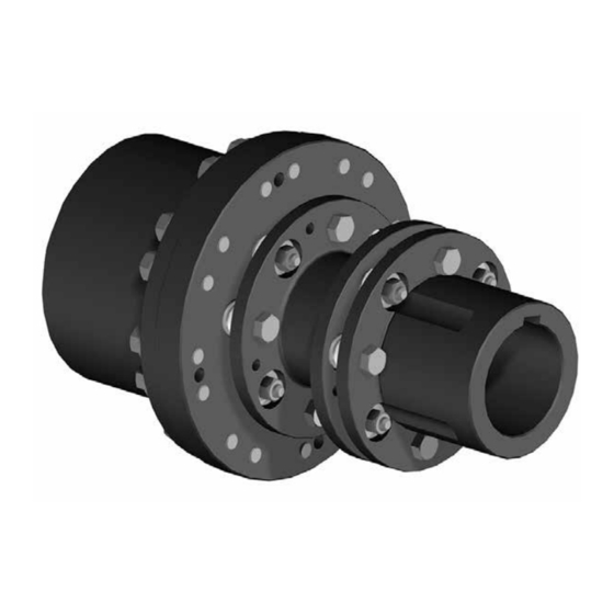
Figure 1 – Thomas XTSR52 Coupling without Adapter and with Adapter and Large Hub
1. General Information
1.1 Rexnord Thomas Couplings are designed to provide a mechanical connection between the rotating shafts of mechanical equipment, using flexible
discs to accommodate inherent misalignment while transmitting the power and torque between the connected shafts.
1.2 These instructions are intended to help you to install and maintain your Rexnord Thomas coupling. Please read these instructions prior to
installing the coupling, and prior to maintenance of the coupling and connected equipment. Keep these instructions near the coupling installation
and available for review by maintenance personnel. For special engineered couplings, Rexnord may provide an engineering drawing containing
installation instructions that take precedence over this document.
1.3 Rexnord owns the copyright of this material. These Installation and Maintenance instructions may not be reproduced in whole or in part for
competitive purposes.
1.4 Symbol descriptions:
Danger of injury to persons.
Damages on the machine possible.
Pointing to important items.
Hints concerning explosion protection.
Rexnord
5555 S. Moorland Rd., New Berlin, WI 53151-7953
Phone: 262-796-4060 Fax: 262-796-4064 www.rexnord.com
Sizes 494-5258
CP3-002
September 2017
Supersedes 09-2016
Advertisement

Related Manuals for Rexnord Thomas XTSR52


Summary of Contents for Rexnord Thomas XTSR52
- Page 1 For special engineered couplings, Rexnord may provide an engineering drawing containing installation instructions that take precedence over this document. 1.3 Rexnord owns the copyright of this material. These Installation and Maintenance instructions may not be reproduced in whole or in part for competitive purposes.
- Page 2 2.15 The coupling may only be used in accordance with the technical data provided in the Thomas disc coupling catalog. Customer modifications and alterations to the coupling are not permissible. 2.16 All spare parts for service or replacement must originate from or be approved by Rexnord. CP3-002 Rexnord 5555 S.
- Page 3 (Page 3 of 13) Sizes 494-5258 Cap Screws Figure 2 – Rexnord Thomas XTSR52 Coupling Components Note: Coupling component numbers above correspond to the component numbers in the column headers of Tables 1 and 2. Figure 3 – Disc Pack Hardware Kit Consisting of above.
- Page 4 ® (Page 4 of 13) Sizes 494-5258 Table 1 – Rexnord Thomas XTSR52 Coupling Component Part Numbers Note: the circled numbers identified in the column headers below, correspond to the coupling component numbers in Figure 2. LH Hub + Cap ...
- Page 5 (Page 5 of 13) Sizes 494-5258 Table 2 – Rexnord Thomas XTSR52 Coupling Component Part Numbers Note: the circled numbers identified in the column headers below, correspond to the coupling component numbers in Figures 2 and 3. Hardware Kit Bolts, Locknuts, and Overload Disc Pack ...
-
Page 6: Hub Mounting
4.4 If used; assemble and tighten the set screw(s) using a calibrated torque wrench to the values shown in Table 3. CP3-002 Rexnord 5555 S. Moorland Rd., New Berlin, WI 53151-7953 September 2017 Phone: 262-796-4060 Fax: 262-796-4064 www.rexnord.com Supersedes 09-2016... - Page 7 6.10 With the hub expanded, install it quickly on the shaft to the “zero” set point. Continue to advance the hub up the taper to the desired axial position, as defined by Rexnord’s customer. Use the indicator as a guide only. A pre-set axial stop device can be helpful.
-
Page 8: Shaft Alignment
(X-Y) taken at opposite ends of the hub flange, and spacer flange as shown in Figure 10. Figure 8 Figure 9 Figure 10 CP3-002 Rexnord 5555 S. Moorland Rd., New Berlin, WI 53151-7953 September 2017 Phone: 262-796-4060 Fax: 262-796-4064 www.rexnord.com Supersedes 09-2016... - Page 9 Note: 1. Refer to Rexnord Bulletin 538-214 Coupling Alignment Fundamentals for more details regarding alignment methods and procedures. a. The Angular Misalignment value is the maximum difference between the measurements X and Y taken at opposite ends of the hub flanges, as shown in Figure 10.
-
Page 10: Final Assembly
8.12 Proceed to the other end of the coupling. Remove the support bolts, if used, and continue to support the center member. Repeat steps 8.5 through 8.10 to install the second disc pack. CP3-002 Rexnord 5555 S. Moorland Rd., New Berlin, WI 53151-7953 September 2017 Phone: 262-796-4060 Fax: 262-796-4064 www.rexnord.com Supersedes 09-2016... - Page 11 8.19 Continue spacer installation by following instructions 8.6 through 8.12. “C” Length Figure 12 - Short “C” Length Scalloped Center Member CP3-002 Rexnord 5555 S. Moorland Rd., New Berlin, WI 53151-7953 September 2017 Phone: 262-796-4060 Fax: 262-796-4064 www.rexnord.com Supersedes 09-2016...
- Page 12 Note: Center member subassemblies with adapters have their locknuts factory tightened. On center member subassemblies where the spacer length is short and wrench access is limited, special wrenches are used to tighten the locknuts. Consult Rexnord for assistance in obtaining special wrenches.
- Page 13 2. Bolts should be held from rotating while the locknuts are tightened to the values shown. Do not tighten the fastener by rotating the bolt head. Figure 13 Figure 14 CP3-002 Rexnord 5555 S. Moorland Rd., New Berlin, WI 53151-7953 September 2017 Phone: 262-796-4060 Fax: 262-796-4064 www.rexnord.com Supersedes 09-2016...
Need help?
Do you have a question about the Thomas XTSR52 and is the answer not in the manual?
Questions and answers