Table of Contents
Advertisement
406MHz SATELLITE EMERGENCY POSITION INDICATING RADIO BEACON
406MHz SATELLITE EMERGENCY POSITION INDICATING RADIO BEACON
Actual Producer : MITSUBISHI ELECTRIC TOKKI SYSTEMS CORPORATION
Actual Producer : MITSUBISHI ELECTRIC TOKKI SYSTEMS CORPORATION
( 406MHz Satellite EPIRB
406MHz Satellite EPIRB )
OPERATION
OPERATION
JQE-103
JQE-103
MANUAL
MANUAL
Advertisement
Table of Contents

Related Manuals for JRC JQE-103


Summary of Contents for JRC JQE-103
- Page 1 JQE-103 JQE-103 406MHz SATELLITE EMERGENCY POSITION INDICATING RADIO BEACON 406MHz SATELLITE EMERGENCY POSITION INDICATING RADIO BEACON ( 406MHz Satellite EPIRB 406MHz Satellite EPIRB ) OPERATION OPERATION MANUAL MANUAL Actual Producer : MITSUBISHI ELECTRIC TOKKI SYSTEMS CORPORATION Actual Producer : MITSUBISHI ELECTRIC TOKKI SYSTEMS CORPORATION...
-
Page 3: Attentions Before Using
PREFACE Thank you for purchase of the JQE-103 406MHz EMERGENCY POSITION INDICATING RADIO BEACON ( Satellite EPIRB). It is designed for use by mariners in distress to initiate the transmission of an emergency distress locating signal to the Satellites. •... -
Page 4: About Warning Labels And Identification Plates
ABOUT WARNING LABELS AND IDENTIFICATION PLATES <Attached to Satellite EPIRB main body> <Attached to Automatic Release Bracket> (7)... -
Page 5: Before Operation
BEFORE OPERATION About safety symbols This manual and the terminal are indicated the following safety symbols for your correct operation to prevent your and somebody’s injury or damage to the product and assets. The symbols and descriptions are as follows. You should understand well them before reading this manual and operating the terminal. -
Page 6: Cautions During Operation
CAUTIONS DURING OPERATION WARNING <Use of Main body> If the false distress alert is transmitted, take the following instructions immediately. (1) Stop the transmission immediately. (2) Report the following information to the Maritime Safety Agency. (a) Ship’s Name, Type and Flag (b) MMSI (Maritime Mobile Service Identification) of Satellite EPIRB (c) Position and Time at the false transmission (d) Cause of the false transmission... - Page 7 If the ship’s name and ID indicated on the label of the Satellite EPIRB main unit is wrong, ask the purchasing dealer, JRC agent or one of the JRC branches to change it with correct ship’s name and When the ship meets disaster, a large trouble will be given to the search rescue organization when ship information on Satellite EPIRB is wrong.
- Page 8 It disturbs the automatic release at emergency. <Maintenance: Main body> Ask the maintenance of Satellite EPIRB to the purchasing dealer, JRC agent or one of the JRC branches. This device is used in urgent accident, and equipment should ensure it.
- Page 9 Send used batteries to the purchasing dealer, JRC agent or one of the JRC branches. Do not discard used batteries. Send used batteries to the purchasing dealer, JRC agent or one of the JRC branches, to avoid causing environmental problem by throwing them away.
- Page 10 <Others> Ask the service to purchasing dealer, JRC agent or one of the JRC branches if the battery, hydraulic pressure sensor or stopper pin is replaced or the abnormal status is recognized in the Satellite EPIRB.
-
Page 11: Appearance
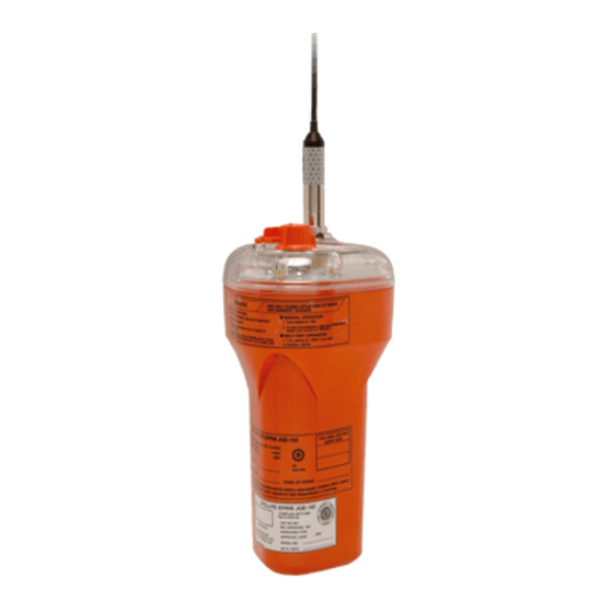
APPEARANCE Satellite EPIRB Fig.1 Satellite EPIRB Automatic release bracket Fig.2 Automatic release bracket... -
Page 12: Glossary
GLOSSARY EPIRB Emergency Position Indicating Radio Beacon GMDSS Global Maritime Distress and Safety System Cospas-Sarsat International satellite system for maritime search and rescue LEOSAR Low-Earth-Obit Satellite System for Search and Rescue MMSI Maritime Mobile Service Identity Search And Rescue... -
Page 13: Operation At Emergency (Manual Activation)
OPERATION AT EMERGENCY (MANUAL ACTIVATION) Turn the stopper to arrow mark direction breaking the stopper pin. Turn ON the selector switch. Then, the indication lamp flashes and distress signal is transmitted for over 48 hours. After setting, turn the stopper back to original position to keep switch ON. Stopper pin Stopper Selector switch... -
Page 15: Table Of Contents
CONTENTS PREFACE ........................................i ATTENTIONS BEFORE USING ................................. i ABOUT WARNING LABELS AND IDENTIFICATION PLATES ..................ii BEFORE OPERATION ..................................iii CAUTIONS DURING OPERATION ..............................iv APPEARANCE ......................................ix GLOSSARY ....................................... x OPERATION AT EMERGENCY (MANUAL ACTIVATION) ....................xi CHAPTER 1. INTRODUCTION .......................... - Page 16 4-7-2 How to discard the Satellite EPIRB ............................. 4-7 4-7-3 Necessary procedure for Satellite EPIRB installed in the vessel to be resold ..............4-9 CHAPTER 5. SPECIFICATIONS ........................... 5-1 5-1 Electrical specifications ................................5-1 CHAPTER 6. JRC SERVICE NETWORK ......................6-1...
-
Page 17: Chapter 1. Introduction
CHAPTER 1. INTRODUCTION 1.1 System Outline Satellite EPIRB is a beacon installed onto the ship under GMDSS rule. Should the ship sink, the Satellite EPIRB will automatically float on the water, emit 406.028 MHz and 121. 5 MHz distress beacon for over 48 hours. The 406.028 MHz beacon is received by LEOSAR of the COSPAS/SARSAT system, and distress position is measured by Doppler effect between moving speed of the satellite and rotation of the earth. -
Page 18: Feature Of Satellite Epirb
1-2 Feature of Satellite EPIRB The Satellite EPIRB emergency position indicating radio beacon has the following features. ▪ Emitting 2 types of distress signals: 406.028 MHz and 121.5 MHz ▪ The Satellite EPIRB main unit attached to the automatic release bracket is automatically released within water depth 4 meters and sends two types of distress signals. -
Page 19: Configration
1-3 Configration 1-3-1 Components Table 1-3-1 Components list Name Dimension, etc. Weight Q’ty JQE-103 Satellite EPIRB 120(W) x 529(H) x 116(D) mm Approx. 1.3 kg (including antenna) NYH-12 Automatic 175(W) x 585(H) x 175(D) mm Approx. 2.9 kg release bracket Stainless bolt with hexagonal hole 4 each. -
Page 20: Satellite Epirb Main Unit
1-3-2 Satellite EPIRB main unit Antenna Indicator lamp Stopper pin Orange LED (Lights while power ON) Yellow LED (Lights while TEST) Stopper Red LED (Lights while transmitting 406.028MHz) Selector switch Antenna Selector switch EPIRB main unit Fig.1-3-2 EPIRB main unit... -
Page 21: Automatic Release Bracket
1-3-3 Automatic release bracket Band Fig.1-3-3 Automatic release bracket... -
Page 23: Chapter 2. Installation
CHAPTER 2. INSTALLATION This unit must be installed by the dealer or service person. Therefore, this chapter provides only general information related to the system. For detailed information about the system, please refer to the Installation Manual. NOTE Refer the Installation manual for the detail of installation. WARNING The selector switch is set to “READY”... -
Page 24: Outline Of Installation
WARNING This unit may be damaged due to vibration. Do not absolutely install this unit in an extremely vibrating place such as a handrail. This unit must not be installed in a place where a strong magnetic field is generated. The Satellite EPIRB may activate by the magnetic force. -
Page 25: Chapter 3. Operation
CHAPTER 3. OPERATION 3-1 Selector switch The selector switch of this unit has following three positions. (1) READY Used to automatic activation. Distress signals are emitted immediately when the conductive switch senses water after the Satellite EPIRB main unit is released from the automatic release bracket. That is, the Satellite EPIRB main unit must float on the water surface to be able to emit distress signals. -
Page 26: Power Off
Be sure to return the stopper to the original position after the selector switch was set. Stopper Stopper pin Selector switch Fig.3-1b Reset of the Stopper 3-2 Power OFF Confirm that the selector switch is set to “READY” (If not, set it to “READY”), and take the Satellite EPIRB out of water. -
Page 27: Manual Activation
3-3 Manual activation WARNING Do not set the selector switch to “ON “except the case of manual activation in the emergency. Distress signals are emitted when turning the selector switch “ON”. If the selector switch is set to “ON”, the Satellite EPIRB is activated, and it sends distress signals 50 seconds later regardless of its status. -
Page 28: Automatic Activation
CAUTION Open slowly the cover of release bracket. If you open faster, EPIRB main unit may deviate from release bracket and fall down. NOTE Manual activation is not possible unless breaking the stopper pin. Therefore, broken stopper pin is the evidence that the EPIRB had been once activated manually. In that case, replacing of the battery is required together with stopper pin. -
Page 29: Lanyard
3-5 Lanyard The lanyard is used to tow the Satellite EPIRB by connecting with a float or survival boat. WARNING Never connect the lanyard to the automatic release bracket or ship body. It disturbs the automatic release at emergency. Fig.3-5 The lanyard... -
Page 30: Test
Contact Check the The battery is LED blink for 4 sec. in 0.5 purchased battery somewhat consumed. sec. interval. dealer or JRC voltage *1 Yellow LED and orange Contact The battery is LED blink for 4 sec. in purchased exhausted. - Page 31 48 hours. If an error is detected by this test or the effective periods of the battery and hydraulic pressure sensor expired, contact the purchasing dealer, JRC agent or one of the JRC branches. WARNING The battery and hydraulic pressure sensor which expired effective periods must not absolutely be used.
-
Page 32: Mounting Of The Satellite Epirb Main Unit Into Automatic Release Bracket
3-7 Mounting of the Satellite EPIRB main unit into automatic release bracket Mount the Satellite EPIRB main unit into the automatic release bracket, in accordance with the following procedure. (1) Set the band on the mount base of the automatic release bracket. Fig.3-7a Mounting band to automatic release bracket (1) Band Plate... - Page 33 (2) Then, put the Satellite EPIRB main unit on the mount base. 1) Fit the bottom of the Satellite EPIRB main unit on the bottom stopper of the mount base of automatic release bracket. Mount base of the Automatic release bracket Bottom of the EPIRB main unit Bottom stopper...
- Page 34 3) Insert the top of antenna on cushion B Antenna Insert this part Cushion B Fig.3-7e Mounting antenna to cushion B (3) Put the mount cover on the mount base from bottom side, and fasten the belt over the mount cover to do not bend, and fasten with catch clip.
- Page 35 (4) Open the hatch, and confirm following things. Be sure to shut the hatch after confirmed those. ▪ Selector switch is set to “READY”. ▪ Stopper is set tightly. ▪ Stopper pin is not broken. Hatch Fig.3-7g Confirmation after mounting Antenna Stopper pin Stopper...
-
Page 36: Removal Of Satellite Epirb Main Unit From Automatic Release Bracket
WARNING Mount the Satellite EPIRB main unit on the automatic release bracket properly. Improper mounting causes the Satellite EPIRB not to be automatically released from the bracket in an emergency. 3-8 Removal of Satellite EPIRB main unit from automatic release bracket Remove the Satellite EPIRB main unit from the automatic release bracket by reverse order of procedure in CHAPTER 3-7, (2) to (4). -
Page 37: Chapter 4. Implementation / Maintenance / Check / Cleaning
CHAPTER 4. IMPLEMENTATION / MAINTENANCE / CHECK / CLEANING 4-1 Implementation The selector switch must be set to the “READY” position while sailing. WARNING The selector switch must be set to the “READY” position while sailing. Antenna Stopper pin Stopper Selector switch Fig.4-1 Confirmation of Selector switch position If the ship sank as the selector switch is set to the READY position, the automatic release bracket releases the... -
Page 38: Maintenance
(6) Isn’t there any deformation (6) Contact the purchased dealer, JRC agent or one of the JRC or damage on the main branches if there is any deformation or damage on those. -
Page 39: Periodical Cleaning Of Conductive Switch Terminal
4-3 Periodical cleaning of conductive switch terminal (1) Importance of periodical cleaning This Satellite EPIRB transmits distress signal after detecting water when it is activated by automatic release. Although the Satellite EPIRB is stored in a case (automatic release bracket), small dust may invades into the case and adhere on the conductive switch terminal as the automatic release bracket is not water-tight structure. - Page 40 CAUTION Do not wipe the both of conductive switch terminals in the same time. It might cause the false transmission of distress signal due to the sensor detects the water and activated. Do not use salt water to wipe the Satellite EPIRB. Using salt water may cause false transmission of the distress signal by adhering salt on the conductive switch terminals.
-
Page 41: Test
4-4 Test This unit has the following test functions. Please refer section 3-6 “Test” for the details. CAUTION In this test, permitted distress signal for the test purpose is transmitted only by one burst. Do not execute the test repeatedly in a short time frame. Execute the test in 00 - 05 minutes of each o’clock for the reduction of processing capacity in the satellite. -
Page 42: Cleaning Of Satellite Epirb Main Unit
Satellite EPIRB directly or indirectly. (5) Contact the purchasing dealer, JRC agent or one of the JRC branches immediately for repair when you found a crack on the body of Satellite EPIRB. -
Page 43: After Service
Satellite EPIRB. (3) Contact the purchasing dealer, JRC agent or one of the JRC branches and notify the name of the vessel and serial number of the Satellite EPIRB to be abandoned. - Page 44 Send used batteries to the purchasing dealer, JRC agent or one of the JRC branches. Do not discard used batteries. Send used batteries to the purchasing dealer, JRC agent or one of the JRC branches, to avoid causing environmental problem by throwing them away.
-
Page 45: Necessary Procedure For Satellite Epirb Installed In The Vessel To Be Resold
In case of that Japanese flag vessel is resold to Japanese client and new owner succeeds in the radio station license. (Contact t the purchasing dealer, JRC agent or one of the JRC branches, and ask them to take necessary procedure and work as mentioned below.) To avoid accidental emission, make sure that the switch position of Satellite EPIRB is set to “READY”,... - Page 46 MMSI of inner main body, and installation to the new ship) to purchasing dealer, JRC agent or one of the JRC branches (refer to CHAPTER 4-7, After Service) If these procedures and works are not executed, false transmission or wrong ID code signal might be emitted in distress, and it causes serious confusion for search and rescue operation.
-
Page 47: Chapter 5. Specifications
CHAPTER 5. SPECIFICATIONS 5-1 Electrical specifications A) General specifications A-(1) Main unit When the Satellite EPIRB is left in the water at 10m depth for five minutes, no Water-proof abnormality arises to Satellite EPIRB. Operation temperature -20°C to +55°C Set the Satellite EPIRB on a vibration tester, and apply the following vibration Vibration to the direction of up and down, right and left, and back and forth for fifteen minutes each. - Page 48 B) Electrical specifications B-(1) 406 MHz Long-time stability 406.028 MHz (within +2 kHz, -5 kHz) Short term : Less than 2 x 10 /100 ms Medium term Frequency stability Mean slope : Less than ±1 x 10 /min. Residual frequency variation : Less than 3 x 10 Output power Less than 5 W ±2 dB Intensity of unwanted radiation during modification is shown below.
- Page 49 B-(3) Homing signal Transmitting frequency 121.5 MHz ± 6.075 kHz Peak radiation power 50 mW ±3 dB Modulation Modulation frequency 300 Hz to 1600 Hz Modulation repetition cycle 2 Hz to 4 Hz B-4) Battery Model Model P-35 Type Lithium Manganese dioxide pack Composition Serial 3 cells Voltage...
-
Page 51: Chapter 6. Jrc Service Network
CHAPTER 6. JRC SERVICE NETWORK Please contact the dealer from which you purchased the device or our marketing offices that is nearest to you for any question as to the after-sales service (See back cover). Please refer to the back of the book for more information. - Page 54 For further information,contact: http://www.jrc.co.jp Marine Service Department Telephone : +81-3-3492-1305 Facsimile : +81-3-3779-1420 e-mail : tmsc@jrc.co.jp SEATTLE Branch Telephone : +1-206-654-5644 Facsimile : +1-206-654-7030 Not use the asbestos e-mail : marineservice@jrcamerica.com http://www.alphatronmarine.com Rotterdam (Head office) Alphatron Marine B.V. Telephone :...
Need help?
Do you have a question about the JQE-103 and is the answer not in the manual?
Questions and answers