
Related Manuals for JRC JCX-161


Summary of Contents for JRC JCX-161
- Page 1 JCX - 161 Bridge Navigational Bridge Navigational Watch Alarm System Watch Alarm System INSTRUCTION INSTRUCTION MANUAL MANUAL...
- Page 3 Preface Thank you for purchasing the JRC bridge navigational watch alarm system, JCX-161. This system monitors the activities of the navigational officer on the bridge and detects any abnormal conditions in the officer that may lead to a marine accident. If the officer cannot fulfill his duties for any reason, the system alerts the captain or other qualified personnel.
-
Page 4: Before Use
Before use Warning Symbols The warning labels in the instruction manual and on the system use various symbols to ensure that the system is used correctly and prevent personal injury or equipment damage. The symbols and their meanings are shown below. - Page 5 Do not attempt to exchange the fuse by yourself. Exchange by anyone other than qualified maintenance personnel may result in a fire, electrical shock, or equipment malfunction. For an exchange of the fuse, contact the JRC sales department, a nearby branch office, business office, or any JRC agent.
- Page 6 If a strange smell, smoke, or unusual heat is emitted from any equipment, shut off the power immediately and disconnect the power cable. Then contact the JRC sales department, a nearby branch office, business office, or any JRC agent. Continued use of the equipment may result in a fire or electrical shock.
- Page 7 The caution on use CAUTION When the system is exposed to fresh water or seawater, wipe it immediately. Otherwise, a failure or malfunction may occur. When cleaning the system surface, do not use any organic solvent such as thinner or benzine ; these solvents damage the surface coating. To clean the surface, remove dust and debris then wipe it with a clean dry cloth.
- Page 8 The caution on use CAUTION Do not bring the system into a warm room while it is cool. Dew condensation may occur inside, leading to a machine failure. Before turning on the power switch again, make sure that the screen of the LCD display unit goes out.
-
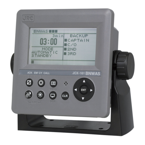
Page 9: Jcx-161 Bridge Navigational Watch Alarm System External Appearance
Equipment Appearance JCX-161 Bridge Navigational Watch Alarm System External Appearance... -
Page 10: Table Of Contents
Preface ............................ⅰ Before use ............................ⅱ The cautions on use ........................ⅲ JCX-161 Bridge Navigational Watch Alarm System External Appearance ........vii Chapter 1 General Outline of Equipment ................... 1 1.1 Functions ............................ 1 1.1.1 Purpose of the system ......................1 1.1.2 Operation modes........................ - Page 11 Contents 2.7.1 Names and functions of system components ..............30 Chapter 3 Operation ........................... 33 3.1 WATCH ALARM operation ......................34 3.1.1 Operation sequence of displays and alarms ..............34 3.1.2 Operation of each unit for every alarm ................35 3.2 Operation mode change ......................
- Page 12 Contents 4.5 Periodic replacement part ......................62 Chapter 5 Usage Environment ......................63 Chapter 6 After Service ........................65 Chapter 7 Disposal ..........................67 7.1 Disposal of the system ......................67 7.2 Chinese version of RoHS ......................67 Chapter 8 Specification ........................69 8.1 Control unit (NCK-175) ......................
-
Page 13: Chapter 1 General Outline Of Equipment
Chapter 1 General Outline of Equipment Chapter 1 General Outline of Equipment 1.1 Functions The system is a Bridge Navigational Watch Alarm System (BNWAS) consisting of a control unit, a display unit, a buzzer units, and a reset devises. It is designed to prepare for any contingency in which a duty officer is disabled to fulfill his duties due to a nap, health problem, or other reason. -
Page 14: Operation Sequence Of Displays And Alarms
Chapter 1 General Outline of Equipment 1.1.3 Operation sequence of displays and alarms Depending on the operation mode, the unit is activated and the dormant period countdown starts. When the countdown ends, the following displays and alarms are triggered. 1) Visual Indication At the end of this dormant period, the alarm system initiates a visual indication on the bridge. -
Page 15: Features
Chapter 1 General Outline of Equipment 1.2 Features 1.2.1 Versatile functions with standard configuration 1) BNWAS function When dormant period are measured, and the confirmation is not done, warning is output with the visible display and the alarms according to the sequence of 1.1.3. 2)... -
Page 16: Configuration
Chapter 1 General Outline of Equipment 1.3 Configuration Component list of bridge navigational watch alarm system (BNWAS) Item Model Q'ty Mass (kg) Remarks (exp.) Standard configuration Control unit NCK-175 Attached operation card (7ZPNA4319) ,power LCD display unit NWZ-4650 cable(CFQ-5766B),data cable(CFQ-5951B) , Fuse (2A, 1A, 1 piece each) Buzzer unit NVS-785... -
Page 17: Outline Dimensions
Chapter 1 General Outline of Equipment 1.4 Outline dimensions 1.4.1 Control unit (NCK-175) COLOR : N4 SEMI-GLOSS MASS : APPROX. 4.5kg IP SPEC : IP22 UNIT : mm CATEGORY : Protected Control unit (NCK-175) Outline Dimensions... -
Page 18: Lcd Display Unit (Nwz-4650)
Chapter 1 General Outline of Equipment 1.4.2 LCD display unit (NWZ-4650) COLOR : N4 SEMI-GLOSS MASS : APPROX. 0.6kg IP SPEC : IP22 UNIT : mm CATEGORY : Protected LCD display unit (NWZ-4650) Outline Dimensions (attached self-supported stand) -
Page 19: Buzzer Unit (Nvs-785)
Chapter 1 General Outline of Equipment 1.4.3 Buzzer unit (NVS-785) COLOR : N4 SEMI-GLOSS MASS : APPROX. 0.2 kg IP SPEC : IP22 UNIT : mm CATEGORY : Protected Buzzer unit (NVS-785) Outline Dimensions... -
Page 20: Reset Button Unit (Ncj-895)
Chapter 1 General Outline of Equipment 1.4.4 Reset button unit (NCJ-895) COLOR : N4 SEMI-GLOSS MASS : APPROX. 0.2 kg IP SPEC : IP22 UNIT : mm CATEGORY : Protected Reset button unit (NCJ-895) Outline Dimensions... -
Page 21: Motion Sensor (Nyg-5) (Option)
Chapter 1 General Outline of Equipment 1.4.5 Motion sensor (NYG-5) (Option) COLOR : N4 SEMI-GLOSS MASS : APPROX. 0.4 kg IP SPEC : IP22 UNIT : mm CATEGORY : Protected Motion sensor (NYG-5) Outline Dimensions... -
Page 22: Led Warning Lamp Unit (Ncd-2257) (Option)
Chapter 1 General Outline of Equipment 1.4.6 LED Warning lamp unit (NCD-2257) (Option) COLOR : N4 SEMI-GLOSS MASS : APPROX. 0.2 kg IP SPEC : IP22 UNIT : mm CATEGORY : Protected LED warning lamp unit (NCD-2257) Outline Dimensions... -
Page 23: Reset Button Unit (Waterproof) (Ncj-896) (Option)
Chapter 1 General Outline of Equipment 1.4.7 Reset button unit (Waterproof) (NCJ-896) (Option) COLOR : N4 SEMI-GLOSS MASS : APPROX. 0.5 kg IP SPEC : IP56 UNIT : mm CATEGORY : Exposed Reset button unit (Waterproof) (NCJ-896) Outline Dimensions... -
Page 24: System Diagram
Chapter 1 General Outline of Equipment 1.5 System diagram... -
Page 25: Chapter 2 Names And Functions Of System Components
Chapter 2 Names and Functions of System Components Chapter 2 Names and Functions of System Components 2.1 Power switch and how to turn it on The power source is distributed from the control unit (NCK-175) to each unit of the system, and there is no power source switch at any devices. - Page 26 Chapter 2 Names and Functions of System Components 2) How to turn on the power. In order to switch on the power, turn the AC switch and DC switch on. DC ON AC ON DC OFF AC OFF...
- Page 27 Chapter 2 Names and Functions of System Components 3) How to turn off the power DC ON AC ON DC OFF AC OFF In order to turn off the power, turn the AC switch and DC switch off.
-
Page 28: Lcd Display Unit (Nwz-4650)
Chapter 2 Names and Functions of System Components 2.2 LCD Display unit (NWZ-4650) The LCD display unit (NWZ-4650) can be operated variously with 9 buttons under the Liquid Crystal Display (LCD). 2.2.1 Mark and function of button Mark of button Function of button Contrast is adjusted. - Page 29 Chapter 2 Names and Functions of System Components Mark of button Function of button Selections or settings are decided. Sound of audible alarm units occurring system abnormality and bridge alarm is deactivated. An emergency call is generated. Sound of all audible alarm units is activated.
-
Page 30: Display And Function Of Screen
Chapter 2 Names and Functions of System Components 2.2.2 Display and function of screen ① ② ④ ③ ⑥ ⑤ Display Function Countdown The remaining dormant period is displayed with the bar graph. The remaining dormant period is displayed with numerical time value Countdown (min/s). -
Page 31: Display Of Each Alarm Stage
Chapter 2 Names and Functions of System Components 2.2.3 Display of each alarm stage The display of the LCD screen is changes with the each alarm stage. Also, the back light of the LCD lights up alternately with ORANGE and WHITE. 1) Display at visible indication ②... - Page 32 Chapter 2 Names and Functions of System Components 3) Display at Second Stage Remote audible alarm ② ① "2ND STAGE REMOTE ALARM" for meaning the 2nd Stage Remote audible alarm is displayed in ①, and remaining time is displayed at ② until the next alarm stage. 4) Display at Third Stage Remote audible alarm ①...
-
Page 33: Buzzer Unit (Nvs-785)
Chapter 2 Names and Functions of System Components 2.3 Buzzer unit (NVS-785) This outputs the 1st Stage Bridge audible alarm, the 2nd stage remote audible alarm and 3rd stage remote audible alarm from the control unit (NCK-175) by buzzer operation and LED illumination. -
Page 34: Reset Button Unit (Ncj-895)
Chapter 2 Names and Functions of System Components 2.4 Reset button unit (NCJ-895) The reset botton unit NCJ-895 has the following five functions. 1) Report an end of the dormant period as a visual indication devise. 2) Sound 1st stage bridge audible alarm. 3) Reset dormant periods as a reset device. - Page 35 Chapter 2 Names and Functions of System Components 1) Visual indication function of reset button unit 1st stage 2nd stage 3rd stage Normal Visual Bridge remote remote Bridge EMERGENCY state Indication audible audible audible Alarm EMERGENCY CALL alarm alarm alarm CALL Sound/ Illuminated...
- Page 36 Chapter 2 Names and Functions of System Components 200ms 200ms 200ms 200ms 200ms 200ms 200ms Turn on Turn on Turn on Turn on Turn on Turn on Turn on 200ms 200ms 200ms 200ms 200ms 200ms 1(sec) 1(sec)
-
Page 37: Motion Sensor (Nyg-5) (Option Device)
Chapter 2 Names and Functions of System Components 2.5 Motion sensor (NYG-5) (Option device) The motion sensor uses the pyroelectric type infrared sensor and detects human motions by sensing the variation of infrared radiated from the human body, and resets the dormant period automatically. - Page 38 Chapter 2 Names and Functions of System Components 2) Specification of a motion sensor As below, the human body is detected in the range of vertical angle 81° to horizontal angle 100°, and an automatic reset is made when a person crosses (moves in) the detection zone. This sensor must be set 2 to 4 meters away from the place where the crews perform regular works.
- Page 39 Chapter 2 Names and Functions of System Components Vertical direction 2.31 40.4° 1.73 1.15 0.58 0.58 1.15 1.73 40.4° 2.31 3m The motion sensor reacts to infrared ray radiated from a human body. Therefore, it does not react to curtains but should not be located near a swaying incandescent lamp. In addition, it must be noted that the sensor may react to small animals such as birds, dogs and cats because any living organism radiates infrared ray.
-
Page 40: Led Warning Lamp Unit (Ncd-2257) (Option Device)
Chapter 2 Names and Functions of System Components 2.6 LED Warning lamp unit (NCD-2257) (Option device) NCD-2257 is a lamp unit that reports a visual indication. It remains off in normal state and blinks at the visual indication and alarm state. 2.6.1 Names and functions of system components ①... - Page 41 Chapter 2 Names and Functions of System Components The blink patterns change with alarm stages. Blink pattern at visual indication 1 s turn on - 1 s turn off Turn on Turn off 1(sec) 1(sec) Blink pattern at first stage bridge audible alarm 1 time blink/1 s -...
-
Page 42: Reset Button Unit (Waterproof) (Ncj-896)
Chapter 2 Names and Functions of System Components 2.7 Reset button unit (Waterproof) (NCJ-896) The reset button unit (waterproof) NCJ-896 has the following four functions. 1) Report an end of the dormant period as a visual indication devise. 2) Sound 1st stage bridge audible alarm. 3) Reset dormant periods as a reset device. - Page 43 Chapter 2 Names and Functions of System Components Name Function Buzzer This is sounded at the first stage bridge audible alarm or the various (Audible alarm ① alarms. device) This resets the dormant period, and stops the visual indication and the Reset button audible alarm.
- Page 44 Chapter 2 Names and Functions of System Components 1) The visible display function of the reset button unit 1st stage 2nd stage 3rd stage Normal Visual Bridge remote remote Bridge EMERGENCY EMERGENCY state Indication audible audible audible Alarm CALL CALL alarm alarm alarm...
-
Page 45: Chapter 3 Operation
Chapter 3 Operation Chapter 3 Operation This chapter explains the operation procedure by the following composition. The operation mode change, backup officer change, and time setting change are only allowed to the duty officer. 3.1 WATCH ALARM operation ………………………………………….…... …34 3.2 Operation mode change …………………………………………….…... -
Page 46: Watch Alarm Operation
Chapter 3 Operation 3.1 WATCH ALARM operation If the reset function isn’t activated before the end of the dormant period, alarms at each stage are activated as Visual indication, First stage bridge audible alarm, Second and third stage remote audible alarm. 3.1.1 Operation sequence of displays and alarms Depending on the operation mode, the unit is activated and the dormant period countdown starts. -
Page 47: Operation Of Each Unit For Every Alarm
Chapter 3 Operation 3.1.2 Operation of each unit for every alarm 1st stage 2nd stage 3rd stage Normal Visual Bridge remote remote state Indication audible audible audible alarm alarm alarm Bridge Illuminated Blinking Blinking Blinking Blinking (LCD display unit NWZ-4650) Bridge Blinking Blinking... -
Page 48: Operation Mode Change
Chapter 3 Operation 3.2 Operation mode change To change the operation mode, use the LCD Display unit. 3.2.1 Changing operation mode 1) Press , and then the menu mode is displayed. 2) Select [SET VALUE], and then press Press . Since it become a password input state, input your 4 digit password, and then press When your password is correct, the next menu screen is opened. - Page 49 Chapter 3 Operation 3) Select a function from the menu. Since the SET VALUE screen is displayed, select [OPERATION MODE] with , and then press [OPERATION MODE SETTING] screen is displayed. 4) Select an operation mode. Select your required operation mode with , and then press .
-
Page 50: Resetting Dormant Period
Chapter 3 Operation 3.3 Resetting dormant period The purpose of the bridge navigational watch alarm system (BNWAS) is to monitor the operator motions in the bridge and detect any behavior disorder. By doing the reset operation in dormant period, this system judge that the operator is normal. 3.3.1 Checking dormant period The dormant period is displayed with a numerical value (minutes/seconds) of the countdown timer and a bar graph of the countdown bar on the LCD display unit (NWZ-4650). -
Page 51: Time Setting
Chapter 3 Operation as before version software. The input NMEA sentences correspond with the EVE sentences. The tag code has to be set as "BNWAS", and the event description part has to be set as "Operator activity". Sample: $XXEVE,,BNWAS,Operator activity*hh<CR><LF> 3.4 Time setting This system can change the following the time settings. -
Page 52: Changing Dormant Period Setting
Chapter 3 Operation Press . Since it become a password input state, input your 4 digit password, and then press When your password is correct, the next SET VALUE screen is opened. When your password is incorrect, "PASS WORD ERROR" is displayed, and then input your correct password again. -
Page 53: Changing Third Stage Remote Audible Alarm Transfer Time
Chapter 3 Operation 5) When press , it returns to the countdown screen and start operation with the changed setting. 3.4.3 Changing third stage remote audible alarm transfer time 1) Call the SET VALUE screen in according to the procedure of the section “3.4.1 Call of menu mode screen”. -
Page 54: Setting Of Bridge Alarm Transfer Delay Time
Chapter 3 Operation 3.4.4 Setting of bridge alarm transfer delay time When an alarm is received from other navigational equipment, the bridge alarm transfer delay time is to set a delay time to transfer until the 2nd stage remote audible alarm. 1)... -
Page 55: Changing Backup Officer Name
Chapter 3 Operation 3.4.5 Changing backup officer name Backup officer names displayed on the countdown screen can be changed. 1) Call the SET VALUE screen in according to the procedure of the section “3.4.1 Call of menu mode screen”. 2) Select [OFFICER NAME], and then press [OFFICER NAME] screen is displayed. -
Page 56: Changing Buzzer Sound
Chapter 3 Operation 3.4.6 Changing buzzer sound The buzzer sound can be set to the continuous sound or the intermittent sounds. This setting is applied to all the buzzers. 1) Call the SET VALUE screen in according to the procedure of the section “3.4.1 Call of menu mode screen”. -
Page 57: Changing Password
Chapter 3 Operation 3.4.7 Changing password The present password can be changed. The default password is 0000. When using the system, make sure to change the password. 1) Call the SET VALUE screen in according to the procedure of the section “3.4.1 Call of menu mode screen”. -
Page 58: Backup Officer Setting
Chapter 3 Operation 3.5 Backup officer setting This section describes how to set the backup officer. The buzzer, which is set to the backup officer, is activated when the 2nd stage remote audible alarm is initiated. 3.5.1 Setting backup officer 1)... -
Page 59: Alarm Transfer From Other Navigational Equipment
2nd and a 3rd stage remote audible alarms. Since transfer of alarms are requires connections and settings to other navigational equipment, request to Japan Radio Co., Ltd (JRC) sales department, a nearby branch office, business office, or JRC agent. -
Page 60: Stopping (Ack) Operation Of Alarm Sound
Chapter 3 Operation 3.6.2 Stopping (ACK) operation of alarm sound 1) Press on the LCD display unit (NWZ-4650). The alarm (buzzer) sound is stopped. Select ALARM->BRIDGE ALARM from MENU and press , alarm contents are displayed in the screen, confirm its contents. When alarms are registered, they are displayed on two or more pages, therefore press in order to change the pages. -
Page 61: Alarm Input
Chapter 3 Operation 3.6.3 Alarm Input Alarms from other navigational equipment can be inputted via NMEA sentences. It conforms to IEC61162-1 ALR sentences. $ -- ALR, hhmmss.ss, xxx,A,A, c-c*hh<CR> <LF> Alarm's description text Alarm's acknowledge state, A=acknowledged V=unacknowledged Alarm condition, A=threshold exceeded V=not exceeded Unique alarm number (identifier) at alarm source Time of alarm condition change, UTC... -
Page 62: Emergency Call Transfer From Bam Or Other Navigational Equipment
2nd and a 3rd stage remote audible alarms. Since transfer of Emergency Call are requires connections and settings to other navigational equipment, request to Japan Radio Co., Ltd (JRC) sales department, a nearby branch office, business office, or JRC agent. -
Page 63: Operation Of Each Call
Chapter 3 Operation 3.8 Operation of each call This system has the following two call functions. (1) EMERGENCY CALL (2) OFFICER CALL 3.8.1 EMERGENCY CALL At an emergency call, all audible alarm devices (buzzers) are sounded. 1) Execution of EMERGENCY CALL Press of LCD display unit (NWZ-4650) for 2 seconds or more. -
Page 64: Officer Call
Chapter 3 Operation 3.8.2 OFFICER CALL The officer set to the back-up is called with the buzzer unit’s sound. It is the same places as the 2nd stage remote audible alarm. It does not transfer to the 3rd stage remote audible alarm. 1) Execution of OFFICER CALL Press on the LCD display unit (NWZ-4650). -
Page 65: Malfunction Of System
Chapter 3 Operation 3.9 Malfunction of system If any problem occurs with the system, the LCD screen on the LCD display unit (NWZ-4650) is displayed alarm information and an alarm is generated the same as the 2nd stage remote audible alarm. - Page 66 Chapter 3 Operation 3) When a communication line is disconnected When a communication error is detected between the LCD display unit (NWZ-4650) and the control unit (NCK-175) , [COMM ERROR] is displayed. Also when HBT communication error is detected between LCD display unit and BAM or other navigational unit, [COMM ERROR] is displayed.
-
Page 67: Confirm Of Alarm Contents
Chapter 3 Operation 3.9.2 Confirm of alarm contents Currently occurring some alarm can be confirmed in the following procedures. 1) Press 2) Select [ALARM], and then press ■ is displayed at the head of the alarm content under occurring. 3) After alarm content confirmation is finished, press , and then it returns to the countdown screen. -
Page 68: Test Of Buzzer And Led Warning Lamp
Chapter 3 Operation 3.11 Test of buzzer and LED warning lamp The buzzer and the LED warning lamp (VISUAL) functions can be operated manually in order to test. Consequence it is confirmed whether their functions are normal or not. 1) Press 2) Select [BUZZER TEST], and then press 3) Select a channel required test confirmation, and then press 4) Select ON or OFF with... -
Page 69: Adjustment Of Lcd Screen Display
Chapter 3 Operation 3.12 Adjustment of LCD screen display The LCD screen display can be adjusted the following items: - Setting of contrast - Setting of brightness - Setting ON/OFF of key click sound - Setting of back light color 3.12.1 Setting of contrast LCD contrast can be adjusted a value from the deepest 1 to the lightest 13. -
Page 70: Setting Of Back Light Color
Chapter 3 Operation 3.12.4 Setting of back light color The back light color of the LCD screen can be set with the following operation: 1) Press 2) Select [DISPLAY], and then press 3) Select [BACK LIGHT], and then press 4) Select ORANGE or WHITE with , and then press 3.12.5 Default setting value Default setting values of LCD display are listed below. -
Page 71: Chapter 4 Maintenance
Inspections or repairs by non-qualified maintainers may cause a fire or electric shock. Ask for internal inspections or repairs of the equipment to the sales department of JRC, a nearby branch office, business office, or any agents of JRC. 4.1 Cleaning... -
Page 72: Daily Inspection
Chapter 4 Maintenance 4.2 Daily inspection Please carry out the daily inspection on the following items to make sure the normal operation of this system. 1) Inspection of LCD display unit (NWZ-4650) Select [ALARM] from the menu mode screen in order to display alarms, and then confirm that [AC FAIL] or [DC FAIL] have not occurred. -
Page 73: Easy Trouble Shootings
Chapter 4 Maintenance 4.3 Easy trouble shootings In case of troubles, please check the following points before contact to our service staff. Trouble Cause How to recover Ref. The LCD on the The power switch of NCK-175 has Turn on the power breaker. operation panel is been turned off. -
Page 74: Replacement Parts List
When it is pushed once for 3 (Waterproof) H-7ZZNA4112 Membrane switch hours minutes. replacement kit Please contact to the vender, the sales department of JRC, a nearby branch office, business office, or any agents of JRC about Periodic Replacement Part. -
Page 75: Chapter 5 Usage Environment
Chapter 5 Usage Environment Chapter 5 Usage Environment Note the following topics to keep the surrounding status (environment) as to ensure the correct operation of the system. ● If the system is exposed to direct sunshine, inner parts of it get an indiscernible increase in temperature . - Page 76 Chapter 5 Usage Environment...
-
Page 77: Chapter 6 After Service
JRC, a nearby branch office, business office, or any agents of JRC. ● Let us know the flowing items and fill in the form “JCX-161 Trouble Check List” on the next page. - Page 78 Chapter 6 After-sale Service JCX-161 Trouble Check List (request) Kindly take a few minutes, if you would like to repair the system, check and fill out the following items , send this to us. Ship No: Tel: Fax: JCX-161 Product No:...
-
Page 79: Chapter 7 Disposal
7.1 Disposal of the system Dispose the system according to ordinance or regulation by local government. For more information, contact the vender, a nearby branch office, or local government. 7.2 Chinese version of RoHS : JCX-161 : Bridge Navigational Watch Alarm System 形式名 (Type) 名称... - Page 80 Chapter 7 Disposal...
-
Page 81: Chapter 8 Specification
Chapter 8 Specification Chapter 8 Specification Note1: Maximum power consumption depends on the system configuration. Example composition: NCK-175 x1, NWZ-4650 x1, NCJ-895x1, NCJ-896 x2, NVS-785x8 Power consumption: 12.8W (max) AC100V 0.13A (max) AC220V 0.06A (max) DC24V 0.54A (max) Note2: Ship’s battery must have enough capacity to supply DC power for 6 hours after main power supply stops. -
Page 82: Lcd Display Unit (Nwz-4650)
Chapter 8 Specification 20) Category: Protected 21) Compass safe distance: 1m(Standard Compass) / 0.6m(Steering Compass) 8.2 LCD display unit (NWZ-4650) 1) Power supply (rating): 12 V DC (+30%, -10%) 2) Power consumption: 4W (max) 3) Dimensions: Approx. 175 (W) x 92 (D) x 162 (H) mm (incl. mounting bracket) 4) Mass: Approx. -
Page 83: Reset Button Unit (Ncj-895)
Chapter 8 Specification 8.4 Reset button unit (NCJ-895) 1) Power supply (rating): 12 V DC (+30%, -10%) 2) Power consumption: 0.6W (max) 3) Dimensions: Approx. 70 (W) x 47 (D) x 100 (H) mm 4) Mass: Approx. 0.2 kg 5) Housing color: N4 SEMI-GLOSS 6) Operating temperature: Operating temperature range -15 °C to +55 °C 7) Protection class: IP22 8) Category: Protected... -
Page 84: Led Warning Alarm Unit (Ncd-2257)
Chapter 8 Specification 8.6 LED warning lamp unit (NCD-2257) 1) Power supply (rating): 12 V DC (+30%, -10%) 2) Power consumption: 0.5W (max) 3) Dimensions: Approx. 70 (W) x 62 (D) x 100 (H) mm (incl. projections) 4) Mass: Approx. 0.2 kg (excl. mounting bracket) 5) Housing color: N4 SEMI-GLOSS 6) Operating temperature: Operating temperature range -15 °C to +55 °C 7) Protection class: IP22... - Page 86 Not use the asbestos For further information,contact: URL Head office : http://www.jrc.co.jp/eng/ Marine Service Department 1-7-32 Tatsumi, Koto-ku, Tokyo 135-0053, Japan : tmsc@jrc.co.jp e - mail : +81-50-3786-9201 One - call ISO 9001, ISO 14001 Certified CODE No.7ZPNA4317A FEB. 2017 Edition 2...
Need help?
Do you have a question about the JCX-161 and is the answer not in the manual?
Questions and answers