
Subscribe to Our Youtube Channel
Related Manuals for JRC JCX-161


Summary of Contents for JRC JCX-161
- Page 1 JCX - 161 Bridge Navigational Bridge Navigational Watch Alarm System Watch Alarm System INSTALLATION INSTALLATION MANUAL MANUAL...
- Page 3 Revision history JCX-161 BNWAS Installation Manual Revision history Revision Content Date Initial version 2013-07-19 7ZPNA4321...
- Page 4 Attention in use JCX-161 BNWAS Installation Manual Warning Symbols In this Installation Manual and on the product, we use various pictorial indications to handle the product safely and correctly and to prevent you from harming yourself and other people or damaging those properties beforehand.
- Page 5 If water leaks into the equipment, shut off the power, disconnect the plug from the outlet, and contact the JRC sales department, a nearby branch office, business office, or any JRC agents. Continued use of water-damaged equipment may result in a fire, electrical shock, or equipment malfunction.
- Page 6 If a strange smell, smoke, or unusual heat is emitted from any equipment, shut off the power immediately and disconnect the power cable. Then contact the JRC sales department, a nearby branch office, business office, or any JRC agent. Continued use of the equipment may result in a fire or electrical shock.
- Page 7 Attention in use JCX-161 BNWAS Installation Manual CAUTION When the system is exposed to fresh water or seawater, wipe it immediately. Otherwise, a failure or malfunction may occur. When cleaning the system surface, do not use any organic solvent such as thinner or benzine;...
- Page 8 Attention in use JCX-161 BNWAS Installation Manual CAUTION Do not bring the system into a warm room while it is cool. Dew condensation may occur inside, leading to a machine failure. Before turning on the power switch again, make sure that the screen of the display unit goes out.
-
Page 9: Table Of Contents
Contents JCX-161 BNWAS Installation Manual Contents 1 Specifications ..........................1 1.1 Functions..........................1 1.1.1 Purpose of the system .....................1 1.1.2 Operational mode ......................1 1.1.3 Operation sequence of displays and alarms ..............2 1.2 Features ...........................3 1.2.1 Versatile functions with standard configuration............3 1.2.2 Various reset devices and number of inputs ..............3 1.2.3 Output to external device ....................3... - Page 10 Contents JCX-161 BNWAS Installation Manual 2.3.1 Installation space and installation position..............19 2.3.2 Desktop installation .......................21 2.3.3 Flush mounting installation...................22 2.3.4 Removing the LCD Display unit for flash mounting installation ........23 2.4 Reset button unit (NCJ-895)....................24 2.4.1 Installation ........................24 2.4.2 Flush mounting installation...................24 2.4.3 Wall mounting installation .....................25...
- Page 11 Contents JCX-161 BNWAS Installation Manual 3.4 LCD Display unit (NWZ-4650)....................56 3.5 Reset button unit (NCJ-895 TB1) ..................62 3.6 Reset button unit (Waterproof) (NCJ-896 TB1)..............66 3.7 Buzzer unit (NVS-785 TB1) ....................71 3.8 Motion sensor (NYG-5 TB1) ....................76 3.9 LED warning lamp unit (NCD-2257 TB1) ................79 4 Installation setting ........................82...
- Page 12 Contents JCX-161 BNWAS Installation Manual 7ZPNA4321...
-
Page 13: Specifications
1. Specification JCX-161 BNWAS Installation Manual 1 Specifications 1.1 Functions The system is a Bridge Navigational Watch Alarm System (BNWAS) consisting of a control unit, a display unit, buzzer units, and reset devises. It is designed to prepare for any contingency in which a duty officer is disabled to fulfill his duties due to a nap, health problem, or other reason. -
Page 14: Operation Sequence Of Displays And Alarms
1. Specification JCX-161 BNWAS Installation Manual 1.1.3 Operation sequence of displays and alarms Depending on the operation mode, the unit is activated and the dormant period countdown starts. When the countdown ends, the following displays and alarms are triggered. 1) Visual Indication At the end of this dormant period, the alarm system initiates a visual indication on the bridge. -
Page 15: Features
1. Specification JCX-161 BNWAS Installation Manual 1.2 Features 1.2.1 Versatile functions with standard configuration 1) BNWAS function When dormant period are measured, and the confirmation is not done, warning is output with the visual indication and the alarms according to the sequence of 1.1.3. -
Page 16: Remote Maintenance Function
1. Specification JCX-161 BNWAS Installation Manual 1.2.4 Remote maintenance function When connected with a VDR provided remote maintenance from our company, the unit allows you to monitor its status from a remote place. 7ZPNA4321... -
Page 17: Composition
1. Specification JCX-161 BNWAS Installation Manual 1.3 Composition Component list of bridge navigational watch alarm system (BNWAS) Item Model Q'ty Mass (kg) Remarks (exp.) Standard configuration Control unit NCK-175 Attached operation card (7ZPNA4319) ,power LCD Display unit NWZ-4650 cable(CFQ-5766B),data cable(CFQ-5951B),Fuse(1... -
Page 18: Spare Parts
1. Specification JCX-161 BNWAS Installation Manual 1.4 Spare parts 1.4.1 Fuse for Control unit (NCK-175) Ship Standard spare part Device name Model: JCX-161 BNWAS (Bridge Navigational Watch Alarm System) Remarks Spec. Spare Service qty Item Outer dimension part name diagram (mm) -
Page 19: Fuse For Lcd Display Unit (Nwz-4650)
1. Specification JCX-161 BNWAS Installation Manual 1.4.2 Fuse for LCD Display unit (NWZ-4650) Ship Standard spare part Device name Model: NWZ-4650 BNWAS (Bridge Navigational Watch Alarm System) Remarks Spec. Spare Service qty Item Outer dimension part name diagram (mm) Qty/... -
Page 20: Connection Diagram
1. Specification JCX-161 BNWAS Installation Manual 1.5 Connection Diagram 7ZPNA4321... -
Page 21: Vocabularies
1. Specification JCX-161 BNWAS Installation Manual 1.6 Vocabularies Reset This is a function to notify the control unit with pressing the reset button on the reset button unit, etc. that an OOW (Officer Of Watch) is not abnormal. Visual Indication... -
Page 22: General Specifications
1. Specification JCX-161 BNWAS Installation Manual 1.7 General specifications 1.7.1 IEC60945 environment specification Operation temperature: -15 to 55°C -25 to 55°C (NCJ-896 Reset button unit (Waterproof)) Relative humidity: 93% (at 40°C, without condensation) Vibration: 2 to 13.2Hz amplitude ±1.0mm/ 13.2 to 100Hz acceleration 0.7m/s 1.7.2 Power supply... -
Page 23: Compass Safe Distance
1. Specification JCX-161 BNWAS Installation Manual 1.7.3 Compass safe distance Unit: (m) Compass safe distance Standard Steering compass Specimen compass Standby steering compass Emergency compass LCD Display Unit Energized condition NWZ-4650 Not energized condition Control Unit Energized condition NCK-175 Not energized condition... -
Page 24: Unit Specifications
1. Specification JCX-161 BNWAS Installation Manual 1.8 Unit specifications 1.8.1 Control unit (NCK-175) 1) Contact input Non-voltage contact input, 1 port (AUTO PILOT signal input) Rating: 12 V DC, 8 mA 2) Contact output - Relay contact output, 1 port (SYSTEM FAIL signal output) Rating: 125 V AC, 1 A;... -
Page 25: Lcd Display Unit (Nwz-4650)
1. Specification JCX-161 BNWAS Installation Manual 1.8.2 LCD Display unit (NWZ-4650) 1) Serial communication - RS-485 Communication speed: 19.2 kbps for communication with NCK-175 - RS-422C Communication speed: 4.8 kbps for interface of external navigation equipment 2) Reset inputting function Pushbutton switch is used. -
Page 26: Reset Button Unit (Waterproof) (Ncj-896)
1. Specification JCX-161 BNWAS Installation Manual 1.8.4 Reset button unit (Waterproof) (NCJ-896) 1) Reset input function The membrane switch is used. 2) Alarm output function - Audible alarm 75 dB(A) to 85 dB(A) (both inclusive) The buzzer sound level (High/Low) can be changed. -
Page 27: Motion Sensor (Nyg-5)
1. Specification JCX-161 BNWAS Installation Manual 1.8.6 Motion sensor (NYG-5) 1) Sensor type Infrared sensor Detection range Horizontal: 100 degrees Vertical: 81 degrees Distance: 2 to 4 m 2) Output specifications Open collector output Rating: 50 V DC, 150 mA 3) Power consumption 0.4 W... -
Page 28: Installation
2. Installation JCX-161 BNWAS Installation Manual 2 Installation 2.1 Guidelines for BNWAS Installation Guidelines for BNWAS Installation is shown below. Moreover, refer to "1.5 Connection Diagram" and “3.1 Interconnection wiring” for the example of installation. [Guidelines for BNWAS Installation] (Example: case of Class NK) -
Page 29: Control Unit (Nck-175)
2. Installation JCX-161 BNWAS Installation Manual 2.2 Control unit (NCK-175) 2.2.1 Installation space The space shown in the figure below shall be required for cooling and installation. 7ZPNA4321... -
Page 30: Installation
2. Installation JCX-161 BNWAS Installation Manual 2.2.2 Installation Decide the installation position, secure it with 4 screws. 7ZPNA4321... -
Page 31: Lcd Display Unit (Nwz-4650)
2. Installation JCX-161 BNWAS Installation Manual 2.3 LCD Display unit (NWZ-4650) 2.3.1 Installation space and installation position NWZ-4650 has two different installation methods, desktop or flush mount. For desktop installation, the installation space and attachment hole positions as shown in the figure below are required. - Page 32 2. Installation JCX-161 BNWAS Installation Manual For flush mounting installation, the installation space and attachment hole positions as shown in the figure below are required. Required installation space for flush mount Provide maintenance space Attachment hole ※ As shown in the above figure, you may process the corner C11 with φ25.
-
Page 33: Desktop Installation
2. Installation JCX-161 BNWAS Installation Manual 2.3.2 Desktop installation Install in the following procedure. (1) Fix the desk rack at the required installation position by using screws (provided by the shipyard). (2) Insert the front panel into the main unit. -
Page 34: Flush Mounting Installation
2. Installation JCX-161 BNWAS Installation Manual 2.3.3 Flush mounting installation Install in the following procedure. Do not tighten a screw too much. Doing so may result in damage of installation holes. (1) Insert the main unit in the installation location. -
Page 35: Removing The Lcd Display Unit For Flash Mounting Installation
2. Installation JCX-161 BNWAS Installation Manual 2.3.4 Removing the LCD Display unit for flash mounting installation Remove the LCD Display unit in the following procedure. (1) Insert a hexagonal wrench into a one of the 2 holes at the bottom of the front panel. -
Page 36: Reset Button Unit (Ncj-895)
2. Installation JCX-161 BNWAS Installation Manual 2.4 Reset button unit (NCJ-895) 2.4.1 Installation When installing it in a console panel, cut out the panel surface in the shape as shown in the following figure. When installing it by flush mounting, remove a lower grommet. -
Page 37: Wall Mounting Installation
2. Installation JCX-161 BNWAS Installation Manual 2.4.3 Wall mounting installation Install in the following procedure. (1) Remove the 4 screws on the front panel. (2) Remove the inside 4 screws. (3) Remove the bracket for flash mount. (4) Insert and tighten the screws removed in the first step to the screw holes. - Page 38 2. Installation JCX-161 BNWAS Installation Manual Attach by the panel cut of the following figure. 7ZPNA4321...
-
Page 39: Reset Button Unit (Waterproof) (Ncj-896)
2. Installation JCX-161 BNWAS Installation Manual 2.5 Reset button unit (Waterproof) (NCJ-896) There is a gasket between the top cover and the case. Because the gasket is the consumables, tighten the screw of the top cover after completing confirming the operation. -
Page 40: Buzzer Unit (Nvs-785)
2. Installation JCX-161 BNWAS Installation Manual 2.6 Buzzer unit (NVS-785) 2.6.1 Installation When installing it in a console panel, cut out the panel surface in the shape as shown in the following figure. When installing it by flush mounting, remove a lower grommet. -
Page 41: Wall Mounting Installation
2. Installation JCX-161 BNWAS Installation Manual 2.6.3 Wall mounting installation Install in the following procedure. (1) Remove the 4 screws on the front panel. (2) Remove the inside 4 screws. (3) Remove the bracket for flash mount. (4) Insert and tighten the screws removed in the first step to the screw holes. - Page 42 2. Installation JCX-161 BNWAS Installation Manual Attach by the panel cut of the following figure. 7ZPNA4321...
-
Page 43: Motion Sensor (Nyg-5)
2. Installation JCX-161 BNWAS Installation Manual 2.7 Motion sensor (NYG-5) 2.7.1 Installation space NYG-5 can be installed on a wall only. The space shown in the figure below is required on the right and left of the unit for angle adjustment. The detection range of the sensor is 50 degrees for the right and left respectively. - Page 44 2. Installation JCX-161 BNWAS Installation Manual Range of detection (ambient air temperature +20°C) a) Horizontal angle 100° b) Vertical angle 81° c) Distance 2~4m The motion sensor reacts to infrared ray radiated from a human body. Therefore, it does not react to curtains but should not be located near a swaying incandescent lamp.
-
Page 45: Installation
2. Installation JCX-161 BNWAS Installation Manual 2.7.2 Installation Turn the right and left screws counterclockwise to separate the sensor main unit and the stand. Install the stand on a wall. Observe the following dimensions for installation. The stand can be adjusted in angle by loosening the screws and rotating the stand even after installed. - Page 46 2. Installation JCX-161 BNWAS Installation Manual Install the sensor main unit with the screws removed in the previous step. 7ZPNA4321...
-
Page 47: Led Warning Lamp Unit (Ncd-2257)
2. Installation JCX-161 BNWAS Installation Manual 2.8 LED warning lamp unit (NCD-2257) 2.8.1 Installation When installing it in a console panel, cut out the panel surface in the shape as shown in the following figure. When installing it by flush mounting, remove a lower grommet. -
Page 48: Wall Mounting Installation
2. Installation JCX-161 BNWAS Installation Manual 2.8.3 Wall mounting installation install in the following procedure. (1) Remove the 4 screws on the front panel. (2) Remove the inside 4 screws. (3) Remove the bracket for flash mount. (4) Insert and tighten the screws removed in the first step to the screw holes. - Page 49 2. Installation JCX-161 BNWAS Installation Manual Attach by the panel cut of the following figure. 7ZPNA4321...
-
Page 50: Wiring
3. Wiring JCX-161 BNWAS Installation Manual 3 Wiring 3.1 Interconnection wiring 7ZPNA4321... - Page 51 3. Wiring JCX-161 BNWAS Installation Manual 7ZPNA4321...
- Page 52 3. Wiring JCX-161 BNWAS Installation Manual 7ZPNA4321...
-
Page 53: Wiring Cable
3. Wiring JCX-161 BNWAS Installation Manual 3.2 Wiring cable Cross section Type Cable type Remarks area MAIN POWER – AC power supply cable 2 x 1.5 mm DPYC-1.5 NCK-175 BACK-UP POWER DC power supply cable 2 x 1.5 mm DPYC-1.5 –... -
Page 54: Control Unit (Nck-175)
3. Wiring JCX-161 BNWAS Installation Manual 3.3 Control unit (NCK-175) 3.3.1 Arrangement figure of terminal blocks The terminal blocks arrangement in a control unit is shown in the following figure. 7ZPNA4321... - Page 55 3. Wiring JCX-161 BNWAS Installation Manual (1) Input power supply terminal block (CBJ-165) DC power AC power 7ZPNA4321...
- Page 56 3. Wiring JCX-161 BNWAS Installation Manual (2) Control board terminal blocks (CDJ-2486) Reset equipment / motion sensor / external navigation Reset unit Visual / audible-alarm unit DIP switch (S1) External navigation equipment/CAS/VDR Display DIP switch (S2) 7ZPNA4321...
-
Page 57: Setting Of Dip Switch
3. Wiring JCX-161 BNWAS Installation Manual 3.3.2 Setting of DIP switch 1) DIP switch location (S1, S2) Refer to the arrangement figure of terminal block (CDJ-2486). 2) DIP switch (S1, S2) function The switch for debugging At ordinary operation, set S1 and S2 as follows. -
Page 58: Power Supply Terminal Block (Cbj-165 Tb1)
3. Wiring JCX-161 BNWAS Installation Manual 3.3.3 Power supply terminal block (CBJ-165 TB1) • Outline of terminal block DC24V+ DC24V- AC(L) AC(N) • Wiring table Signal name DC24V+ DC power input + DC24V- DC power input - AC(L) AC power input... - Page 59 3. Wiring JCX-161 BNWAS Installation Manual • Wiring method The cable outer diameter corresponds to AWG 28 ~ 12. 1) Cable preparation work Strip off insulation by 8 to 9 mm. 8-9mm 2) Wiring to terminal block Prepare a flat head screwdriver in which the spring of a terminal block carries out full opening at 3.5 mm or less in width.
-
Page 60: Visual Indication (Led Warning Lamp Unit) / Audible Alarm (Buzzer Unit) Connection Terminal Block (Cdj-2486 Tb1)
3. Wiring JCX-161 BNWAS Installation Manual 3.3.4 Visual indication (LED warning lamp unit) / audible alarm (buzzer unit) connection terminal block (CDJ-2486 TB1) • Outline of terminal block • Wiring table Terminal No. Terminal name Function Connected unit CH1(VI) +... - Page 61 3. Wiring JCX-161 BNWAS Installation Manual Terminal No. Terminal name Function Connected unit Audible alarm unit CH7 CH7 + power output + Buzzer unit Audible alarm unit CH7 CH7 BZ control output Audible alarm unit CH8 CH8 + power output +...
- Page 62 3. Wiring JCX-161 BNWAS Installation Manual • Wiring method The cable outer diameter corresponds to AWG 28-12. 1) Cable preparation work Strip off insulation by 5 to 6 mm. 5-6mm 2) Wiring to terminal block Prepare a flat head screwdriver in which the spring of a terminal block carries out full opening at 3.5 mm or less in width.
-
Page 63: Reset Button Unit Connection Terminal Block (Cdj-2486 Tb2)
3. Wiring JCX-161 BNWAS Installation Manual 3.3.5 Reset button unit connection terminal block (CDJ-2486 TB2) • Outline of terminal block RESET5 RESET4 RESET3 RESET2 RESET1 • Wiring table Terminal No. Terminal name Function Connected unit RESET1 + RESET1 power output +... - Page 64 3. Wiring JCX-161 BNWAS Installation Manual Terminal No. Terminal name Function Connected unit RESET5 + RESET5 power output + RESET5 - RESET5 power output - Reset button unit External navigation RESET5 RS RESET5 reset input equipment (*2) RESET5 VI RESET5 visual alarm output...
-
Page 65: Reset Button Unit / Motion Sensor / External Navigation Equipment Connection Terminal Block (Cdj-2486 Tb3)
3. Wiring JCX-161 BNWAS Installation Manual 3.3.6 Reset button unit / motion Sensor / external navigation equipment connection terminal block (CDJ-2486 TB3) • Outline of terminal block RESET10 RESET9 RESET8 RESET7 RESET6 • Wiring table Terminal No. Terminal name Function... -
Page 66: External Navigation Equipment/ Cas (Central Alarm System)/ Vdr Connection Terminal Block (Cdj-2486 Tb4)
3. Wiring JCX-161 BNWAS Installation Manual 3.3.7 External navigation equipment/ CAS (Central Alarm System)/ VDR connection terminal block (CDJ-2486 TB4) • Outline of terminal block NO COM SYS.FAIL AUTO IN • Wiring table Terminal No. Terminal name Function Connected unit... -
Page 67: Lcd Display Unit Connection Terminal Block (Cdj-2486 Tb5)
3. Wiring JCX-161 BNWAS Installation Manual 3.3.8 LCD Display unit connection terminal block (CDJ-2486 TB5) • Outline of terminal block • Wiring table Terminal No. Terminal name Function Connected unit 12V power output 12V power output Between control unit and display unit, RS-485... -
Page 68: Lcd Display Unit (Nwz-4650)
3. Wiring JCX-161 BNWAS Installation Manual 3.4 LCD Display unit (NWZ-4650) • Outline of connector 6 contacts connector 4 contacts connector [DATA 1] Connect with control unit. [DATA 2] (Communication signal) Connect with external device. [TERM.] Turn ON and OFF terminal resistance when connecting DATA1. - Page 69 3. Wiring JCX-161 BNWAS Installation Manual • Wiring table (1) 14 contacts connector Contact Contact Function Connected unit name 12V DC power input + Control unit 12V DC power input - ALM_COM unused ALM_NO unused ALM_NC unused ACK_IN+ unused ACK_IN-...
- Page 70 3. Wiring JCX-161 BNWAS Installation Manual (2) 4 contacts connector Contact Contact Function Connected unit name Between control unit and display unit, SD1-A RS-485 communication transmission/ reception - Control unit Between control unit and display unit, SD1-B RS-485 communication transmission/ reception +...
- Page 71 3. Wiring JCX-161 BNWAS Installation Manual • Wiring method 14 contacts connector Display unit rear: Connector contact number 14 13 12 11 10 LCD Display unit Rear Fuse Holder (Built-in 1A Fuses) From NCK-175 (Power input) Black CFQ5766 From NCK-175...
- Page 72 3. Wiring JCX-161 BNWAS Installation Manual 4 contacts connector TERM. Switch Display unit rear: Connector contact number LCD Display unit Rear SD1-A Brown From NCK-175 (communication SD1-B signal) SD1-C CFQ5951 Green Unused Shield Flame Data Cable CFQ-5951B : 3 m (Accessory) CFQ-5951F :...
- Page 73 3. Wiring JCX-161 BNWAS Installation Manual 3) 6 contacts connector LCD Display unit Rear 7ZPNA4321...
-
Page 74: Reset Button Unit (Ncj-895 Tb1)
3. Wiring JCX-161 BNWAS Installation Manual 3.5 Reset button unit (NCJ-895 TB1) • Outline of terminal block E +12V • Wiring table Terminal Terminal Function Connected unit name +12V Power supply input + Power supply input - Reset output Control unit... - Page 75 3. Wiring JCX-161 BNWAS Installation Manual • How to open a lid Please open, centering on left-hand side not to twist an inner membrane sheet. When a membrane sheet separated, attach so that a white side becomes inside. Membrane sheet: White side is inside.
- Page 76 3. Wiring JCX-161 BNWAS Installation Manual 2) Cable preparation work Strip off insulation by 5 to 6 mm. 5-6mm 3) Wiring to terminal block Prepare a flat head screwdriver in which the spring of a terminal block carries out full opening at 3.5 mm or less in width.
- Page 77 3. Wiring JCX-161 BNWAS Installation Manual • Setting of DIP switch 1) DIP switch location DIP switch (S1) 2) DIP switch (S1) function Audible alarm High volume Low volume (default) 7ZPNA4321...
-
Page 78: Reset Button Unit (Waterproof) (Ncj-896 Tb1)
3. Wiring JCX-161 BNWAS Installation Manual 3.6 Reset button unit (Waterproof) (NCJ-896 TB1) • Outline of terminal block E +12V • Wiring table Terminal Terminal Function Connected unit name +12V Power supply input + Power supply input - Control unit... - Page 79 3. Wiring JCX-161 BNWAS Installation Manual • How to open a lid Please open, centering on left-hand side not to twist an inner membrane sheet. When a membrane sheet separated, attach so that a white side becomes inside. Membrane sheet: White side is inside.
- Page 80 3. Wiring JCX-161 BNWAS Installation Manual 2) Cable preparation work Strip off insulation by 5 to 6 mm. 5-6mm 3) Wiring to terminal block Prepare a flat head screwdriver in which the spring of a terminal block carries out full opening at 3.5 mm or less in width.
- Page 81 3. Wiring JCX-161 BNWAS Installation Manual 5) Fixing of cable ground Tighten firmly the cable ground. Tighten firmly the cable ground. 6) Seal the place at cable entrance with filling silicon. 7ZPNA4321...
- Page 82 3. Wiring JCX-161 BNWAS Installation Manual • Setting of DIP switch 1) DIP switch location DIP switch (S1) 2) DIP switch (S1) function Audible alarm High volume Low volume (default) 7ZPNA4321...
-
Page 83: Buzzer Unit (Nvs-785 Tb1)
3. Wiring JCX-161 BNWAS Installation Manual 3.7 Buzzer unit (NVS-785 TB1) • Outline of terminal block BZ(E) +12V BZ(E) +12V • Wiring table Terminal Terminal Function Connected unit name +12V Power supply input + Control unit BZ(E) Control input +12V_OUT... - Page 84 3. Wiring JCX-161 BNWAS Installation Manual • How to open a lid Please open, centering on left-hand side not to twist an inner membrane sheet. When a membrane sheet separated, attach so that a white side becomes inside. Membrane sheet: White side is inside.
- Page 85 3. Wiring JCX-161 BNWAS Installation Manual 2) Cable preparation work Strip off insulation by 5 to 6 mm. 5-6mm 3) Wiring to terminal block Prepare a flat head screwdriver in which the spring of a terminal block carries out full opening at 3.5 mm or less in width.
- Page 86 3. Wiring JCX-161 BNWAS Installation Manual • Connection method in case two or more sets connect with one line 1 1 4 4 next NVS-785 DC power output and signal DC power input and signal input. 7ZPNA4321...
- Page 87 3. Wiring JCX-161 BNWAS Installation Manual • Setting of DIP switch 1) DIP switch location DIP switch (S1) 2) DIP switch (S1) function Audible alarm High volume Low volume (default) 7ZPNA4321...
-
Page 88: Motion Sensor (Nyg-5 Tb1)
3. Wiring JCX-161 BNWAS Installation Manual 3.8 Motion sensor (NYG-5 TB1) • Outline of terminal block +12V • Wiring table Terminal Terminal Function Connected unit name +12V Power supply input + Power supply input - Control unit Reset output 7ZPNA4321... - Page 89 3. Wiring JCX-161 BNWAS Installation Manual • How to open a lid Please open, centering on left-hand side not to twist an inner cable. Open, centering on left-hand side. • Wiring method The cable outer diameter corresponds to AWG 28-12.
- Page 90 3. Wiring JCX-161 BNWAS Installation Manual 2) Cable preparation work Strip off insulation by 5 to 6 mm. 5-6mm 3) Wiring to terminal block Prepare a flat head screwdriver in which the spring of a terminal block carries out full opening at 3.5 mm or less in width.
-
Page 91: Led Warning Lamp Unit (Ncd-2257 Tb1)
3. Wiring JCX-161 BNWAS Installation Manual 3.9 LED warning lamp unit (NCD-2257 TB1) • Outline of Terminal block +12V • Wiring table Terminal Terminal Function Connected unit name +12V Power supply input + Control unit Power supply input - Control input... - Page 92 3. Wiring JCX-161 BNWAS Installation Manual • How to open a lid Please open, centering on left-hand side not to twist an inner membrane sheet. When a membrane sheet separated, attach so that a white side becomes inside. Membrane sheet: White side is inside.
- Page 93 3. Wiring JCX-161 BNWAS Installation Manual 2) Cable preparation work Strip off insulation by 5 to 6 mm. 5-6mm 3) Wiring to terminal block Prepare a flat head screwdriver in which the spring of a terminal block carries out full opening at 3.5 mm or less in width.
-
Page 94: Installation Setting
4. Installation setting JCX-161 BNWAS Installation Manual 4 Installation setting After the completing the installation and the wiring for the JCX-161, set the details in maintenance mode. Implement the following operations according to the system specification of each vessel. > Setting BUZZER CH (Clause 4.2) >... -
Page 95: Changing To Maintenance Mode
4. Installation setting JCX-161 BNWAS Installation Manual 4.1 Changing to maintenance mode Before starting this installation setting, the mode must be changed to a maintenance mode to prevent an operation error. Change the mode to a maintenance mode by the initial operation. -
Page 96: Setting Buzzer Ch
4. Installation setting JCX-161 BNWAS Installation Manual 4.2 Setting BUZZER CH This is to set to use (ON) / non-usage (OFF) information for the connection ports CH3 ~ CH8 of buzzer units. The channel which does not connect a buzzer is set as OFF. -
Page 97: Setting Nmea Comm (Communication)
4. Installation setting JCX-161 BNWAS Installation Manual 4.3 Setting NMEA COMM (COMMUNICATION) This function is to set a processing alarm list for receiving external navigation equipment alarms via RS-422 serial signal from the 6 contacts connector. The list can be set to maximum 16 contents with alarm number and alarm name. - Page 98 4. Installation setting JCX-161 BNWAS Installation Manual [Alarm number setting method] Set the alarm number to correspond to the ALR (Set alarm state) sentence of IEC61162-1. Alarm number (example): RA 300 $__ALR,hhmmss.ss,xxx,A,A,c--c*hh<CR><LF> Alarm's description text Alarm's acknowledge state ,A=acknowledged V=unacknowledged...
-
Page 99: Setting Rms Output
4. Installation setting JCX-161 BNWAS Installation Manual 4.4 Setting RMS OUTPUT This function is to set output ON/OFF of RMS messages to VDR. Operating procedure 1) Display the maintenance menu by referring “4.1 Changing to maintenance mode”. 2) Select “RMS OUTPUT” with , and then press . -
Page 100: Maintenance Function
4. Installation setting JCX-161 BNWAS Installation Manual 4.5 MAINTENANCE function 4.5.1 EXTERNAL INPUT function This function is to display input conditions for the reset signals which are connected to the control unit. While pressing the reset button, "ON" is displayed on an applicable unit number (SW number). -
Page 101: Input Data Function
4. Installation setting JCX-161 BNWAS Installation Manual 4.5.2 INPUT DATA function This function is to display RS-422 input signal with character codes from external navigation equipment, which is connected to the 6 contacts connector. Receiving data from the serial ports can be displayed in the screen. -
Page 102: Self-Diagnosis (Diagnosis) Function
4. Installation setting JCX-161 BNWAS Installation Manual 4.5.3 Self-diagnosis (DIAGNOSIS) function This function is to perform self-diagnosis of the display unit and to display its result. The following items can be diagnosed. 1) DISPLAY DIAG: ROM, RAM, and serial port of the display unit 2) MONITOR TEST: Screen LCD The entire screen is highlighted repeatedly such as black to white, white to black. -
Page 103: Firmware Version And Serial Number Display Function
4. Installation setting JCX-161 BNWAS Installation Manual 4.5.4 Firmware version and serial number display function This function is to display the firmware version, serial number and bar code number of the display unit. Moreover, about its serial number and bar code number, they can be rewritten from the display unit. - Page 104 4. Installation setting JCX-161 BNWAS Installation Manual ■ When serial number and bar code number of the display unit and the control unit are rewritten: 3) Select a rewriting item ("serial number" or " bar code number") with , and then press A character input screen is displayed, and then input a serial number and a bar code number, respectively.
-
Page 105: Password Reset Function
4. Installation setting JCX-161 BNWAS Installation Manual 4.5.5 Password reset function This function is to reset a user password to the initial value “0000”. Operating procedure 1) Display the maintenance menu by referring “4.1 Changing to maintenance mode”. 2) Select sequentially “MAINTENANCE” and “PASSWORD RESET” with 3) Since the following pop-up is displayed, in performing, select "YES", and in canceling, select... - Page 106 4. Installation setting JCX-161 BNWAS Installation Manual The setting range and initial value of a configuration parameter of operation Subject name Classification Parameter Memory Initial value Remarks AUTOMATIC MANUAL OPERATION MODE For users MANUAL ON Volatilization MANUAL OFF INTERVAL 3min - 12min...
-
Page 107: Soft Update Function
4. Installation setting JCX-161 BNWAS Installation Manual 4.7 SOFT UPDATE function Software update of the display unit is performed with connecting to RS-232C terminal of an external Personal Computer (PC) and operating the firmware update tool on the PC. 4.7.1 Updating Software can be updated with connecting an external Personal Computer (PC). -
Page 108: Software Update Procedure
4. Installation setting JCX-161 BNWAS Installation Manual 4.7.2 Software update procedure 1) Preparation 1.1) Prepare the followings: - Personal Computer (PC) OS: Windows XP, Windows Vista, or Windows 7 (The each OS is required corresponding to the Japanese version and the English version.) Middleware library: .NET framework 3.5 is required. - Page 109 4. Installation setting JCX-161 BNWAS Installation Manual 1.6) Connect NWZ-4650 and the COM port (RS-232C) of the PC with the power supply/data cable (CFQ-5953). An internal wiring diagram is shown below. NWZ-4650 Display 14Pins Color COM Port Purple ⑦ Function Pink ②...
- Page 110 4. Installation setting JCX-161 BNWAS Installation Manual Performance of Update 2.1) Set NWZ-4650 into the standby state of software transfer. ① Press in order to indicate the main menu (normal mode). ② Press long for more than 3 seconds. ③ So the screen is changed to the maintenance menu (maintenance mode).
- Page 111 4. Installation setting JCX-161 BNWAS Installation Manual 2.2) When the PC is using other applications, close their applications, and then perform the PC software (JrcUpdateTool.exe) for the update. The screen at starting the PC software for the update 7ZPNA4321...
- Page 112 4. Installation setting JCX-161 BNWAS Installation Manual 2.3) Setting a serial port ① Select [COM] in the [Interface] column, and change to the serial setting screen. ① Select ② Select the COM port for the update communication from the [Serial Port] list.
- Page 113 4. Installation setting JCX-161 BNWAS Installation Manual ④ Since the message "COM setting is OK." is indicated, click the [O.K.] button. 2.4) Select the connected destination equipment. ① Select the connected destination equipment " NPF-Low (Serial)" from the [Equipment] list.
- Page 114 ① Click the [Get version] button. ② Since the message "OK." is indicated, click the [OK] button. If "Baudrate detection failed" is indicated, confirm the connection again. ③ Select [JCX-161-APL (Ver.R00.00.000)] from the [Software] list. ① Click ③ Select 7ZPNA4321...
- Page 115 4. Installation setting JCX-161 BNWAS Installation Manual 2.6) Select the file for the update. ① Click the [Browse] button in order to open the file selection dialog. ① Click ② Select the update file (xxxxxxx.img) from the file selection dialog.
- Page 116 4. Installation setting JCX-161 BNWAS Installation Manual 2.7) Perform the update. ① Click the [Update] button, and then the update processing starts. "Version: R00.00.000" and "Information:J000,N000,C000" are displayed always. During updating, the following is indicated on the screen in the display unit.
- Page 117 4. Installation setting JCX-161 BNWAS Installation Manual 2.8) End the PC software (JrcUpdateTool.exe) for the update. ① When closing the application, click the [x] button of the window upper part. ① Click 3) Confirmation of software version 3.1) Confirm the current software version according to the same procedure in “4.7.1 Updating”. Then check whether it has been updated or not.
-
Page 118: Operation Check
5. Operation check JCX-161 BNWAS Installation Manual 5 Operation check 5.1 Operation check of the control unit (NCK-175) 5.1.1 Operation check by voltage Check the following operation at the terminal block on the PCB with a tester. Item Tester Voltage Check the 1st Stage Bridge audible alarm output. - Page 119 5. Operation check JCX-161 BNWAS Installation Manual Item Tester Voltage Check the power output. Main (AC/DC output) Normal: Approx. 12V Backup (DC/DC output) 7ZPNA4321...
-
Page 120: Operation Check Of Other Units
5. Operation check JCX-161 BNWAS Installation Manual 5.2 Operation check of other units Item Operation Content of check NWZ-4650 Wait to pass dormant period. The visual indication starts. (The LCD blinks.) The 1st Stage Bridge audible alarm starts in 15 seconds. (The reset button unit’s LEDs blink short, and the buzzer sound.) -
Page 121: Operation Check With External Equipment
5. Operation check JCX-161 BNWAS Installation Manual Item Operation and operation Check content NCD-2257 Wait to pass dormant period. The visual indication starts. (The LED lamp blinks.) The 1st Stage Bridge audible alarm start in 15 seconds. (The LED lamp blinks short.) Press [DIM] button. - Page 122 5. Operation check JCX-161 BNWAS Installation Manual • ALR signal output specification This system outputs messages as per IEC 61162-1 ALR sentence in accordance with "6.2 Output" of IEC 62616 Ed.1. The format of ALR sentence is as follows. (2)(3)(4)(5) $BNALR,hhmmss.ss,xxx,A,A,c--c*hh<CR><LF>...
- Page 123 5. Operation check JCX-161 BNWAS Installation Manual Event Sentence (*1) 1st stage bridge audible alarm $BNALR,hhmmss.ss,000,A,V,C1=AUT;C2=03;C3=1*hh<CR><LF> occurs 2nd stage remote audible alarm $BNALR,hhmmss.ss,000,A,V,C1=AUT;C2=03;C3=2*hh<CR><LF> occurs 3rd stage remote audible alarm $BNALR,hhmmss.ss,000,A,V,C1=AUT;C2=03;C3=3*hh<CR><LF> occurs Reset signal input $BNALR,hhmmss.ss,001,V,A,C1=AUT;C2=03;C3=0*hh<CR><LF> Reset signal input $BNALR,hhmmss.ss,002,V,A,C1=AUT;C2=03;C3=0*hh<CR><LF> Reset signal input $BNALR,hhmmss.ss,003,V,A,C1=AUT;C2=03;C3=0*hh<CR><LF>...
- Page 124 5. Operation check JCX-161 BNWAS Installation Manual Event Sentence (*1) No Alarm per 55 seconds $BNALR,hhmmss.ss,000,V,V,C1=xx;C2=xx;C3=0*hh<CR><LF> System fail $BNALR,hhmmss.ss,250,A,V,SYSTEM FAIL*hh<CR><LF> AC Power fail $BNALR,hhmmss.ss,251,A,V,MAIN POWER FAIL*hh<CR><LF> DC Power fail $BNALR,hhmmss.ss,251,A,V,BACK-UP POWER FAIL*hh<CR><LF> Control-Unit $BNALR,hhmmss.ss,253,A,V,COMMUNICATION Communication fail FAIL*hh<CR><LF> Emergency call $BNALR,hhmmss.ss,252,A,V,EMERGENCY CALL*hh<CR><LF>...
-
Page 125: Navigation Equipment Alarm
5. Operation check JCX-161 BNWAS Installation Manual 5.3.2 Navigation equipment alarm Navigation equipment alarm (Acknowledge on navigation equipment). 1. Output a warning on navigation equipment. 2. Check the navigation equipment alarm on BNWAS. 3. Acknowledge on the navigation equipment. 4. Check that the navigation equipment alarm of BNWAS stops. -
Page 126: Outline Drawing
6. Outline drawing JCX-161 BNWAS Installation Manual 6 Outline drawing 6.1 Control unit (NCK-175) COLOR : N4 SEMI-GLOSS MASS : APPROX. 4.5kg IP SPEC : IP22 UNIT : mm CATEGORY : Protected Control unit (NCK-175) outline drawing 7ZPNA4321... -
Page 127: Lcd Display Unit (Nwz-4650)
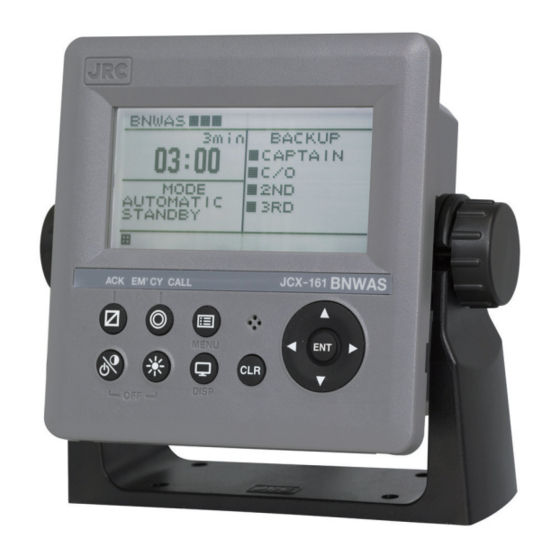
6. Outline drawing JCX-161 BNWAS Installation Manual 6.2 LCD Display unit (NWZ-4650) COLOR : N4 SEMI-GLOSS MASS : APPROX. 0.6kg IP SPEC : IP22 UNIT : mm CATEGORY : Protected LCD Display unit (NWZ-4650) outline drawing (with the desk rack) -
Page 128: Reset Button Unit (Ncj-895)
6. Outline drawing JCX-161 BNWAS Installation Manual 6.3 Reset button unit (NCJ-895) COLOR : N4 SEMI-GLOSS MASS : APPROX. 0.2 kg IP SPEC : IP22 UNIT : mm CATEGORY : Protected Reset button unit (NCJ-895) outline drawing 7ZPNA4321... -
Page 129: Reset Button Unit (Waterproof) (Ncj-896) (Option)
6. Outline drawing JCX-161 BNWAS Installation Manual 6.4 Reset button unit (Waterproof) (NCJ-896) (Option) COLOR : N4 SEMI-GLOSS MASS : APPROX. 0.5 kg IP SPEC : IP56 UNIT : mm CATEGORY : Exposed Reset button unit (Waterproof) (NCJ-896) outline drawing... -
Page 130: Buzzer Unit (Nvs-785)
6. Outline drawing JCX-161 BNWAS Installation Manual 6.5 Buzzer unit (NVS-785) COLOR : N4 SEMI-GLOSS MASS : APPROX. 0.2 kg IP SPEC : IP22 UNIT : mm CATEGORY : Protected Buzzer unit (NVS-785) outline drawing 7ZPNA4321... -
Page 131: Motion Sensor (Nyg-5) (Option)
6. Outline drawing JCX-161 BNWAS Installation Manual 6.6 Motion sensor (NYG-5) (Option) COLOR : N4 SEMI-GLOSS MASS : APPROX. 0.4 kg IP SPEC : IP22 UNIT : mm CATEGORY : Protected Motion sensor (NYG-5) outline drawing 7ZPNA4321... -
Page 132: Led Warning Lamp Unit (Ncd-2257) (Option)
6. Outline drawing JCX-161 BNWAS Installation Manual 6.7 LED warning lamp unit (NCD-2257) (Option) COLOR : N4 SEMI-GLOSS MASS : APPROX. 0.2 kg IP SPEC : IP22 UNIT : mm CATEGORY : Protected LED warning lamp unit (NCD-2257) outline drawing... - Page 134 For further information,contact: Not use the asbestos http://www.jrc.co.jp Marine Service Department Telephone : +81-3-3492-1305 Facsimile : +81-3-3779-1420 e-mail : tmsc@jrc.co.jp AMSTERDAM Branch Telephone : +31-20-658-0750 Facsimile : +31-20-658-0755 e-mail : service@jrceurope.com SEATTLE Branch Telephone : +1-206-654-5644 Facsimile : +1-206-654-7030 e-mail : marineservice@jrcamerica.com...
Need help?
Do you have a question about the JCX-161 and is the answer not in the manual?
Questions and answers