Advertisement
Quick Links
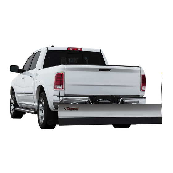
INSTALLATION INSTRUCTIONS
Thank you for purchasing SNOWSPORT
180 Utility Plow. Agri-Cover, Inc. proudly
®
manufactured this snowplow using superior quality materials and workmanship. With
proper care, your snowplow will provide years of service and enjoyment.
NOTICE TO INSTALLER: Even if familiar with hardware, read instructions prior to
installation as improvements may be made without notice. Always handle components
with care. If you have questions or problems, have serial number ready and call
customer service. When done, these instructions must be given to the consumer.
NOTICE TO CONSUMER: Before using snowplow, read safety and operation sections.
Save these instructions for future reference.
FOR YOUR RECORDS
DATE PURCHASED:
WHERE PURCHASED:
SERIAL NUMBER:
(Located on back of snowplow blade)
Questions?
800-689-6612
agricover.com
Advertisement

Related Manuals for AGRI-COVER SNOWSPORT 180


Summary of Contents for AGRI-COVER SNOWSPORT 180
- Page 1 INSTALLATION INSTRUCTIONS Thank you for purchasing SNOWSPORT 180 Utility Plow. Agri-Cover, Inc. proudly ® manufactured this snowplow using superior quality materials and workmanship. With proper care, your snowplow will provide years of service and enjoyment. NOTICE TO INSTALLER: Even if familiar with hardware, read instructions prior to installation as improvements may be made without notice.
- Page 2 PREPARATION Unpack snowplow components. For additional installation assistance, go to mysnowsport.com for install and operation videos. TOOLS NEEDED COMPONENTS • Drill with 5/16” bit • (1) Push frame • 9/16” Socket with ratchet or impact • (1) Straight interceptor kit driver/wrench •...
-
Page 3: Snowplowing Tips
SNOWPLOWING TIPS The SNOWSPORT 180 Utility Plow is designed to make moving snow convenient and ® easy by following simple tips. • Check local regulations before plowing snow. • Always keep current with snowfall. It’s easier to plow fresh snow. •... -
Page 4: Parts Diagram
PARTS DIAGRAM 3/8"-16 x 3/4" Hex bolt Blade marker 3/8" Flat washer Aluminum blade Rubber blade Slide hinge 3/8"-16 x 1" Hex bolt with washer 3/8"-16 x 1" Hex bolt with washer... - Page 5 3/8"-16 Square nut 1/4"-20 x 1-1/2" Carriage bolt Skid bracket 1/4" Flat washer 1/4" Lock washer 1/2"-13 x 4" 1/4"-20 Hex nut Hex bolt Quick pin 1/2" Flat washer Push frame Flat washer 1/2"-13 Hex nut Hair pin Receiver pin...
- Page 6 1. INSTALLING PUSH FRAME NOTE: We recommend performing this (2) Lock nuts with step with two people. One person holds the (2) washers push frame to the interceptor while another Push frame performs the installation. A. Insert interceptor into receiver with push (2) 1/2"...
- Page 7 2: ASSEMBLING SNOWPLOW A. Each end of the rubber cutting edge has two factory marks (to match with holes in skid bracket). Drill them out with 5/16” bit. B. Mount skid bracket as shown to rubber cutting edge. Tighten bolts until head sinks flush with rubber surface.
- Page 8 2. ASSEMBLING SNOWPLOW (Continued) NOTE: Rubber blade should be room temperature before assembling. C. With brackets facing back of blade, align rubber groove with blade mounting channel. D. Slide rubber into channel in bottom of blade and center. TIP: Apply soapy water solution to top of rubber blade and aluminum blade mounting channel for easier assembly.
- Page 9 2. ASSEMBLING SNOWPLOW (Continued) F. Insert (2) square nuts with flat side facing up in top channel of blade end and align with slide hinge top holes. G. Insert 3/8” x 3/4" bolts with 3/4” washers through holes in slide hinge and thread into nuts inside channel.
- Page 10 2. ASSEMBLING SNOWPLOW (Continued) L. Hang 1 end of blade assembly into closest retainer groove on push frame. Repeat for opposite end of blade assembly. M. Insert 1 quick pin in hole, rotate pin just enough to allow through second hole and then rotate back to its secure position.
- Page 11 OPERATING INSTRUCTIONS TO LOWER FOR PUSHING SNOW Step behind and remove quick pin. Lift 1 side of blade out of retainer groove until slide hinge fits over the push frame bar, then lower blade to ground. Secure with quick pin. Repeat for opposite side of blade.
-
Page 12: Manufacturer's Limited Warranty
Goods to be returned must have a pre-authorized RA # (Return Authorization Number) – obtained by calling the number above. Mark the number on the package and ship it freight prepaid to address below. Agri-Cover will pay freight to return goods to sender.
Need help?
Do you have a question about the SNOWSPORT 180 and is the answer not in the manual?
Questions and answers