Table of Contents
Advertisement
Quick Links
D
®
ISP
Stitching & Bindery Products
Machine Model :
Head Serial Number :
Date Purchased /Installed :
MiniStitcher HP
OPERATION AND MAINTENANCE MANUAL
IMSHP-A25.....StitchMaster....115 V....25 Wire
Before using this Stitcher, all operators must study this manual and follow the safety warnings and
instructions. Keep these instructions with the Stitcher for future reference. If you have any questions,
contact your local DeLuxe Stitcher Representative or Distributor.
L
E
UXE
solving your wire stitching needs for 125 years...
Serial Number :
S
TITCHER
C O M P A N Y
I N C .
Advertisement
Table of Contents

Subscribe to Our Youtube Channel
Related Manuals for DeLuxe Stitcher MiniStitcher HP


Summary of Contents for DeLuxe Stitcher MiniStitcher HP
- Page 1 IMSHP-A25..StitchMaster..115 V..25 Wire Before using this Stitcher, all operators must study this manual and follow the safety warnings and instructions. Keep these instructions with the Stitcher for future reference. If you have any questions, contact your local DeLuxe Stitcher Representative or Distributor.
- Page 3 W A R N I N G ! MiniStitcher HP Machine operators and others in the work area should always wear safety glasses to prevent serious eye injury from fasteners and flying debris when loading, operating, or unloading this machine.
-
Page 4: Table Of Contents
Table of Contents Introduction ......................3 Specifications .....................4 Installation .......................5 Pre-Inspection ................5 Inspection ..................5 Set-Up ....................5 Assembly ..................6 Operation ......................7 Wire Threading ................7 Wire Straightening .................8 Adjustments and Settings ..............9 Stitching Process ..................... 11 Solid vs. Moveable Clinching ............11 Trip and Stitch Modes ..............12 Troubleshooting ................13 Maintenance ......................15... -
Page 5: Introduction
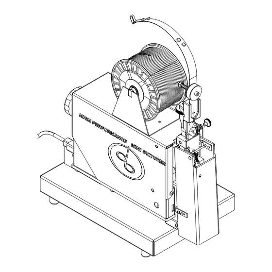
Introduction The DeLuxe Stitcher MiniStitcher HP is a table-top version of the StitchMaster. A completely portable stitcher, the MiniStitcher is ideal for closing padded envelopes, carding, and blister packs. The IMSHP-A25 which operates on 115VAC and conforms to all pertinent CE standards. -
Page 6: Specifications
Specifications Weight Shipping Weight ....50 lbs (22.7 kg) MiniStitcher Machine Unit IMS-A ... . . 36 lbs. (16.2 kgs) IMS- CE . -
Page 7: Installation
Carefully inspect the condition of the shipping container before unpacking your MiniStitcher. If the container is broken or damaged and there is evidence that the machine may be damaged, immediately notify the carrier who delivered the stitcher and the DeLuxe Stitcher Graphic Arts Representative from whom the machine was purchased. -
Page 8: Assembly
Assembly (Figure 2) MG10009A MG10110 25G5 OR 2125G5 UA3804.7 (2) MG10113 PG10211 MG10001A MG10044B PG10293 5160 PG10230 CB889 (4) MG10180 CB328 (4) Figure 2 - Assembly CAUTION Always disconnect the power cord before assembling the MiniStitcher or making any adjustments. Assemble the components of the MiniStitcher. -
Page 9: Operation
cradle. Make sure that the wire payoff is from the top of the spool, as shown in Figure 2. The Wire Guide Spring (MG10009A) slides into the slot in the Wire Guide Spring Bracket (MG10001A) on the top of the Head located at the front of the machine. Once the assembly is complete, turn the machine over by hand a few times using the Shaft Extension Handle (PG10211) located at the rear of the unit. -
Page 10: Wire Straightening
threading process. With the Swivel still removed, power the MiniStitcher on and switch the Trip Mode Switch (PG10232), found on the back of the Machine, to single mode stitching. Replace the Head Guard and trip the Foot switch to allow the wire to automatically thread between the Grip and the Grip Holder. -
Page 11: Adjustments And Settings
straight up and down, adjust the Wire Straightener Nut (9067) so that the Wire Straightener Pointer (9070) turns counter-clockwise. Remember, the MiniStitcher works optimally if the Wire curves slightly to the right. Allow enough Wire to be fed through the Head so that an accurate assessment can be made. - Page 12 Adjusting the Length of the Left Leg (Figure 5) CAUTION Do not operate the MiniStitcher Stitcher until all guards are in place Turn the Face Plate Adjustment Knob clockwise to raise the Face Plate which draws more wire - making the overall length of the stitch longer. If the overall length is too long, turn the Face Plate Adjustment Knob counter-clockwise to lower the Face Plate and decrease the draw of wire pulled from the Wire Spool.
-
Page 13: Stitching Process
Stitching Process The MiniStitcher has been specifically designed to use a solid Clincher Plate. For this reason, adjustable work tables and table trips have not been installed on the MiniStitcher. Following is a brief explanation of options available for the machine. Solid Clinching (Figure 6) The Solid Clincher (MG10178) is attached to the Platform Weldment (MG10170A) on every MiniStitcher. Because the Clincher is mounted to a stationary Clincher Arm, the legs of each stitch... -
Page 14: Trip And Stitch Modes
Stitch Mode The Stitch Mode Switch (PG10232) is found on the back of the MiniStitcher. (The switch on the left, looking from the rear of the machine.) There are two stitching modes: single or continuous. Single stitching is used for production. In the single trip mode only one stitch will be released at a time, no matter how long the trip switch is activated. -
Page 15: Troubleshooting
Trouble Shooting (Figure 7) Following is a brief list of problems and solutions which covers the most common situations encountered when stitching with the MiniStitcher. Most problems with stitches are due to incorrect adjustments on the machine or to the normal wear of parts. : The machine does not cycle but the Main Power Switch (PG1022B) is on. - Page 16 CAUTION Do not operate the MiniStitcher Stitcher until all guards are in place : Right Leg Short problem : Shorten the left leg and then lengthen both of the stitch’s legs. solution (See pages 10 - 11) : Left Leg Short problem : Lengthen the left leg.
-
Page 17: Maintenance
Maintenance Lubrication (Figure 8) Your MiniStitcher has been fully lubricated at the factory, but regular preventative maintenance will result in superior performance and longer life of the machine. A good rule of thumb is to oil the MiniStitcher’s critical points every five pound wire spool change or every month, whichever comes first. -
Page 18: Cleaning
In time, you will need to replace some parts in your MiniStitcher. When this happens, first locate the needed part in one of the following diagrams. Then locate the DeLuxe Stitcher part number and contact your Graphic Arts Representative to order the part by the part number, description and... -
Page 19: Replacing Spare Parts
CAUTION Always disconnect the power cord before any maintenance or adjustments are made to the MiniStitcher Replacing Spare Parts Following are some of the MG10009A more common wear parts MG10011A which will need to be MG10001A removed and replaced in 9115 your MiniStitcher. - Page 20 stitcher head. Remove the Wire Guide Spring (MG10009A) from the Wire Guide Spring Bracket (MG10001A). Loosen the Bonnet Clamp Eccentric Handle (9003A) and remove the Stitcher Head from the MiniStitcher. Place the Head on a clean work area. Be aware that the Driving Shaft Connection Link (2215) is removed from either the Driving Slide Assembly (2137A) or the Crank (MG10031A). ...
- Page 21 Removing and Replacing the Grip (Figure 11) The Grip (9015) can be used in two positions so that when the gripping teeth 9024 show signs of wear, it may be reversed to extend the life of the part. Loosen the Grip 9023 9015 Retaining Clip Screw (9024) and swing the...
- Page 22 Removing and Replacing the Driver (Figure 13) The Driver (9009-25 or 9009-21x25) is also double-ended so that when it is worn, it can be reversed to provide a PG10211 new driving surface and increase the life of the part. The Driver can be removed and replaced without having to remove the Head from the 5160...
-
Page 23: Modifications
MiniStitcher over until the Driver (9009-25 or 9009-21x25) is at the lowest position of its stroke. Adjust the leveling Screws so that the Solid Clincher is brought up level with the bottom of the Driver. Center the Solid Clincher under the Driver and tighten the Screws (UA4808.3). -
Page 24: Appendices
Frame Assembly... - Page 25 Frame Assembly PART No. DESCRIPTION QUANTITY G30173 Self Tap Screw 8 x 3/8 MG10014H Wiring Assembly (115V) MG10028A Circuit Board Platform CB719 Nut 8-32 CG190B Phone Jack P5106 Screw 6-32 x 3/8 CB720 Nut 6-32 CK162 Circuit Board (115V) PG10203 Screw 4-40 x 1/2 PG10216 Circuit Board Spacer...
- Page 26 Cam Switch Assembly...
- Page 27 Cam Switch Assembly PART No. DESCRIPTION QUANTITY MG10027 Cam Switch Mounting Plate MG10030 Clincher Cam MG10032 Control Cam MG10040 Shaft Extension Tube MG10041 Shaft Extension CK230 Washer 1/2 CB720 Nut 6 - 32 PG10205 Spirol Pin 1/8 x 3/4 PG10206 Nylon Bushing 9/16 CT9110 Screw 8 - 32 x 1/2...
- Page 28 The MiniStitcher...
- Page 30 Gear Motor Assembly...
- Page 31 Gear Motor Assembly PART No. DESCRIPTION QUANTITY 2215 Driving Shaft Connection Link HN440.3 Nylon Insert Lock Nut CG13 Hex Nut MG10026 Head Mounting Plate MG10031A Crank Assembly MG10034 Safety Trip MG10035A Guard Arm Assembly MG10037 Guard Spring Rod PG10003 Head Guard PG10006 Gear Motor (115V) PG10006B...
- Page 32 Platform Assembly MG10170A MG10176 P2731 MG10178 PW10.3 CB371A MG10180 PW10.3 (4) UA2804.6 (2) CB371A (4) UA4808.3 CB487A(4) CB889 (4) CB328 (4) PG10276 (4) P8459 (4)
- Page 33 Platform Assembly PART No. DESCRIPTION QUANTITY CB371A Lock Washer 1/4 CB889 Lock Washer 3/8 MG10170A Platform Weldment MG10176 Backstop MG10178 Solid Clincher MG10180 Table Base P2731 Thumb Screw 1/4-20 x 3/4 P8459 Tap Screw 10-24 x 1/2 PG10276 Rubber Bumper 3/4 OD PW10.3 Washer 3/16 UA2804.6...
- Page 34 Tables and Trip Assemblies MG10112 (2) PG10252 2125G5 25G5 PG10251 UA3804.7 MG10110 MG10113 PG10270 PG10271 MG10044B PG10230D...
- Page 35 Wire, Table and Trip Assemblies PART No. DESCRIPTION QUANTITY 2125G5 Wire Spool 21x25 Flat 25G5 Wire Spool 25 Gauge Round MG10044B Cover MG10110 Spool Shaft MG10112 Wire Spool Washer MG10113 Wire Spool Cradle PG10230D Foot Switch with Guard PG10251 Spool Friction Spring PG10252 Spool Clip PG10270...
- Page 36 Stitcher Head - Bonnet Assembly CA9075 CA9056C (3) CT2604 CTT9003C CA2081 (4) CA9127 CA9081 (2) CA9058 CA9034 CTT9002 DBS1132 CA9056A CA9025 CA9163C CT9109 CA9032C CA9022J CA9037 CA9030 (2) CAA9036A CA9043L CA9044A CAA9046D CA9049 CAA9038E CA9048 (2)
- Page 37 Stitcher Head - Bonnet Assembly CA2081 Face Plate Clip Screw CA9022J Grip Release Slide - 1/2 Cr CA9025 Grip Release Slide Adj Lever CA9030 Supporter Guide Plate CA9032C Compression Spring CA9034 Supporter Spring Lever Screw CA9037 Supporter Spring Lever Bushing CA9043L Rotator Holder, M2000 CA9044A...
- Page 38 Face Plate Assembly CAAA2132W CA172 CA9103C (2) CA9065A CAA2132W CA9066A CA9103A CA9124 (4) CA9098 CA9134...
- Page 39 Face Plate Assembly CA172 Screw, Set, Nylon Tip CA9048 Wire Cutter CA9065A Wire Straightener Roll CA9066A Wirte Straightener Eccentric CA9098 Tension Pawl CA9103A Wire Straightener Roll CA9103C Wire Straightener Roll CA9124 Wire Straightener Roll Clip CA9134 Tension Pawl Spring CAA2132W Face Plate...
- Page 40 Wire Guide Spring and Bender Bar CTT2133C2 CA9032C CA9653 CB860B CA9652 CA9651 CA9651 CB651E 850699 (2) CA9103A (2) 9065B MG10013 CA9070 CA9123 (2) CA9067 CA9069 MG10001A CA9068 9066B 9097 CA9022J CA9025 MG10011BA 2215 CT2606 9799 CA9115 CAA2623C CA9112A CA9012M CAA9014J CA168 CA9113A CA9029...
- Page 41 Wire Guide Spring and Bender Bar Assembly Parts 2215 Driving Shaft Connection Link 9065B Wire Straightener Eccentric Roll 9066B Wire Straightener Eccentric 9097 Grip Release Lever Pin 9799 Face Plate Locating Screw 850699 Wire Straightener Roll Clip CA168 Grip Spring CA173 CA9024 Grip Retaining Clip Screw...
-
Page 42: Wiring Schematic
Internal Wiring TABLE TRIP SWITCH .14 in. JACK MOTOR N.C. BLACK BLACK +90VDC FOOT SWITCH 1/4 in. JACK BLACK W/RED GREEN/YELLOW GROUND -0VDC ON/OFF SWITCH CIRCUIT BREAKER BLACK BLACK 115VAC N.C. 115 VAC 1 AMP RATED 50/60HZ WHITE WHITE 115VAC .14 in. -
Page 43: Part Number /Description Cross Reference
Part Number / Description Cross-Reference ITEM NO. DESCRIPTION QUANTITY ITEM NO. DESCRIPTION QUANTITY 0084 Solid Face Plate Clip Screw 9035 Supporter Spring Lever Roll 2001 9036A Supporter Spring Lever Assembly ASMHD251/2 MiniStitcher Head 9037 Supporter Spring Lever Bushing 20ASMHD MiniStitcher Head 9038A Swivel Assembly 2103B... - Page 44 Part Number / Description Cross-Reference ITEM NO. DESCRIPTION QUANTITY ITEM NO. DESCRIPTION QUANTITY 9164B Driving Slide Swivel Operating Pin P2934 Lock Washer 1/4” 9166 Wire Cutter Locating Pin P4990 Power Cord Strain Release 9171 Solid Face Plate Clip P5106 Screw 6-32x3/8 9799 Face Plate Locating Screw P6794...
- Page 45 Part Number / Description Cross-Reference ITEM NO. DESCRIPTION QUANTITY PG10406 2 Pole Circuit Breaker PG10407 Shoulder Washer 1/4 PG10410 Power Cord and Plug PG10411 RFI Filter PG10413 Receptacle PG10418 1/4x90 Degree Terminal PG10419 Circuit Break - 1 Pole PG10421 Power Cord - 115V PW10.3 Washer #10 SW10...
-
Page 46: Optional Equipment
In addition to the standard features offered with the StitchMaster, optional equipment items can be purchased to better accommodate your stitching needs. The following kits can be purchased from your DeLuxe Stitcher Graphic Arts Representative. FSK1 (Figure 16) This heavy duty Floor Stand allows you to... - Page 47 IMSK2 (Figure 17) For those applications which require it, the Contact Trip Kit (IMSK2) is available for the MiniStitcher. Call your DeLuxe Stitcher Graphic Arts Representative for more information. The IMSK2 Contact Trip Kit can be mounted directly onto the MiniStitcher. The Kit can also be used in conjunction with the IMSK3 Work Table Kit by following the assembly instructions included with the Work Table Kit.
- Page 48 the MiniStitcher, along side the Clincher Arm. Make sure the Trip Mode Switch (PG10232), located on the back of the MiniStitcher, is toggled for Contact Trip use and not Foot Switch use. Plug the Power Cord (PG10421) into a wall outlet and toggle the Power Switch (PG10228B) to the on position. Trip the MiniStitcher by inserting the stock to be stitched under the stitcher head until the stock bumps into the silver Contact Trip Slide and activates the stitcher.
- Page 49 PG10244 (2) Figure 17 - IMSK3 Work Table Kit IMSK3 (Figure 18) For those applications which require it, a Work Table Kit (IMSK3) is available for the MiniStitcher. Call your DeLuxe Stitcher Graphic Arts Representative for more information. In order to mount the ISMK3 Work Table Kit onto the MiniStitcher, complete the following steps. Remove the Table Base (MG10180) from the bottom of the stitcher by removing the four (4) Screws (UA6116.1) and Washers (LW12.2 and PW14). Lay the stitcher on its side with the Clincher Arm hanging off the edge of a table.
-
Page 52: Warranty
This warranty is in lieu of all other express warranties. Any warranty of merchantability or fitness for a particular purpose is limited to the duration of this warranty. DeLuxe Stitcher shall not be liable for any incidental or consequential damages. -
Page 53: Declaration Of Conformity
EN 60204-1:1992 prEN 894-1:1992 prEN 953:1992 EN 294:1992 prEN 894-3:1992 EN 55014:1193 prEN 614-1:1991 prEN 1050:1993 EN 55104:1995 DeLuxe Stitcher Company Executed for this day of in the year first March 1999 Frank P. Cangelosi Signature... - Page 54 NOTES:...
- Page 56 TITCHER ® C O M P A N Y I N C . Stitching & Bindery Products 3747 Acorn Lane • Franklin Park • Illinois 60131 Phone: 847-455-4400 • 800-634-0810 Fax: 847-455-4900 • 800-417-9251 http://www.deluxestitcher.com DBSIMSHP-1215...
Need help?
Do you have a question about the MiniStitcher HP and is the answer not in the manual?
Questions and answers