Table of Contents
Advertisement
Quick Links
D
L
E
UXE
Machine Serial Number :
Head Serial Number :
Date Purchased :
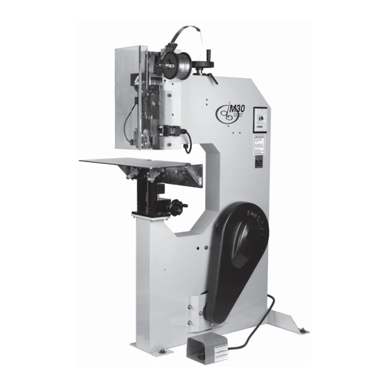
Model M30 Stitchers
OPERATION AND MAINTENANCE MANUAL
M30-AST Stitcher...............115V and 60HZ
M30-BST Stitcher...............230V and 50HZ
Before using this Stitcher, all operators must study this manual and follow the safety
warnings and instructions. Keep these instructions with the M30 Stitcher for future
reference. If you have any questions, contact your local DeLuxe Stitcher Graphic Arts
Representative or Distributor.
S
TITCHER
C O M P A N Y
I N C .
Advertisement
Table of Contents

Subscribe to Our Youtube Channel
Related Manuals for DeLuxe Stitcher M30 Series


Summary of Contents for DeLuxe Stitcher M30 Series
- Page 1 Before using this Stitcher, all operators must study this manual and follow the safety warnings and instructions. Keep these instructions with the M30 Stitcher for future reference. If you have any questions, contact your local DeLuxe Stitcher Graphic Arts Representative or Distributor.
- Page 3 THANK YOU FOR CHOOSING THE MODEL M30 FOR YOUR BINDING NEEDS.
- Page 4 W A R N I N G ! Model M30 Stitchers Operators and others in the work area should always wear safety glasses to prevent serious eye injury from fasteners and flying debris when loading, operating, or unloading this machine. Do not operate this stitcher without all guards in place.
-
Page 5: Table Of Contents
Table of Contents Specifications .......................4 Recommended Wire Sizes ..................6 Introduction .......................7 Installation .......................8 Assembly ..................9 Operating Adjustments Wire Threading ................13 Wire Straightening ...............14 Adjusting the Machine for Thickness of Work ......15 Adjustments and Settings Adjusting the Left Leg ..............15 Adjusting the Clincher Points ............16 Adjusting the Machine for Stab Stitching ........18 Maintenance Lubrication ..................19... -
Page 6: Specifications
Specifications Weight Shipping Weight ....670 lbs [304 kg] Wire Spool ....5 lbs. [2.3 kgs] or 10lbs. [2.6 kgs] optional Foot Switch . -
Page 8: Recommended Wire Sizes
Recommended Wire Sizes (Figure 1) The wire sizes that can be used on the M30 as well as recommended uses are listed below. Note that when size changes, several parts on the Head will have to be changed to accommodate the wire size change. -
Page 9: Introduction
Introduction The DeLuxe Stitcher M30 Stitcher Machine is a single-head stitcher designed to accommodate both light and heavy-duty work, stitch both flat and saddle work and can reliably stitch any thickness of stock from 2 sheets to 1-1/4” (30mm). It even stab stitches up to 2” (50mm) of material. The recom- mended wire sizes to be used on the M30 are: 20 to 25 gauge round wire and 20x24, 20x25, 21x25, 19x21-1/2 and 18x20 flat wire. -
Page 10: Installation
Stitcher. If the container is broken, damaged or has been tipped over and there is evidence that the machine may be damaged, immediately notify the carrier who delivered the machine and the DeLuxe Stitcher Graphic Arts Representative from whom the M30 was purchased. Inspection As you carefully unpack the machine, check to make sure all components were delivered and are in good working order. -
Page 11: Assembly
Assembly (Figures 2-7) Tools required: 4mm & 6mm Hex Wrenches Flat Head Screwdriver 1. Remove Face Guard by lifting to disconnect it from Safety Switch and then pulling it away. 2. Remove screws & washers from shown locations. Face Guard M6 Socket Screw G40809 (2) M6 Lock Washer... - Page 12 3. Attach the Upper Wire Straightening Bracket and the Wire Spool Mounting Bracket. 4. Attach the Spool Stud to the Bracket. 5. Install Wire Spool. Secure with the Set Collar and Thumb Screw. 6. Re-attach the Face Guard. Wire Straightener G40767AA Wire Guide Spring G40286A...
- Page 13 Table Pivot Shaft G40962 7. Prepare Work Table for install by disassembling the Work Guides. 8. Remove Table Pivot Shaft. Figure 4 - Assembling Figure 5 - Assembling Work Table Assy. G40964A 9. Install Work Table. Table Pivot Set Screw Shaft UA1428.1 G40962...
- Page 14 Figure 6 - Assembling WARNING Always disconnect the power supply before making any adjustments or servicing the stitcher.
-
Page 15: Wire Threading
Wire Threading (Figures 8 - 10) Figure 8 - Wire Threading Wire Guide Studs Figure 9 - Wire Threading 1. Pull wire off the spool and thread through the studs in the Wire Guide Spring Assy. (Fig. 8) 2. Continue between the Tension Pawl and its roller and through two sets of wire straightener rollers (Fig. -
Page 16: Wire Straightening
Wire Straightening (Figure 11-14) 1. Once through, turn each of the four Adjustable Straightener Rollers until they’re just touching the wire. 2. Cycle the machine sev- eral times and notice which direction the wire is curving out of the Cutter Box (Fig. 11). -
Page 17: Adjusting The Machine For Thickness Of Work
Adjustments and Settings Adjusting for Thickness of Work & Legs (Figure 15-17) Figure 14 - Adjusting for Thickness of Work M6 Screws G40818 (2) LOOSEN Cutter Box Adjustment Slide G40642 SHORTER LONGER LEFT LEG LEFT LEG Adjuster Lock Lever Hand Wheel G40772 G30128 Cutter Box Assy. -
Page 18: Adjusting The Clincher Points
Adjusting The Clincher Point Height (Figures 17) Figure 17 - Clincher Point Height 1. With the Work Table in the flat work position, check the clinch by manually cycling the machine to the point of clincher activation. 1/16” [1.5mm] Max. out of plate. - Page 19 form a piece of wire so that it protrudes out past the Formers. (Best done when thickness is set to 1/4” [6mm]) 6. Move the Clincher Base Work Table Assy. until the front of G40964A Clincher Plate & Driver are centered and from the side the Former grooves and Driver are likewise.
-
Page 20: Adjusting The Machine For Stab Stitching
Adjusting for Stab Stitching (Figures 20-21) Clincher Upright Clincher Pad Extension G40950AA G40975 Clincher Slide Adjustment Screw 18186 Flat or Saddle Stitch Stab Stitch Indicator 9070 M6 Shoulder Screws 1. With the Work Table G40820 (2) in the flat work posi- tion, remove the (2) M6 Shoulder Screw that attach the Clincher... -
Page 21: Maintenance
Maintenance Lubrication (Figures 22-23) NOTE: Lubricate regularly instead of excessively. Thoroughly oil the Felt Figure 22 - Lubrication Points Tension Washer and for all else, Pawl Roller G20285 use only one or two drop of any standard S.A.E. Tension Pawl Pivot Stud #10 oil in the areas shown. -
Page 22: Troubleshooting
Troubleshooting (Figure 24) The following is a brief list of problems and solutions which should cover the majority of situations encountered when stitching with the M30. The quality and quantity of work that can be produced with the M30 Stitcher is dependent upon the operator making all adjustments as accurately as possible and carefully maintaining the machine. - Page 23 : Left Leg Short PROBLEM : Lengthen the left leg by loosening the two screws on the Cutter SOLUTION Box Adjustment Slide, and moving the Cutter Box to the left. : Left Leg Long PROBLEM : Shorten the left leg by loosening the two screws on the Cutter SOLUTION Box Adjustment Slide, and moving the Cutter Box to the right.
-
Page 24: Cycling Machine Manually
Belt Guard Removal & Cycling Machine Manually / Adjusting the V-Belt (Figures 26-28) 1. To remove the Belt Figure 27 - Locating the Actuator Lever Guard cover, push down Control Collar Cam on the (4) rounded tabs 850888 while pulling away the cover. -
Page 25: Cleaning
2. To manually cycle the machine, first locate the Actuator Lever on the Wrap Spring Clutch and push it where shown (in Fig 9) to pivot it away from the Control Collar Cam. Rotate Drive Pulley (as shown by the arrows on it, see Fig. 10) for one cycle. Repeat as necessary. 3. -
Page 26: Disassembling The Head
Upper Wire Feed Gear Screw Straightener Bracket Lower Wire Bracket M6x1.0x50 G40767AA Tube Assy G40536 G40802 (3) G40599A Wire Spool Head Guard Mounting G40135 Bracket Wire Holder G40520 Retaining Spring G20583 Socket Head Screw G20697 (3) Knurled Thumbscrew Upper Wire G40773 Straightener Bracket G40716AA... -
Page 27: Ordering & Replacing Spare Parts
In time, you will need to replace some parts in the M30 Stitcher Machine. To do this locate the DeLuxe Stitcher part number in one of the following diagrams and contact your Graphic Arts Representative to order the replacement by part number, description and quantity. - Page 28 Removing and Replacing the Clincher Clincher Point Points and Clincher Clincher Back G40955R (Round) Clincher Plate Assy. Slide G40955F (Flat) Front Plate G40952A G40954 The Clincher Points are not reversible as with other styles, but are easy to replace. Screw M6x1.0x20 1.
- Page 29 Adjusting and Replacing the Cutters Cutters become worn or chipped and must be adjusted or replaced. The Fixed Cutter must be replaced when worn. The Moving Cutter can Cutter Box Assembly be adjusted 3 or 4 times before need- G40597A ing replacement.
- Page 30 Driver Bar G40551B M6 Cap Screw G40809 (4) Driver Retaining Screw G40809 Bender Bar walls Former (2) Driver Figure 35 - Changing the Driver Figure 36 - Changing the Formers Replacing the Formers & Driver The Driver and Formers must be replaced when worn or when changing wire size. Replace them as follows: 1.
- Page 31 Large Feed Gear Feed Gear Large Feed Gear Set Screw Friction Bushing G40510A G20691 G20694 Feed Gear Clutch Feed Gear Friction Plug G40537 Friction Spring G20587 G20586 Large Feed Upper Wire Tube Feed Gear Shaft Gear Washer G40581 Rear Feed G40114 G40129 (2) Gear Spacer...
- Page 32 necessary. 9. Lift the top Large Feed Gear Washers, the Large Feed Gear and the Feed Pinion off the Feed Gear Shaft and away from the Feed Gear Bracket. 10. Remove the Feed Pinion and Rear Feed Gear Spacer from the Large Feed Gear. If necessary, liberally apply Kluber ISOFLEX NBU 15 grease to the Feed Pinion Bearings and/or the Feed Gear Clutch and rub into the rollers using your finger and reassemble.
- Page 33 3. Push the M6 Dowel out the right side of the Supporter. 4. Remove the Bender Slide Pin Block Assy. from the the Bender Bar. 5. To disassemble the Bender Slide Pin Block Assy., place it in a vise. Clamp the bottom of the Bender Slide Pin Block and the top of the Bender Slide Block.
- Page 34 3. Remove the Feed Rack by holding the Feed Rack Block and turning the Feed Rack Adjustment Knob counter-clockwise until the Rack comes off the Feed Rack Adjustment Stud. 4. Remove the Feed Release Cam (G40638). WARNING Do not operate the M30 under power until the machine has been turned over manually to verify that the stitching head is operating freely.
-
Page 35: Clutch-Brake Maintenance
Clutch-Brake Maintenance WARNING Always disconnect the power supply before making any adjustments or servicing the stitcher This stitcher is equipped with a solenoid actuated, continuous trip, wrap spring clutch-brake unit. It is a dependable device and seldom needs service. But should a malfunction occur, the following information is a service and troubleshooting guide for the maintenance of this unit. - Page 36 Clutch and Brake Springs With the brake engaged (full limit of output), the input hub should be free to rotate by hand. With the clutch engaged, the input and output hubs should rotate together. If the unit does not rotate in either of these modes, the clearance between the hubs of the unit on the shaft may have been disturbed or damaged.
- Page 37 Disassembly (See figure 42) To disassembly the Clutch-Brake unit (850673 or 850674) it will be necessary to remove the Drive Pulley (7678) from the stitcher by removing the V-Belt (850730), Retaining Ring (P7863), and Clutch Anchor Screw (7681). Disconnect the Ground and Solenoid wires, and swing the anchor strap (FC9656) clear of the Drive Pulley Assembly and slide it off of the Drive Shaft.
- Page 38 Note: At this point it may be necessary to reselect one (1) of the nine (9) Control Collar slots for the Brake Spring Tang (release Actuator Lever, remove the Clutch Spring tang from the slot, then move Control Collar axially toward the Input Hub end and rotate it opposite to the drive direction to pick up the next slot).
- Page 39 Lubrication The clutch-brake unit is designed with the bearing parts made from sintered metal that has been impregnated with oil and normally do not need to be re-lubricated. In cases where there is severe duty, the unit may be re-oiled or flushed out with minimal or no disassembly by using a light bearing oil as used in manufacture (Shell Bearing Infusion Oil #33).
-
Page 40: Assembly Drawings
The M30 Stitcher Machine... - Page 42 Internal Assemblies - Compression Adjustment Linkage G40770 (3) G40101 G40768 (LONG) G40013A G40017A G40769 (2) (SHORT) G40814 G30053 (5) G40909 REMOVABLE G40242 PANEL THIS SIDE G40537 G40240A G40238B (See page 48)
- Page 43 Internal Assemblies - Upper Driver Components...
- Page 44 Internal Assemblies - Lower Drive Gear & Bearing Mounts Lower Drive Gear Bearing Mounts...
- Page 45 Internal Assemblies - Clincher Cam & Clincher Lever Assemblies G40811 G40759 G30007B G40301 G30064 G40758 G40815 G30054 G40975 G40905 G40820 (2) G40703 G20128 G40043A AF223 G30063 G40702 G40037A G40174 G40810...
- Page 46 Table and Clincher Assemblies - Clincher Mount & Work Table 7423C (2) G20520 (4) 63 (4) G40964A G20697 (4) G40962 G40977A (2) (OPTIONAL) UA3810.10 (2) B554 (2) UA1428.1 (2) PW10.3 (2) 7648 (2) HN1024 (2) 072006 (2) G40960 G40755 (2) G40756 G40959 G40852...
- Page 47 Table and Clincher Assemblies - Clincher Pad...
- Page 48 Motor Assemblies...
- Page 49 Guard Assembly...
- Page 50 External and Head Assemblies - Head Crank & Driving and Bending Cam G40812 G40851 Note: Chamfers should face each other G40908 (2) G40237 G40238B G40763 G40824...
- Page 51 External and Head Assemblies - Hand Wheel Assembly G30128 G20520 G40803 UA4810.1 (3) G20520 (3) G30099B G40100 G40208A G40102 G40821 AF207 PW12.1...
- Page 52 External and Head Assemblies - Bonnet Plates...
- Page 53 External and Head Assemblies - Feed Slide and Bender Bar G20615 G20578 G20179 G20573 G40530 071004 G40574 072003 (2) G20576 G40531BA G40527B G20520 G40672 G40638 G40754 (2) G20625 (2) 042001 (2) G40752 G40803 (2) G40569 G40563 G20520 (2) G40562 071006 (2) G40803 G20520 15025L...
- Page 54 External and Head Assemblies - Feed Lever & Feed Gear Bracket G20668 G40262 G40512 G20267 G40532A G40901 (2) G40904 G40751 G20691 G40710A G40581 G20694 G40823 (2) G20586 G20118 G20587 G20264 G40536 G20520 (3) G40119 G40114 (2) G20522 (4) G20121 G40802 (3)
- Page 55 External and Head Assemblies - Cutter Box & Cutter Operating Lever G40904 (2) G40571 G20515 G40630B G40800...
- Page 56 External and Head Assemblies - Large Feed Gear & Lower Wire Straightener G40129 (2) G40538 (2) G40511A G40128 G40510A G40537 G20283 G20226 (2) G40716A G20311 G20282 (2) G40284 G20219 (4) G20290 (2) G50234 (5) G40765 (2) G40912 G20140 (2) G40766 G20520 (2) G40773 G40809 (2)
- Page 57 External and Head Assemblies - Pivot Block & Wire Holder G40643BA G20520 (3) G20697 (3) G40709 G20520 (2) G40571 G20520 072013 (2) G40680 (5/8”) G20617 G40681 (1/2”) 072004 G20661 G20579 G20175 G20167 (2) G20541 G20184 G20542B G20135 G20255 G20665 G20252 G20254 G20659BA G20253...
- Page 58 External and Head Assemblies - Wire Guide Spring G20288 (2) G20140 (4) G40286A G20234 (6) G50234 (3) G20283 G20290 (2) G20284 G20311 G20282 (2) G20297 G20219 (12) G20226 (6) G40766 (3) G40767A G40912 (3) G40765 (4) G20292 (2) G20287 G20520 (2) G20293 (2) G20298 G40809 (2)
- Page 59 External and Head Assemblies - Head Guard G20520 (2) G40809 (2) G20171 (2) G40851 (2) G40599A G40135 G40823 (2) UA3806.9 88038 KN1032 (2) PW14 (2) G20274 (2) 850343 850319B G40402 (2) UA3410.4 (2) G30124...
-
Page 60: Part Number / Description Cross-Reference
Part Number / Description Cross-Reference PART NO. DESCRIPTION QUANTITY PART NO. DESCRIPTION QUANTITY 851005 Strain Relief 042001 Screw M5x.8x8 071004 Lock Washer Ribbed 85128 Connector 3/8 071005 Lock Washer Ribbed M4 85982 Lock Nut 1/2 071006 Lock Washer Ribbed M5 86243 Power Cord - 115V 072003... - Page 61 Part Number / Description Cross-Reference PART NO. DESCRIPTION QUANTITY PART NO. DESCRIPTION QUANTITY G30117B Motor Cover G20297 Screw M6x1.0x40 G30118 Belt Guard Bracket G20298 Nylock Lock Nut, M6x1 G30119B Adjuster Gauge G20311 Spring Anchor Screw G30124 Actuator Key Bracket G20360 Hex Key Wrench 3.0mm G30127 Starter Mounting Flange...
- Page 62 Part Number / Description Cross-Reference PART NO. DESCRIPTION QUANTITY PART NO. DESCRIPTION QUANTITY G40262 Small Feed Gear Shaft G40656 Driver 5/8 - 20x24 Wire G40284 Lower Tension Pawl Spring G40657 Driver 5/8 - 19x21-1/2 Wire G40286A Wire Guide Spring G40658 Driver 5/8 - 20 Wire G40301 Drive Cam Gear...
- Page 63 Part Number / Description Cross-Reference PART NO. DESCRIPTION QUANTITY PART NO. DESCRIPTION QUANTITY G40811 Screw M6x1.0x8 - Dog Point HN1420.2 Hex Jam Nut 1/4-20 G40812 Screw M8x1.25x16 - Low Head HN3816 Hex Nut 3/8-16 G40813 Shoulder Screw HN51618 Hex Nut 5/16-18 G40814 Shoulder Screw HN51618.2...
- Page 64 Wiring Diagram Complete Wiring with Detail...
- Page 65 Wiring Diagram AST - 115V Models BST - 230V Models...
- Page 66 NOTES...
-
Page 69: Warranty
This warranty is in lieu of all other express warranties. Any warranty of merchantability or fitness for a particular purpose is limited to the duration of this warranty. DeLuxe Stitcher shall not be liable for any incidental or consequential damages. -
Page 70: Declaration Of Conformity
Declaration of Conformity DeLuxe Stitcher Company 6635 West Irving Park Road Chicago, Illinois 60634-2410 U.S.A Telephone 773-777-6500 Facsimile 773-777-0156 hereby declare under our sole responsibility that the Stitching /Stapling Machines M30-BST to which this declaration relates is in conformity with the... - Page 72 DBSM30-0908...
Need help?
Do you have a question about the M30 Series and is the answer not in the manual?
Questions and answers