Table of Contents
Advertisement
Advertisement
Table of Contents

Related Manuals for TAC 2112


Summary of Contents for TAC 2112
- Page 1 TAC 2112 Manual 0-004-7459-3 (GB), 1999-08-01...
-
Page 3: Table Of Contents
1.1 Overview............................1:1 1.2 How to use this manual ......................... 1:1 1.3 Associated documentation ......................1:2 2 TAC 2112 heating controller ........................2:1 3 Using the operator’s panel .......................... 3:1 3.1 Introduction........................... 3:1 3.2 What is shown in the display window? ..................3:1 3.2.1 Parameter numbers and parameter values.............. - Page 4 TAC 2112, Manual Contents 7 Functional description ..........................7:1 7.1 Introduction........................... 7:1 7.2 Controller operating modes......................7:1 7.3 Heat control........................... 7:4 7.3.1 Functional diagram ...................... 7:4 7.3.2 Damped outdoor temperature..................7:5 7.3.3 Reset curve for outdoor compensation................. 7:5 7.3.4 Automatic adjustment of the reset curve ..............7:6 7.3.5 Supply controller......................
-
Page 5: About This Manual
Here you will find a detailed description of all the functions and parameters of the controller. Chapter 8, Technical data All the technical data for the TAC 2112 can be found here. Appendix A, Commissioning protocol/list of parameters Here you will find a commissioning protocol, which also provides support for adjustment of the controller. -
Page 6: How To Use This Manual
TAC 2112, Manual About this manual How to use this manual The TAC 2112 Manual describes all the functions and procedures necessary to install, adjust and use the controller. The TAC controller, as well as other products from the 2000-range, should not be used for purposes other than intended for. -
Page 7: Tac 2112 Heating Controller
TAC 2112, Manual TAC 2112 Heating Controller TAC 2112 Heating Controller The TAC 2112 is a digital heating controller for controlling waterborne heat in buildings. The radiator circuit is controlled according to an outdoor temperature- compensated reset curve, with or without a reference sensor. - Page 8 TAC 2112, Manual TAC 2112 Heating Controller The TAC 2112 is designed to control heat in apartment buildings, offices, schools and other large buildings. Installation with district heating The controller operates both with and without reference sensors. However, some optimisation functions require a reference sensor to be installed.
-
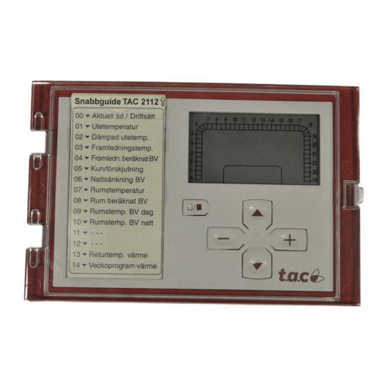
Page 9: Using The Operator's Panel
TAC 2112, Manual Using the Operator´s Panel Using the Operator’s Panel Introduction This chapter shows you how to use the buttons on the operator’s panel and the display window to read off and set parameters such as temperatures. What is shown in the display window? The display window provides you with information from the heating installation in the form of digits and symbols. -
Page 10: Parameter Numbers And Parameter Values
TAC 2112, Manual Using the Operator´s Panel 3.2.1 Parameter numbers and parameter values The controller has a list of 100 parameters numbered from 0 to 99. Some of these parameters can be set (such as the setpoint for supply temperature), while others can just be read (such as the outdoor temperature). -
Page 11: Operating Modes
TAC 2112, Manual Using the Operator´s Panel 3.2.2 Operating modes The different operating modes of the controller are shown in the display window using the symbols below. 9 10 11 12 13 14 15 16 17 12:00 P 00 °C°F... -
Page 12: Weekly Program
TAC 2112, Manual Using the Operator´s Panel 3.2.3 Weekly program The weekly program for daytime and night operation is displayed in the form of a 24-hour time bar from 00:00 to 24:00. Filled segments show the time of day when daytime operation is to be effected. -
Page 13: Outputs From The Controller
TAC 2112, Manual Using the Operator´s Panel 3.2.4 Outputs from the controller The controller has a number of outputs for the control of external units (such as the actuator for the heating valve). When an output is activated, its symbol is displayed in the display window. -
Page 14: How Are The Buttons Used
TAC 2112, Manual Using the Operator´s Panel How are the buttons used? The controller has five buttons beneath the display window. Daytime/night operation Increase/decrease weekly program parameter value Select parameter The buttons on the operator’s panel buttons are used to select a parameter. -
Page 15: Day-To-Day Usage
TAC 2112, Manual Day-to-day Usage Day-to-day Usage Introduction This chapter provides sufficient information for you to read off and set temperatures and other parameters during normal operation. All parameters and functions are described in detail in Chapter 7, “Functional description”. -
Page 16: Setting Temperatures
TAC 2112, Manual Day-to-day Usage Setting temperatures Procedure for setting a temperature: Select parameter number (P No.) by pressing 9 10 11 12 13 14 15 16 17 shown in the list below. The parameter number is increased and -10.0... -
Page 17: Setting The Time Schedule For Daytime/Night Operation
TAC 2112, Manual Day-to-day Usage Setting the time schedule for daytime/night operation 4.5.1 Weekly program for night setback of heat When the controller is supplied, it is set for night setback of heat between 22:00 and 06:00 for all days of the week. See chapter 7 for a more detailed description of the time schedule. -
Page 18: Weekly Program For External Units
TAC 2112, Manual Day-to-day Usage Go to P 65 by pressing 9 10 11 12 13 14 15 16 17 Set the end date (month.day) by pressing 01.01 P 65 Exit by pressing Procedure for deleting a holiday period: Select parameter number P 63 by pressing . -
Page 19: Reading Alarms
TAC 2112, Manual Day-to-day Usage Reading alarms When an alarm has been triggered, the symbol in the display window will flash. The display window will also specify what has triggered the alarm. Procedure for reading off alarms: Select parameter number (P No.) by pressing 9 10 11 12 13 14 15 16 17 shown in the list below. -
Page 20: Setting The Clock
TAC 2112, Manual Day-to-day Usage Setting the clock To display the current time on the clock, select parameter P 00 (usually displayed). The clock must be set after a power cut lasting more than 48 hours. See chapter 7 for a more detailed description of the clock. -
Page 21: Installation
TAC 2112, Manual Installation Installation Assembly Controller Position the controller so that it is easy to read off and set values and so that the cover can be opened. The permissible ambient temperature range and humidity range must not be exceeded (see Technical data, chapter 8). - Page 22 TAC 2112, Manual Installation Procedure for removing the backplate: Remove the metal brace by unscrewing the fastening device. Press in the two round “buttons” on the sides of the controller. Hold the “buttons” in while carefully pulling the electronic part out of the back.
- Page 23 TAC 2112, Manual Installation Procedure for mounting controller in a panel: Make an opening in the panel as shown in the adjacent scale drawing. The max. panel thickness is 5 mm. +0,5 2. Remove the backplate from the electronic part (see above).
- Page 24 TAC 2112, Manual Installation Procedure for mounting controller on a wall: Drill holes for the three screws as shown in the scale drawing below. Remove the backplate from the electronic part (see above). Mount the backplate and the metal brace.
- Page 25 Mount the sensor to an exterior wall facing north or north-west. Place it approximately 3 m above ground with the cable entry facing down. If several TAC 2000 are to be used in the same building, it may be sufficient to mount only one outdoor temperature sensor. A controller which has no outdoor temperature sensor of its own can then receive outdoor sensor signals from the controller which has one.
-
Page 26: Connection
TAC 2112, Manual Installation Connection All equipment which is connected to the controller must comply with the following standards: • EN 60 742 (or other applicable safety standard) for air handlers which provide ELV-type power supply (normally 24 V AC) to the controller and other connected equipment. - Page 27 Installation The outdoor temperature signal (Y2) is connected to the input of the outdoor temperature sensor (B2) in the controllers (TAC 2000) which have no outdoor sensor of their own. If the SPC signal is connected from equipment which has a different transformer, the G0s from each transformer must be connected to one another.
- Page 28 The following applies when the 24 V transformer is placed by the TAC 2112: The cables to G, G0 and other terminal blocks on TAC 24 V actuators must not exceed 50 m in length, and shall have a minimum cross- sectional area of 0,8 mm .
- Page 29 TAC 2112, Manual Installation 5.3 Starting up Before the power is switched on The following should be carried out before switching on the power: Check that sensors and actuators are connected correctly. Set the changeover switch to configuration. It is possible to gain access to the changeover switch by pulling out the quick reference and removing the plastic disk in front of it.
- Page 30 TAC 2112, Manual Installation Close input X1 (forced night setback) to measurement neutral (M) and check that the clock and the flashing moon appear in the display window. Close input U3 (pump alarm) to measurement neutral (M) and check that the alarm symbol ! appears in the display window.
-
Page 31: Troubleshooting
TAC 2112, Manual Troubleshooting Troubleshooting The TAC 2112 is usually a very reliable controller. If problems occur in spite of this, you can use the troubleshooting advice given below. If you require further assistance, please contact your nearest TAC service point. - Page 32 TAC 2112, Manual Troubleshooting Problem Check (that) ... • The calculated setpoint does the effect from the remote heating not seem to be correct control (SPC, P 80) is reasonable • The pump is not running if the pump has stopped due to a...
-
Page 33: Functional Description
TAC 2112, Manual Functional Description 7 Functional Description Introduction This chapter contains a description of all the functions in the controller. At the end of each section is a list of parameters. How to read off and set these parameters is described in Chapter 3, “Using the operator’s panel”. - Page 34 TAC 2112, Manual Functional Description Forced night setback When the controller is in the “timed operation” operating mode and the input X2 is connected to M (measurement neutral), the following takes place: • The symbols on the left are displayed in the display window (the moon flashes).
- Page 35 TAC 2112, Manual Functional Description Manual control When the controller is in the “manual control” operating mode, the following takes place: • The symbol on the left is displayed in the display window. • All relay outputs except for Open heating valve and Close heating valve are activated (the contacts are closed).
-
Page 36: Heat Control
TAC 2112, Manual Functional Description Heat control 7.3.1 Functional diagram The TAC 2112 can control heat with or without a reference sensor. The control function both with and without a reference sensor is described in the illustrations below. Time program... -
Page 37: Damped Outdoor Temperature
TAC 2112, Manual Functional Description 7.3.2 Damped outdoor temperature The object of controlling the supply temperature is to maintain the correct room temperature irrespective of the outdoor temperature. The heat storage capacity of the building shell means that a change in the outdoor temperature affects the room temperature only after a certain time. -
Page 38: Reset Curve For Outdoor Compensation
TAC 2112, Manual Functional Description 7.3.3 Reset curve for outdoor compensation The correct amount of heating is supplied to the building throughout the year by allowing the supply temperature to be changed as a function of the damped outdoor temperature. This function is described by the reset curve. -
Page 39: Automatic Adjustment Of The Reset Curve
TAC 2112, Manual Functional Description 7.3.4 Automatic adjustment of the reset curve In systems with reference sensors, the controller can adjust the reset curve automatically. The temperature at the reference sensor is used to continually carry out small corrections (±1 C) to the three points °... -
Page 40: Supply Controller
TAC 2112, Manual Functional Description Criteria for automatic curve adjustment The following criteria must be met for the automatic curve adjustment to work: • A reference sensor is installed. • Automatic curve adjustment is on (P 27). • The controller is working under timed operation. -
Page 41: Room Controller
TAC 2112, Manual Functional Description The following data apply for the supply controller: P band: 10–200 ° I time: 2 minutes Dead zone: ° The supply setpoint is set to Min. supply temperature (P 22) when the pump is stopped in order to ensure that the valve moves into the closed position. -
Page 42: Return Temperature Limitation
TAC 2112, Manual Functional Description Parameters P No. Parameter Min. Max. Step Default Comments P 07 Room temperature 0 °C 45 °C 0,1 °C With reference sensor only P 08 Calculated SP, room temp. –35 °C 70 °C 0,1 °C... -
Page 43: Remote Heating Control (Spc)
TAC 2112, Manual Functional Description Parameters P No. Parameter Min. Max. Step Default Comments P 13 Return temperature, heating 0 °C 120 °C 0,3 °C Step=0,1 at 2–55 °C P 43 Return limitation on/off 0 (off) 1=heating, 2=heat.+dom.h.w. P 44 Return limit., heating, P band 10 °C... -
Page 44: 7.3.9 Pump Control
TAC 2112, Manual Functional Description 7.3.9 Pump control The pump control acts to utilise the heat accumulated in the building as efficiently as possible by allowing the circulation pump to operate only when there is a specific heating requirement. Pump stop The circulation pump is stopped and the setpoint for the supply temperature is set to Min. -
Page 45: Variable Night Setback
TAC 2112, Manual Functional Description 7.3.10 Variable night setback To ensure that the heating installation is able to reset the room temperature after a night setback in the event of a low outdoor temperature, the controller uses what is known as variable night setback. - Page 46 TAC 2112, Manual Functional Description Without reference sensor Without a reference sensor, the heating time varies with the damped outdoor temperature according to the curve below. Heating time (minutes) P 37 P 38 P 39 Damped 10 15 20 Curve for morning heating...
- Page 47 TAC 2112, Manual Functional Description Example Setpoint room=21 ° Room temperature=18 ° Damped outdoor temperature=10 ° The above results in a deviation of (18–21) C=–3 C. The ° ° y-value of the curve at +10 C is 20 minutes, which gives a °...
-
Page 48: Reduced Daytime Operation (Optimised Stop)
TAC 2112, Manual Functional Description 7.3.12 Reduced daytime operation (optimised stop) In systems with a reference sensor, the controller can determine whether a transition to night operation can take place earlier than the time set. The controller calculates a new transition time on the basis of the deviation in room temperature. -
Page 49: Extended Daytime Operation
TAC 2112, Manual Functional Description 7.3.13 Extended daytime operation Daytime operation can be extended by means of an integral timer. This timer is started from outside, e.g. from an external pressure changeover switch which momentarily connects input X1 to M (measurement neutral). -
Page 50: Clock
TAC 2112, Manual Functional Description Clock The controller contains a calendar clock with automatic transition between daylight saving time and normal time and automatic compensation for leap years. The clock must be set manually after a power cut lasting more than 48 hours. -
Page 51: Time Schedules
TAC 2112, Manual Functional Description Time schedules The TAC 2112 includes two weekly programs and a yearly program (holiday program). Weekly program 1 is used to reduce the room temperature during night operation. Weekly program 2 is used to control external units (via output K4). -
Page 52: Memory Backup
TAC 2112, Manual Functional Description Circulation pump The alarm is triggered immediately when the input for the pump alarm is activated (U3). Parameters P No. Parameter Min. Max. Step Default Comments P 82 Alarm, pump 0=no alarm, 1=alarm P 83 Alarm, supply temp. -
Page 53: Manual Control
It is possible to step through a sequence comprising the following steps by pressing either • (P 99) Display program version • (P 99) Display type designation (2112) • (P 99) Testing of the display window: turns all the symbols in the display window on, turns all the symbols off •... - Page 54 TAC 2112, Manual Functional Description Parameters P No. Parameter Min. Max. Step Default Comments P 95 Serial number (part 1) 0000 9999 * as per type label P 96 Serial number (part 2) 0000 9999 * as per type label P 99 Display test, etc.
-
Page 55: Technical Data
TAC 2112, Manual Technical data Technical data Thermistor inputs Thermistor type............1800 Ω/25 °C Meas. range: water temperature......0 °C – +120 °C room temperature ......0 °C – +45 °C outdoor temperature ..... –30 °C – +45 °C Accuracy –50 °C – +2 °C ..........0,3 °C +2 °C –... - Page 56 TAC 2112, Manual Technical data Calendar clock Accuracy ..........±12 minutes/year at +25 ° Reserve run time ....... 48 hours (no battery required) Power supply Operating voltage ........24 V AC ±20%, 50–60 Hz Power consumption..............3W Electromagnetic compatibility Emission.................EN 50081-1 Immunity ................EN 50082-1...
-
Page 57: Appendix A, Commissioning Protocol/List Of Parameters
Appendix A, Commissioning Protocol / List of Parameters This protocol is to be used when commissioning the TAC 2112 controller. Note your settings in the column marked “Change”. How to read off and set parameters is described in Chapter 3, “Using the operator’s panel”. - Page 58 TAC 2112, Manual Commissioning Protocol / List of Parameters P No. Parameter Min. Max. Step Default Change Comments Press at the same time to get to P 00 or P 15 P 15 Set time 00:00 23:59 00:01 00:00 hour:minute...
- Page 59 TAC 2112, Manual Commissioning Protocol / List of Parameters P No. Parameter Min. Max. Step Default Change Comments P 37 Max heating time 24 h h=hours. See curve. P 38 Heating time, –10 °C (y0) 0 m. 1440 m. 1 m.
- Page 60 TAC 2112, Manual Commissioning Protocol / List of Parameters P No. Parameter Min. Max. Step Default Change Comments P 50 P 51 P 52 P 53 P 54 P 55 P 56 P 57 P 58 P 59 P 60...
- Page 61 TAC 2112, Manual Commissioning Protocol / List of Parameters P No. Parameter Min. Max. Step Default Change Comments P 74 Supply temp. pump stop 0°C 120°C 1°C 20°C P 75 Exercise on/off 0 (off) 1 (on) 1 (on) 0=off, 1=on P 76 Min.
- Page 62 TAC 2112, Manual Commissioning Protocol / List of Parameters A:6 (6), 0-004-7459-3 (GB) 1999-08-01, TAC AB...
-
Page 63: Index
TAC 2112, Manual Index Index alarm damped outdoor temperature description 7:19 description 7:4 indication 3:5 reading off 4:1 reading off 4:5 daylight saving time 7:18 resetting 4:5 day-to-day usage 4:1 supply temperature 7:19 demands on environment 8:2 ambient temperature 8:2... - Page 64 TAC 2112, Manual Index outputs leap years 7:18 indication 3:5 K2 7:13 K3 7:19 K4 7:19 M rail 5:7 manual control 7:21 manual control technical data 8:1 description 7:21 testing 5:9 indication 3:3 operating cycle 7:3 setting operating cycle 4:5 memory backup 7:20 P No.
- Page 65 TAC 2112 Manual Index timer daylight saving time 7:18 sliding night setback 7:13 description 7:18 SPC 7:11 leap years 7:18 start time optimisation see morning heating setting 4:6 starting up 5:9 technical data 8:2 stop time optimisation 7:16 timer program...
- Page 66 TAC 2112, Manual Index Index: 4(4), 0-004-7459-3 (GB) TAC AB, 1999-08-01...
- Page 67 Or e-mail to: TAC AB helpdesk@tac.se Helpdesk Jägershillgatan 18 SE-213 75 MALMÖ SWEDEN ----------------------------------------------------------------------------------------------------------------------------- I have found the following errors and/or unclear descriptions in “TAC 2112” (Art.number 0-004-7459-3 (GB)): On page:................................................................................................On page:................................................................................................On page:................................................................
- Page 68 TAC 2112, Manual Reply form 1999-08-01, TAC AB...
- Page 70 TAC AB, Jägershillgatan 18, SE-213 75 MALMÖ, SWEDEN, +46 40 38 68 50, www.tac.se...
Need help?
Do you have a question about the 2112 and is the answer not in the manual?
Questions and answers