
Related Manuals for TAC 2413


Summary of Contents for TAC 2413
- Page 1 Controller TAC 2413 Handbook TAC improves indoor climate and reduces operating costs through open solutions for demanding users. 100 % 0-004-7614-0 (GB), 1998-10-23...
-
Page 3: Table Of Contents
TAC 2413 Handbook This document contains information which is the property of TAC and is therefore made available only to those who use and maintain TAC equipment. Disclosure of, copying or using this document or the information in it for any other purpose is strictly forbidden. - Page 4 TAC 2413 Handbook Contents Mounting ............................5:1 Connection ............................5:4 Terminal blocks ..........................5:6 Cable lengths ............................5:6 Commissioning ........................... 5:7 Troubleshooting ......................6:1 Functional description ....................7:1 Introduction ............................7:1 Operating modes of the controller ....................7:1 Air handling ............................7:3 7.3.1...
-
Page 5: This Handbook
There is a description in detail of all the functions and parameters of the controller here. Chapter 8, Technical data You will find all the technical data of TAC 2413 here. Appendix A, Commissioning protocol/List of parameters There is a commisioning protocol here which will provide you with support when you are commissioning the controller. -
Page 6: How You May Use This Handbook
The TAC 2413 Handbook describes all the functions and procedu- res that are needed to install, commission and use the controller. The TAC 2413 controller, as well as other products in the TAC 2000 family, must not be used for purposes other than that which it was constructed for. - Page 7 This handbook Supplementary documentation There is more information to be found in the document below. It may be ordered from your nearest TAC sales or service office: • Data sheet TAC 2000 (part number 0-003-1745) TAC AB, 1998-10-23 0-004-7614-0 (GB), 1:3 (4)
- Page 8 TAC 2413 Handbook This handbook Blank page. 1:4 (4), 0-004-7614-0 (GB) TAC AB, 1998-10-23...
-
Page 9: The Air Handling Controller Tac 2413
The controller also contains functions for timed operation, alarms, pump and fan control, and so on. TAC 2413 has a clock which may be used to set weekly and yearly programs, as well as powerful control functions for automatic opera- tion. - Page 10 TAC 2413 Handbook The air handling controller TAC 2413 You can choose if you want room or supply air control by using DIP switch 1. During room control, the control is done from the sensor GT11, or possibly GT 41, which is chosen with DIP switch 2.
-
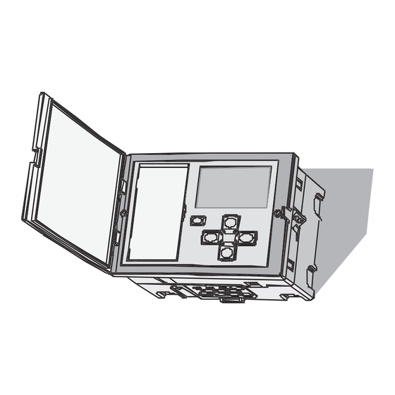
Page 11: Using The Operator's Panel
TAC 2413 Handbook Using the operator’s panel Using the operator’s panel 3.1 Introduction This chapter will show you how to use the buttons of the operator’s panel to read and set parameters, such as temperatures, for example. 3.2 What is shown in the display window? The display window provides you with information from the AHU in the form of numbers and symbols. -
Page 12: Parameter Numbers And Parameter Values
TAC 2413 Handbook Using the operator’s panel 3.2.1 Parameter numbers and parameter values The controller has a list of 100 parameters ranging from 0 to 99. Some of these parameters may be set, such as the room tempera- ture setpoint; others, however, can only be read, such as the out- door temperature. -
Page 13: Operating Modes
TAC 2413 Handbook Using the operator’s panel 3.2.2 Operating modes The different operating modes of the controller are shown in the display window by means of the symbols below. Operating mode The symbols of the operating modes of the controller... -
Page 14: Weekly Program
TAC 2413 Handbook Using the operator’s panel 3.2.3 Weekly program The weekly program is shown as a 24 hour time bar from 00:00 to 24:00 for each day of the week. The part of the bar that is filled shows when daytime operation applies. -
Page 15: Outputs Of The Controller
TAC 2413 Handbook Using the operator’s panel 3.2.4 Outputs of the controller The controller has a number of outputs for control, such as for the heating coil, and for controlling external units, such as the heating coil pump. When an output is active, its symbol is shown in the display window. -
Page 16: How Are The Buttons Used
TAC 2413 Handbook Using the operator’s panel 3.3 How are the buttons used? The controller has five buttons located below the display window. Enter Increase/decrease button parameter value Choose parameter The buttons on the operator’s panel buttons are used to choose a parameter. -
Page 17: Day-To-Day Usage
TAC 2413 Handbook Day-to-day usage Day-to-day usage 4.1 Introduction This chapter provides enough information for you to be able to read and set temperatures and other parameters during normal operation. All parameters and functions are explained in detail in Chapter 7, Functional description. -
Page 18: Setting Temperatures
TAC 2413 Handbook Day-to-day usage 4.3 Setting temperatures Procedure for setting a temperature: 1 Choose the parameter number (P No.) by using . You 10 11 12 13 14 15 16 17 can increase the number by pressing and decrease it by... -
Page 19: Weekly Program 1/1 Speed
TAC 2413 Handbook Day-to-day usage Parameter P No. Weekly program 1/2 speed P 12 4.4.2 Weekly program 1/1 speed For 1/1 speed to take effect, the weekly programs for both 1/2 speed and 1/1 speed operation have to be active. The 1/1 speed program is not set on delivery. - Page 20 TAC 2413 Handbook Day-to-day usage Procedure for setting a holiday period: 1 Choose parameter number P 15 by using . The 10 11 12 13 14 15 16 17 parameter number is increased by using and decreased by using 2 Choose a holiday period (1–6) by using...
-
Page 21: Reading And Resetting Alarms
TAC 2413 Handbook Day-to-day usage 4.5 Reading and resetting alarms When an alarm is tripped, the symbol will flash together with the symbol that the alarm is referring to. There are two types of alarms, A alarms and B alarms. Some alarms offer the opportun- ity of being tripped as A alarms or B alarms. -
Page 22: Setting The Clock
TAC 2413 Handbook Day-to-day usage Chosen mode Symbols in the display window Timed operation , and depending on the time schedule, Manual control (one speed operation) or with 4.7 Setting the clock To show the current time, choose parameter number P 00 (it is normally shown). -
Page 23: Installation
TAC 2413 Handbook Installation Installation 5.1 Mounting Controller Position the controller so that it is easy to read and to set values and so that the cover can be opened. The permissible ambient temperature and humidity range must not be exceeded. - Page 24 TAC 2413 Handbook Installation The controller can be mounted in three different ways: • Directly on a wall • On a norm rail EN 500 22 (TS 35 mm) • In a panel, with or without a backplate Procedure for mounting controller on a norm rail...
- Page 25 TAC 2413 Handbook Installation Procedure for mounting controller in a panel: 1 Make an opening in the panel as shown in the adjacent scale drawing. The maximum panel thickness is 5 mm. 2. Remove the backplate from the electronic part (see above).
-
Page 26: Connection
TAC 2413 Handbook Installation 5.2 Connection Connect the cables to the controller as shown in the wiring diagram. WARNING! All power cables should be installed by an authorised electrician. All equipment which is connected to the controller must comply with the following standards: •... - Page 27 K1: contactor TF01 K2: contactor FF01 N.B.! These drawings only show the units that may be connected to TAC 2413 using a heat exchanger as well as waterborne heating and cooling. TAC 2413 may use other combined functions. Designation Description...
-
Page 28: Terminal Blocks
The following applies when the TAC 24 V transformer is installed in direct connection to TAC 2413: • The cables to G, G0 and other terminal blocks on TAC 24 V actuators must not exceed 50 m in length, and shall have a minimum cross-sectional area of 0,8 mm . -
Page 29: Commissioning
TAC 2413 Handbook Installation 5.5 Commissioning The following should be done before switching on the power: 1. Check that sensors and actuators are connected correctly. 2. Set the DIP switch to configuration. Access to the DIP switch can be gained by pulling out the quick reference and removing the plastic sheet in front of it. - Page 30 TAC 2413 Handbook Installation Blank page. 5:8 (8), 0-004-7614-0 (GB) TAC AB, 1998-10-23...
-
Page 31: Troubleshooting
TAC 2413 Handbook Troubleshooting Troubleshooting TAC 2413 is normally a very reliable controller. If there should be any problem in spite of this, you may use the following tips for troubleshooting. If you need further help, please contact your ne- arest TAC service office. - Page 32 TAC 2413 Handbook Troubleshooting Problem Check that... The temperature in the • the AHU is in timed operation and ventilation system is too high no holiday program is active • an alarm has not stopped the AHU • high current protectors and power switches are on •...
-
Page 33: Functional Description
TAC 2413 Handbook Functional description Functional description 7.1 Introduction This chapter contains a description of all the functions of the controller. At the end of every section is a list of parameters. How parameters are read and set is described in Chapter 3, “Using the operator’s panel”. - Page 34 TAC 2413 Handbook Functional description When the controller is in the timed operating mode, and the holiday period starts, the clock symbol will be shown in the display window and the AHU stops. Air handling off When the controller is “Off”, the symbol on the left is shown in the display window and the AHU stops.
-
Page 35: Air Handling
TAC 2413 Handbook Functional description 7.3 Air handling 7.3.1 Fan operation The fans are controlled by the built-in time program with separate ti- mes for half and full speed, respectively, or via manual control by using the buttons. Full speed is disabled if the outdoor temperature is below the set limit in P90. - Page 36 TAC 2413 Handbook Functional description The heat recovery is controlled to 100 % when FF starts, and the posi- tion of the heating valve is determined by the outdoor temperature. It is completely closed at outdoor temperatures ≥ 10 °C, and opens on a linear basis without breakpoints with decreasing outdoor temperatures.
-
Page 37: Temperature Control
(0/1) Confirms the status P 23 Defrosting (0/1) Confirms the status 7.3.2 Temperature control TAC 2413 holds the temperature by sequence control of the heating coil, heat recovery and cooling coil, see the figure below. cooling recovery 100 % heating coil... -
Page 38: Outdoor Compensation
TAC 2413 Handbook Functional description P No. Parameter Factory set. Change Comment P 02 Supply air temp. setpoint Calculated P 04 Room/exhaust air temp. SP Calculated P 10 Heating setpoint 0 °C 50 °C 20 °C P 11 Cooling setpoint 0 °C... -
Page 39: Night Heating
TAC 2413 Handbook Functional description The winter compensation starts when the outdoor temperature is be- low “Start winter compensation”. The maximum compensation is achieved when the outdoor temperature is less than or equal to “Stop winter compensation”. P No. Parameter Min. -
Page 40: Night Cooling
The cooling demand which exists during the summer period in or- der to keep the right temperature will result in high operating costs. For this reason, TAC 2413 makes use of the relatively cold night air to cool the building down as well. The consequences are that less cool air, if any, needs to be supplied on the following day, and in all, the energy consumption has been decreased. -
Page 41: Co2 / Spc
TAC 2413 Handbook Functional description 7.3.6 CO / SPC This function is chosen by using parameter P 55; 0 = no function, 1 = SPC, and 2 = CO By connecting an external 2–10 V DC control voltage to the SPC in- put, the current setpoint can be shifted, see the figure below. -
Page 42: Mixed Air Damper
7.3.8 Heat recovery TAC 2413 is able to control all types of heat recovery by using the output Y2. The control strategy is chosen using DIP switches 3 and 4. The control signal is 0–10 V, where 0 V = 0 % recovery and 10 V =100 % recovery. - Page 43 P 38. There may be freezing in heat exchangers, which will have effect on the efficiency of the recovery AHU. For this reason, TAC 2413 has a built-in defrosting function which is activated by short-circuiting the exhaust air sensor with the differential pressu- re sensor.
-
Page 44: Heating Coil
TAC 2413 Handbook Functional description 7.3.9 Heating coil When the heating demand cannot be met, in spite of the heat recovery AHU controller being set to maximum recovery, the control sequence will include the heating coil. The control signal of the heating valve is 2–10 V, but by using DIP switch 7, 0–10 V can be chosen, where... - Page 45 TAC 2413 Handbook Functional description P No. Parameter Min. Max. Factory set. Change Comment P 06 Return temp., heating coil Measured value P 19 Output signal, heating valve P 26 Min. supply air temp. 0 °C 50 °C 14 °C...
-
Page 46: Electric Heating
10V=100% is equal to an open valve. The cooling coil will be engaged only when the temperature has in- creased so much that it has reached the cooling setpoint. TAC 2413 then switches from controlling by the heating setpoint to controlling by the cooling setpoint automatically. - Page 47 TAC 2413 Handbook Functional description The controller will return to heating control only when the supply air or room temperature has dropped to the “Heating setpoint”. The con- trol principle for both heating and cooling is to provide the highest possible comfort using the least possible energy by using advanced technology.
-
Page 48: Cooling Coil, Dx Cooling
TAC 2413 Handbook Functional description 7.3.12 Cooling coil, DX cooling, D DX cooling may be chosen by using DIP switch 6, and the choice is only valid if room control applies. One step is controlled using K5, and if there are several steps, they are controlled via Y3. The control signal is 2–10 V and by using DIP switch 7, 0–10 V can be chosen. -
Page 49: Cooling Recovery
22 °C 7.3.13 Cooling recovery TAC 2413 is able to make use of possible cooling content in the return air in order to decrease the energy consumption during cooling. When the return air temperature during cooling is lower than the out- door temperature, and the difference exceeds the “economy limit”, an... -
Page 50: Clock
0=ej aktiv, 1=mars till okt 7.4.2 Summer period Some functions depend on whether TAC 2413 is set for the summer period or winter period. The cooling control is only allowed to apply, and the pump for the heating coil is only allowed to stop, during the summer period. -
Page 51: Timer Programs
TAC 2413 Handbook Functional description 7.5 Timer programs TAC 2413 contains two weekly programs (1/1 and 1/2 speed) which control how the AHU starts and stops. Apart from the weekly pro- grams, there is a yearly program containing six holiday periods. 1/1 speed is disabled if the outdoor temperature is less than the limit set in P90. -
Page 52: Fire Alarm
TAC 2413 Handbook Functional description Fan alarm during waterborne heating When there is a fan alarm, the symbol flashes, and “TF” and “FF” are shown in the display window. The alarm is disabled during 60 seconds when TF is started. If it is tripped, that will happen with a 60 second delay after the fan guard closes the contact on input U4. -
Page 53: Frost Protection Alarm
TAC 2413 Handbook Functional description 7.6.3 Frost protection alarm When the frost protection alarm is tripped, the symbols will flash in the display window. When there is a risk of the heating coil freezing, the frost protection sensor in the return pipe will control the valve actuator so that it opens. -
Page 54: Freezing Alarm
TAC 2413 Handbook Functional description 7.6.5 Freezing alarm The symbols will flash when the freezing alarm is tripped. It is tripped if the defrosting has been activated by way of a closing contact from the pressure sensor and not been stopped within the “Max. -
Page 55: Deviation Alarm
TAC 2413 Handbook Functional description 7.6.7 Deviation alarm The symbols and “°C” will flash in the display window when the deviation alarm is tripped. If the supply air temperature deviates from the setpoint by more than an adjustable limit, which is factory set to ±3 °C, for 60 minutes, the alarm is tripped. - Page 56 TAC 2413 Handbook Functional description Blank page. 7:24 (24), 0-004-7614-0 (GB) TAC AB, 1998-10-23...
-
Page 57: Technical Data
TAC 2413 Handbook Technical data Technical data Thermistor inputs Thermistor type ............. 1800 Ω/25 °C Measurement range: Supply air temperature, B1 ..0 °C – +45 °C Outdoor temperature, B2 ..-30 °C – +45 °C Room temperature, B3 ....0 °C – +45 °C Return sensor, B4 ..... - Page 58 TAC 2413 Handbook Technical data Clock Accuracy ........±16 minutes/year at +25 °C Memory backup ......48 hours; no battery is required Power supply Operating voltage ......24 V AC ±20%, 50–60 Hz (variations included) Power consumptoin ............... 3 W Electromagnetic compatibility Emission ..............
-
Page 59: Appendix A: Commissioning Protocol
TAC 2413 Handbook Commissioning protocol/List of parameters Appendix A: Commissioning protocol/ List of parameters This protocol is used during commissioning of the TAC 2413 controller. Note the changed settings in the column labeled “Change”. DIP switch Default Change Supply air control... - Page 60 TAC 2413 Handbook Commissioning protocol/List of parameters P No. Parameter Min. Max. Step Default Change Comment P 00 Time. Indication and Off, Manual, Timed operation choice of operating mode 1/2 and 1/1 speed P 01 Supply air temperature 0,1 °C...
- Page 61 TAC 2413 Handbook Commissioning protocol/List of parameters P No. Parameter Min. Max. Step Default Change Comment P 31 Min. damper position 100 % 30 % P 32 Delay—start TF at 5 sec 300 sec 1 sec 5 sec ° P 33 Delay—start TF at...
- Page 62 TAC 2413 Handbook Commissioning protocol/List of parameters P No. Parameter Min. Max. Step Default Change Comment P 43 Min outd. temp. for night cool. 0 °C 50 °C 0,1 °C 12 °C P 44 Max. time to next normal 20 h...
- Page 63 TAC 2413 Handbook Commissioning protocol/List of parameters P No. Parameter Min. Max. Step Default Change Comment P 66 P band, holding controller 1 °C 400 °C 0,1 °C 200 °C P 67 I time, holding controller 1 min 20 min...
- Page 64 TAC 2413 Handbook Commissioning protocol/List of parameters Blank page. App:6 (6), 0-004-7614-0 (GB) TAC AB, 1998-10-23...
-
Page 65: Index
TAC 2413 Handbook Index Index enclosure 8:2 other inputs 8:1 alarm operating mode other outputs 8:1 pump alarm 7:21 priority 7:2 power supply 8:2 relay outputs 8:1 thermistor inputs 8:1 Cable lengths 5:6 parameter numbers 3:2 temperature control 7:5 Choosing the operating... - Page 66 TAC 2413 Handbook Index Blank page. Ind:2 (2), 0-004-7614-0 (GB) TAC AB, 1998-10-23...
- Page 67 Alternately, you may send e-mail to: TAC AB helpdesk@tac.se Helpdesk Jägershillgatan 18 SE-213 75 MALMÖ SWEDEN I have discovered the following errors and/or unclear descriptions in the TAC 2413 Handbook, part number 0-004-7614-0 (GB): On page: ................................................................................................ On page: ..............................................................
- Page 68 TAC 2413 Handbook Reply form TAC AB, 1998-10-23...
- Page 69 TAC 2413 Handbook Reply form TAC AB, 1998-10-23...
- Page 70 TAC 2413 Handbook Reply form TAC AB, Jägershillgatan 18, SE-213 75 MALMÖ, SWEDEN, +46 40 38 68 50 (switchboard) TAC AB, 1998-10-23...
Need help?
Do you have a question about the 2413 and is the answer not in the manual?
Questions and answers