Table of Contents
Advertisement
Quick Links
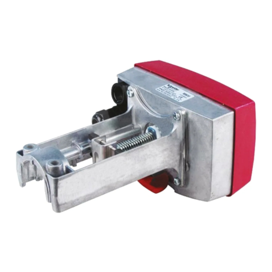
M800 is an electro-mechanical actuator for the control of
two-way and three-way plug valves in:
•
domestic hot water systems
•
heating systems
•
air handling systems
M800 is either controlled by an increase/decrease signal
or by a modulating 2–10 V control signal. Modulating
control makes for a faster positioning of the actuator.
The electronic circuitry of the actuator ensures that the
running time is the same, regardless of the stroke of the
valve in question.
It is easy to mount and connect the actuator. It can be
mounted directly onto TAC's control valves, without any
mounting kit.
The working range of the actuator is adjusted
automatically depending on the stroke of the valve. The
electronic circuitry of the actuator then takes care of the
adjustment of the valve end positions.
The actuator is supplied by 24 V AC. It can provide
16 V DC voltage supply for older TAC controllers.
TECHNICAL DATA, M800
Part numbers ....................... see the table on the next page
Supply voltage .................. 24 V AC +10%/ -40%, 50–60 Hz
Power consumption ...................................... average 15 VA
Transformer sizing ...................................................... 50 VA
Running time:
Modulating 10–25 mm (0.39 - 1 in.) ........................... 15 s
Modulating 25–32 mm (1 - 1.26 in.) ........................... 20 s
Modulating 10–52 mm (0.39 - 2.05 in.) ...................... 30 s
Increase/decrease ............................................ 300 s/60 s
Close off time with STS, at power failure:
Stroke 10–25 mm (0.39 - 1 in.) ......................... max. 20 s
Stroke 25–32 mm (1 - 1.26 in.) ......................... max. 25 s
Stroke 32–52 mm (1.26 - 2 in.) ......................... max. 35 s
Stroke ............................................. 10–52 mm (0.39 - 2 in.)
Factory set stroke ................................... 41 mm (1.61 in.)
Thrust .......................................................... 800 N (180 lbf.)
Duty cycle .......................................... max. 20%/60 minutes
Analog input:
Voltage .................................................................. 0–10 V
Impedance ..................................................... min 100 kΩ
Digital inputs VH–VC:
Voltage across open input .................................. 24 V AC
Current through closed input .................................... 5 mA
Pulse time ....................................................... min. 20 ms
Subject to modification.
TAC Forta M800
Actuator for valves
Output G1:
Voltage ..................................................... 16 V DC ±0.3 V
Load ......................................... 25 mA, short-circuit proof
Output Y:
Voltage ................................................... 2-10 V (0-100%)
Load ......................................................................... 2 mA
Ambient temperature:
Operation ............................ –10 – +50 °C (14°F - 122°F)
Storage ................................ –10 – +50 °C (14°F - 122°F)
Ambient humidity ............................................ max. 90% RH
Enclosure rating ........................................................... IP 54
Sound power level ........................................... max. 40 dBA
Standards:
Emission ............................................... EN 50081-1:1992
Immunity ............................................... EN 50082-1:1992
Heat ................................................................. IEC-68-2-2
Humidity .......................................................... IEC-68-2-3
Cold ................................................................. IEC-68-2-1
Vibration .......................................................... IEC-68-2-6
Material:
Housing ............................................................ aluminium
Cover ........................................................ ABS/PC plastic
Color ........................................................... aluminium/black
Weight ......................................................... 1.8 kg (3.96 lb.)
Dimensions (mm) .......... refer to the table on the next page
1 (8)
G-40-36
11 Jan 2005
0-003-2063-2 (EN)
Advertisement
Table of Contents

Related Manuals for TAC Forta M800


Summary of Contents for TAC Forta M800
- Page 1 The actuator is supplied by 24 V AC. It can provide 16 V DC voltage supply for older TAC controllers. TECHNICAL DATA, M800 Part numbers ....... see the table on the next page Output G1: Voltage .............
- Page 2 PART NUMBERS Designation Explanation Part number M800 modulating control signal or increase/decrease signal 880-0310-030 M800-S2 modulating control signal or increase/decrease signal and end point switches 880-0311-030 M800-STS modulating control signal or increase/decrease signal and self testing safety device 880-0312-040 M800-S2-STS modulating control signal or increase/decrease signal with end point switches and self testing safety device 880-0313-040...
- Page 3 MOUNTING The actuator may be mounted horizontally, vertically and in any position in between, but not upside down, see figure 3. N.B.! Do not use the actuator for the DN15 valves V298, V282, V294, V384, V386 and V394. To mount the actuator on a valve, slide the actuator onto the valve neck, thus making the square nut on the valve spindle fit into the groove on the cross...
- Page 4 CONNECTIONS Block Function Description N.B.! When installed with three is larger than 1.5 mm2 (AWG 16) and conductors, where the control signal the cables are only connected to one 24 V AC Supply reference is connected to G0, the motor actuator.
- Page 5 Forta Modulating control, 24 V AC supply to the controller (TAC 239W, TAC 6711, TAC Xenta, TAC 8000, TAC 230U, TAC 2000, TAC 9000, TAC 77xx) Normal installation (5 wires to the actuator) Short cable installation (4 wires to the actuator)
- Page 6 Forta Modulating control, 24 V AC supply to the controller (TAC 239W, TAC 6711, TAC Xenta, TAC 8000, TAC 230U, TAC 2000, TAC 9000, TAC 77xx) Normal installation (5 wires to the actuator) Short cable installation (4 wires to the actuator)
- Page 7 2 Control signal—MOD / INC manual operation handle lowered, TAC Forta can either be controlled by a the settings done, and then the variable direct voltage, a so called 6 Running time—60 s / 300 s handle raised again.
- Page 8 The actuator is maintenance-free. TAC Forta Handbook (GB) ..............0-004-7804 S2-Forta ....................880-0104-000 STS-Forta M310/M800 ................ 880-0107-010 NiCd batteries for the STS ..............1-001-9024-0 TAC AB, Jägershillgatan 18, SE-213 75 MALMÖ, SWEDEN, +46 40 38 68 50 (switchboard), tac.com 0-003-2063-2 (EN) 8 (8)
Need help?
Do you have a question about the Forta M800 and is the answer not in the manual?
Questions and answers